EP0916456A2 - Elektrohandwerkzeugmaschine - Google Patents
Elektrohandwerkzeugmaschine Download PDFInfo
- Publication number
- EP0916456A2 EP0916456A2 EP99103025A EP99103025A EP0916456A2 EP 0916456 A2 EP0916456 A2 EP 0916456A2 EP 99103025 A EP99103025 A EP 99103025A EP 99103025 A EP99103025 A EP 99103025A EP 0916456 A2 EP0916456 A2 EP 0916456A2
- Authority
- EP
- European Patent Office
- Prior art keywords
- housing
- tool
- machine according
- output shaft
- bearing
- Prior art date
- Legal status (The legal status is an assumption and is not a legal conclusion. Google has not performed a legal analysis and makes no representation as to the accuracy of the status listed.)
- Granted
Links
Images



Classifications
-
- B—PERFORMING OPERATIONS; TRANSPORTING
- B24—GRINDING; POLISHING
- B24B—MACHINES, DEVICES, OR PROCESSES FOR GRINDING OR POLISHING; DRESSING OR CONDITIONING OF ABRADING SURFACES; FEEDING OF GRINDING, POLISHING, OR LAPPING AGENTS
- B24B23/00—Portable grinding machines, e.g. hand-guided; Accessories therefor
- B24B23/04—Portable grinding machines, e.g. hand-guided; Accessories therefor with oscillating grinding tools; Accessories therefor
-
- B—PERFORMING OPERATIONS; TRANSPORTING
- B25—HAND TOOLS; PORTABLE POWER-DRIVEN TOOLS; MANIPULATORS
- B25F—COMBINATION OR MULTI-PURPOSE TOOLS NOT OTHERWISE PROVIDED FOR; DETAILS OR COMPONENTS OF PORTABLE POWER-DRIVEN TOOLS NOT PARTICULARLY RELATED TO THE OPERATIONS PERFORMED AND NOT OTHERWISE PROVIDED FOR
- B25F5/00—Details or components of portable power-driven tools not particularly related to the operations performed and not otherwise provided for
- B25F5/02—Construction of casings, bodies or handles
Definitions
- the invention relates to an electric hand machine tool according to the preamble of claim 1.
- DE-OS 42 35 278 is a generic hand tool known whose file-like insert tool by an eccentric output shaft via a Driver is driven back and forth.
- the output shaft is driven by an electric motor through an angular gear Movement set, the approximately 90 ° relative to the motor shaft angled output shaft no adjustment means for Setting the angular gear play, i.e. the play of the output shaft compared to the motor shaft or the axial play the output shaft opposite the housing.
- the top The end of the output shaft is in the upper area of the gearbox from an axial and radial force absorbing Rolling bearings and the lower shaft end in the lower area of the Gearbox housed by a needle bearing.
- the division level of the housing runs as before usual for hand-held power tools, vertical in the working position and even, with at least one bearing point of the output shaft is in the area of the division level, i.e. that the Camp seat is also shared.
- This allows the insert tool forces transmitted to the housing to a Deformation of the housing edges in the area of the division level to lead. This in turn can affect the bearing seats of the output shaft deform and thus interfere with the transmission function.
- the clamping means for the tool are in the clamping and releasing position from the outside using controls movable, but must also the movement of the driver and can follow the tool. That’s why Clamping device for coupling the insert tool with the driver designed relatively complex.
- the electric hand machine tool according to the invention with the characterizing features of claim 1 has the advantage that the output shaft with respect to the input shaft and opposite the housing can be optimally adjusted. In order to is an effective tolerance compensation created by the use roughly tolerated, inexpensive to manufacture parts for the housing and the gearbox.
- the positioning device is against unwanted adjustment with a Secure against rotation relative to the housing, whereby the anti-rotation lock in a particularly simple version an externally toothed clamping ring, the inside with a Double an opposite double on the lower outside the bearing bush from the one facing the collar or the ring wedge Reaches over here.
- the detachable arrangement of the anti-rotation device on one, in particular tool-facing side accessible from the outside enables adjustment of the axial play of the output shaft without dismantling the hand tool.
- the support is simple and inexpensive in that the output shaft via a spring-loaded, axially displaceable Ball against the housing supports and that a compression spring is arranged in the upper housing shell, the one on the housing side mandrel and the other one engages around a support disk-bearing pin and over the support disc supports against the ball, which in a front recess in the upper end of the output shaft sits and protrudes beyond the edge of the recess.
- the bearing point in the upper housing shell can be skewed compensate the output shaft in that a ring-like Plain bearings to support the upper end of the output shaft is arranged, the tread is conical.
- the plain bearing is particularly similar to the misalignment of the output shaft effective from the fact that the tread of the plain bearing in its upper area over a length of about 2 to 3 mm cylindrical and adjoins it downwards in an opening at an angle of about 5 ° conical area, about 7 mm long.
- the conical Opening facilitates when assembling the hand machine tool the insertion of the output shaft into the slide bearing.
- the operation can be done with simple Means, namely via a push button with which the Driver can be moved by hand.
- the tool is in the area of its clamping end in one Longitudinal guide with little play and friction and thus the drive and the housing of work-related lateral forces as well resulting relieving changes in friction, by the longitudinal guide the flat clamping area of the tool and when working against twisting backs up.
- a sealing cap covers the opening of the front area of the Housing through which the shank of the tool passes. It serves as a sliding guide and vibration damping for the tool.
- the tool is a cross to its direction of movement cutting edge, it is particularly hasty can be used as a chisel, spatula or the like.
- the longitudinal guide is securely locked in the housing shell through a comprehensive, box-like profile with one Open at the back and front to allow the tool to pass through Recording tunnel.
- the housing is particularly resistant to deformation in that it from two with a horizontal division level in the working position composite housing shells is formed, the output shaft in both housing shells in one Bearing is rotatably mounted.
- the stability of the case will increased by the shells and those formed by dividing edges Split level in the neck area - in working position considered - bent down and run the kink serves as a handle.
- the stiffening of the Housing increases by attacking the operator's hand and as a result of the operators while working, which makes the Housing shells virtually intertwined and firmly against each other be tense.
- the driver is designed as a connecting rod with a head that has a projection becomes its unwanted one Avoid turning inside the housing and a special one quiet, low-wear running of the hand tool achieved, with the head in the notch of the longitudinal guide is guided to dampen vibrations.
- the axially parallel limits Arrangement of the driving projection for the eccentric pin with a radial distance to the recess, the rotatability of the driver opposite the eccentric pin and thus reduces friction and wear between the eccentric pin, the driver and the tool. It is advantageous that the recess of the clamping end of the Tool is circular and essentially the same Diameter as the projection of the driver.
- the longitudinal guide is immovable as a separate body Arranged inside the case once the case shells are screwed together.
- the longitudinal guide is supported in the direction of movement of the inserted tool against a front wall from one of the housing shells and is thereby captive and free of play but also easy to replace, held because the longitudinal guide after easy Lift off the housing shells in the front area can be removed from the housing.
- the longitudinal guide is a separate body, she takes the cassette-like over the shaft of the tool bending forces transmitted to the housing and conducts this continues on the housing, so that this only is subjected to low bending and twisting forces and can be carried out in lightweight construction, with rolling elements both ends of the guide slot of the longitudinal guide Wear or, the friction between the longitudinal guide and reduce the tool, because only roll instead of is permitted by sliding friction.
- the tool can be a chisel, scraper, spatula or the like. made of metal, e.g. Tungsten carbide or HSS steel. It is versatile, e.g. to carve, to remove Paint, wallpaper, carpet adhesive, foam backing, needle felt, PVC, also for cleaning work, e.g. Removing dirt, Adhesive and glue, plaster, plaster, filler, putty, Paint and silicone residues as well as mortar and concrete residues Building boards. Finally, it can also be used to prepare substrates be carried out, e.g. Screed and Preparation of concrete, smoothing of caterpillars and noses, grouting of cracks, removal of tile adhesive.
- substrates e.g. Screed and Preparation of concrete, smoothing of caterpillars and noses, grouting of cracks, removal of tile adhesive.
- the tool has a flat, in particular rectangular, cross-section that in a Longitudinal guidance, especially in a flat slot, can be performed is and elastic, leaf spring-like, bending forces when scraping records. This prevents the tool from twisting around its Longitudinal axis secured and springs when operating the scraper between the workpiece and the operator.
- the invention is based on exemplary embodiments shown in the drawing in the description below explained.
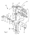
- FIG. 1 shows an exploded view and FIG. 2 a partial longitudinal section of an electric hand machine tool for scraping machining of workpieces, briefly as scrapers Designated 10.
- Whose cylindrical housing 11 is made of two Housing shells 12, 14 formed from plastic, the edges of which each form a dividing edge 15, which is a horizontal dividing plane define.
- the housing 11 has in its rear Area a thickening 30 and in its front area a neck 32 inclined with respect to the housing axis.
- the housing is between the neck 32 and the thickening 30 designed as a handle 28.
- the housing shells 12, 14 are connected to each other by screws 26.
- An electrical cable (not shown) can be attached to the housing 11 secured by a further screw 24 secured with a clamp become.
- a motor 16 is located inside the housing 11 arranged with a fan wheel 18, the drive shaft 19th stored in a ball bearing 20 and with a tapered Pinion 22 is rotatably connected.
- the pinion 22 meshes with one supported by an output shaft 50 in a rotationally fixed manner conical ring gear 48, the axis of rotation 36 at right angles to Drive shaft 19 extends.
- the bearing point of the output shaft 50 remote from the tool exists from a ring-shaped into a cylindrical bearing seat 38 the housing shell 12 insertable plain bearing 40, in particular made of sintered material, a compression spring 42, a support disc 44 and a ball 46 which is in a central Recess 43 in the upper end face of the output shaft 50 is stored.
- the compression spring 42 engages around the top, i.e. one end, one fixed to the housing Mandrel 41 and below, i.e. elsewhere, a one Support disc 44 bearing pin 44 'and is supported the support disc 44 opposite the ball 42, which in the Central recess 43 of the output shaft 50 is seated, wherein it projects beyond the edge of the recess 43.
- the plain bearing 40 has a tapered or crowned inner tread 47 for receiving the upper bearing end of the output shaft 50. and also by the axial support on the ball 46 the output shaft 50 can be inclined by a certain amount out of play with respect to the central axis of the plain bearing 40 are destroyed without the plain bearing 40 being destroyed becomes. This enables the use of roughly tolerated Individual parts for the scraper 10, its function in high quality is assured.
- the bearing near the tool of the output shaft 50 exists from a sleeve-like bearing bush 56, an annular disc 54 and a roller bearing or needle bearing 58.
- Eccentric pin 52 with an eccentric axis 53 passes through Bearing bush 56, with its free end from above into one Bore 72 of a connecting rod-like driver 68 engages is supported axially downward on a pushbutton 76. It can also other eccentric drives known per se be used.
- the distance between the eccentric axis 53 and the axis of rotation 36 determines the eccentricity, being double eccentricity determines the stroke of the eccentric pin or driver 69.
- the Anti-rotation lock designed as an adjusting washer or clamping ring 62 is for positive engagement around the bearing bush 56 educated.
- the push button 76 closes a dust-tight Opening 60 in the lower housing shell 14 and ends there flush with the housing contour.
- a transverse wall 13 is in the area of the opening 34 in the upper plastic shell 12 arranged and engages over the outer end face 82 'of Longitudinal guide 82 partially and thus secures it against unwanted emergence from the opening 34 or against To lose.
- the shaft 89 of the Tool 88 straight, moved back and forth.
- the driver 68 engages with a pin Projection 70 rotatable from above into a circular Recess 90 of the clamping end 77 of the shaft 89 of the Tool 88.
- Figures 2 and 4 show that for low-friction, better Bearing of the eccentric pin 52 of the driver 68 in its Bore 72 for the passage of the eccentric pin 52 a roller bearing 73, in particular needle bearings.
- the one with the recess 90 cooperating pin 70 is at a distance arranged axially parallel to the recess 72 or the roller bearing 73.
- Figures 1 to 4 show that the driver 68th guided along the eccentric pin 52 and axially displaceable is mounted and that the projection 70 of the driver 68 out of engagement with its axial displacement the recess 90 of the tool 88 can be brought, so that the drive can be separated from the tool 88. Is if this is the case, the tool 88 can then be easily moved by hand removed and replaced.
- the driver 68 is on the fingers of the operating hand sliding pushbutton 76 moved to the release position.
- the push button 76 is in the housing 11 in the opening 60 - like an engine piston in the cylinder - slidable in the Housing shell 14 mounted, the push button 76 in the same direction as the carrier 68 on which it is supported, movable is.
- a Compression spring 64 arranged at one end over an annular disc 66 supported on the driver 68 or the push button 76 and return it to its starting position.
- the compression spring 64 is supported against the driver 68.
- the Washer 66 prevents the reciprocating movement of the driver 68 transferred to the compression spring 64 becomes.
- the push button 76 means inside the housing shell 12 snap hooks 75, 79 is secured against falling out.
- To support against the rod-like driver 68 carries the push button 76 radial Ribs 8 and 9.
- the tool 88 is in a range between its one Cutting load-bearing working end 92 and its clamping end 77 guided in the longitudinal guide 82.
- the longitudinal guide 82 is like this formed, see also Fig. 9 that the flat shaft 89 of the tool 88 engages like a cassette and thereby the absorbs bending forces occurring when working, so that no local voltages can occur which lead to Destruction of the housing shells 12, 14 would result
- the longitudinal guide 82 can be inserted into the housing 12, 14 Cubes or cuboids with a continuous guide slot 67, see Figures 6 and 8, for the passage of the Shaft 89 of the tool 88 designed.
- the longitudinal guide 82 has one on its side facing the driver 68 Notch 83 on the in the recess 90 of the Clamping 77 of the tool 88 gripping head 65 of the Centered driver 68, which in the clamping end 77 of Tool 88 engaging and this engaging projection 70 wears.
- the longitudinal guide 82 does not have to be shaped like a cuboid, but can also have a different exterior depending on your needs Have design.
- Figures 1 to 7 show that the tool facing Bearing point of the output shaft 50 through the roller bearing 58 bearing bushing 56 is formed, which has a like a helical wedge acting on a Mating ring wedge 63 (Fig. 10) of the housing shell 14 after Releasing the anti-rotation device 62 is axially adjustable and the - after removing the key 76 and the driver 68 -, from outside e.g. for a wrench or the like for turning is accessible.
- the bearing bush 56 could instead of the ring wedge 57 Wear steep external threads that fit into a suitable housing Counter thread should be screwable.
- the anti-rotation device of the bearing bush 56 is externally toothed Clamping ring 62 designed with two on his Internally arranged teeth 61 in two opposite Grooves 59 on the lower outside of the bearing bush 56 takes hold.
- the clamping ring 62 holds with its external teeth on projections of the housing 11, in particular the housing shell 12, snapping securely by the teeth grip between cams 67 (FIG. 10) at the bottom of the opening 60. He thus secures the bearing bush 56 against twisting the housing 11.
- the compression spring 64 is supported on the clamping ring 62, with which it is this axially relative to the bearing bush 56 or relative to the Biased housing 11 and thus in particular on the cams holds on.
- the clamping ring 62 has an external toothing the housing shell 14 rotatably connected.
- the tool 88 or 188 exits the opening 34 of the front covered by a sealing cap 86 Area of the housing 11.
- a knife guard 94 can be placed, which secures the cutting edge against damage and the operators especially when transporting the Hand machine tool 10 against cutting edge injury protects.
- a driver 69 as a perforated disc trained - in contrast to that according to the figures 1 to 3 connecting rod-shaped driver 68.
- the driver 69 engages an eccentric pin 51 of the output shaft 50, which is significantly shorter as the eccentric pin 52 according to Figures 1 to 3. This a shorter dimension is necessary because the eccentric pin 51 even out of engagement with the recess 91 of the clamping end of the insert tool 188, thereby the insert tool 188 across the eccentric pin 51 - over the latter free end can be pushed past - can be removed.
- the slot-like recess 91 is arranged near the free end of the clamping end 77, wherein their longitudinal extent transverse to the direction of movement of the tool 188 runs and at least around the stroke h or around the double eccentricity of the eccentric pin 51 is longer than the diameter of the eccentric pin 51.
- the width of the elongated hole 91 is dimensioned so that the projection 71 essentially can intervene without play.
- FIG. 8 shows an insert tool 288 that is used for the scraper 10 according to Figures 1 to 4 is suitable.
- Insert tool 288 has a recess 93 in the clamping end 77 on that as extending longitudinally to the direction of movement Elongated hole is designed, the width of the outer diameter of the pin 70, which is circular in cross section is. Its longitudinal extent is around the stroke h or around the double eccentricity of the eccentric pin 52 larger than that Outer diameter of the eccentric pin 52 Motor only then back and forth the tool 288 moved or driven when it is from a frontal Opposing force is applied so that the projection 70th Drivingly supported on the front edge 193 of the recess 90 can.
- a comparison of the clamping ends 77 of the insert tools 88, 188, 288 according to Figures 1 to 8 shows that the recess 90 of the insert tool 88 further from the free end of the clamping end 77 removed as the recess 91 of the insert tool 188 and as the recess 93 of the insert tool 288 according to FIGS. 5 and 7.
- FIG. 9 shows the longitudinal guide 82 according to the enlargement Figure 1.
- the longitudinal guide 82 carries designed as needles Rolling elements 78 and 84, which are in front of and behind the rectangular, flat guide slot 67 are arranged and on which can support the tool 88, 188, 288 on a rolling basis.
- the rolling elements 78 and 84 are in corresponding slots 85 of the Longitudinal guide 82 stored. This arrangement of the rolling elements 78, 84 becomes sliding friction in the longitudinal guide 82 significantly reduced, their resilience increases as well as heat development and wear on the scraper 10 is reduced and Bending forces of the insert tool 88, 188 and 288 from the housing 11 kept away.
- the cooperation between the longitudinal guide 82 and the Connecting rod-like carriers 68 are shown in FIGS. 1, 2 and 4.
- the driver 68 has the projection 70 carrying Head part 65, in the notch serving as a guide slot 83 of the longitudinal guide 82 snaps into place. Thereby it is ensured that the head 65 and thus the driver 68 also secured against rotation within the housing 11 is guided when the scraper 10 is not with a tool 88, 288 and if the motor is in this state 16 is started.
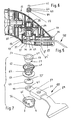
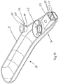
- the upper and lower housing shell 12, 14 shown pulled apart parallel to the axis, wherein the inclined course of the dividing edge 15, which is bent at the front is clear with both housing shells.
- the upper case shell shows particularly clearly the mandrel 41 and the associated concentric bore 45 for receiving the not shown here, but shown in Figures 1 to 3, 5, 6 Compression spring 42, which in turn pin 44 'with the washer 44 contributes to the axial support on the ball 46 or on the Output shaft 50.
- the front one Transverse wall 13 near the opening 34 for the passage of the here not shown tool 88 particularly clearly visible.
- the lower housing shell 14 clearly shows the counter ring wedge surface 63, on which the ring wedge 57 on the collar 55 of the Bearing bush 56 supports, so that when the bearing bushing rotates 56 counterclockwise this moves axially.
- the output shaft 50 according to Figures 1, 2 and 5 axially is supported on the bearing bush, it turns when the bearing bush is turned 56 axially entrained, so that the setting the axial play of the output shaft 50 relative to the upper housing shell 12 or opposite the ball 46, the Washer 44 and the mandrel 41 is possible.
- the adjusting means in the form of the bearing bush 56 could also instead of in the lower housing shell 14 in the upper housing shell 12 may be arranged, then instead of the needle bearing 73 the plain bearing 40 is seated in the bearing bush 56 could.
Landscapes
- Engineering & Computer Science (AREA)
- Mechanical Engineering (AREA)
- Drilling And Boring (AREA)
- Jigs For Machine Tools (AREA)
- Portable Nailing Machines And Staplers (AREA)
- Grinding-Machine Dressing And Accessory Apparatuses (AREA)
Abstract
Description
Claims (21)
- Handwerkzeugmaschine mit einem aus längsgeteilten Schalen (12, 14) bestehenden Gehäuse (11), das ein Winkelgetriebe mit einer beidenends gelagerten Abtriebswelle (50) aufnimmt, dadurch gekennzeichnet, daß das Gehäuse (11) aus zwei mit in Arbeitsposition waagerecht verlaufender Teilungsebene zusammengesetzten Gehäuseschalen (12, 14) gebildet wird, wobei die Abtriebswelle (50) in beiden Gehäuseschalen (12, 14) in je einem Lager (40, drehbar gelagert ist.
- Maschine nach Anspruch 1, dadurch gekennzeichnet, daß das Gehäuse (11) mit den beiden Gehäuseschalen (12, 14) und die durch Teilungskanten (15) gebildete Teilungsebene, insbesondere im Bereich des Halses (32), in Arbeitsposition s-förmig nach unten abgeknickt verlaufen.
- Maschine nach Anspruch 2, dadurch gekennzeichnet, daß eine, vorzugsweise die werkzeugzugewandte, Lagerstelle (58) der Abtriebswelle (50) mit mindestens einem die Abtriebswelle (50) gegenüber dem Gehäuse (11) axial verstellbaren Stellmittel (56) in Wirkverbindung steht.
- Maschine nach Anspruch 3, dadurch gekennzeichnet, daß das Stellmittel (56) als, insbesondere mit einem Steilgewinde (57, 63), im Gehäuse (11) axial verstellbare Lagerbuchse (56) ausgestaltet ist.
- Maschine nach Anspruch 2, dadurch gekennzeichnet, daß als Steilgewinde die Lagerbuchse (56) an der Unterseite eines oberen, radialen Bundes (55) mindestens einen Ringkeil (57) trägt, dem ein gehäuseseitiger Gegen-Ringkeil (63) als Abstützfläche zugeordnet ist.
- Maschine nach einem der Ansprüche 1 bis 5, dadurch gekennzeichnet, daß die Lagerbuchse (56) mit einer Verdrehsicherung (62) gegenüber dem Gehäuse (11) lagesicherbar ist.
- Maschine nach Anspruch 6, dadurch gekennzeichnet, daß die Verdrehsicherung als außenverzahnter Klemmring (62) ausgestaltet ist, der verdrehsicher, insbesondere innen mit mindestens einem Innenzahn (61) in mindestens eine Nut (59) auf der unteren Außenseite der Lagerbuchse (56) eingreift und die Lagerbuchse (56), insbesondere von der dem Ringkeil (57) zugewandten Seite her, übergreift.
- Maschine nach Anspruch 7, dadurch gekennzeichnet, daß sich der Klemmring (62) mit seiner Außenverzahnung an Vorsprüngen des Gehäuses (11), insbesondere an Nocken (67) am Boden der Öffnung (60) der Gehäuseschale (12), einrastend festhält.
- Maschine nach Anspruch 8, dadurch gekennzeichnet, daß sich eine Druckfeder (64) am Klemmring (62) abstützt und diesen gegenüber der Lagerbuchse (56) bzw. dem Gehäuse (11) festhält.
- Maschine nach einem der Ansprüche 6 bis 9, dadurch gekennzeichnet, daß die Verdrehsicherung (62) auf einer, insbesondere werkzeugzugewandten, von außen zugänglichen Seite des Gehäuses (11) aus seiner Festhalteposition lösbar angeordnet ist.
- Maschine nach Anspruch 8, 9 oder 10, dadurch gekennzeichnet, daß eine Drucktaste (76) zum Lösen des Einsatzwerkzeugs (88) sich an der Druckfeder (64) abstützt, so daß diese zugleich als Rückstellfeder für den Mitnehmer (68) und die Drucktaste (76) dient, wobei die Drucktaste (76) gegen Herausfallen aus der Maschine (10) gesichert ist.
- Maschine nach einem der Ansprüche 1 bis 11, dadurch gekennzeichnet, daß die Abtriebswelle (50) sich an der werkzeugfernen Seite axial federnd gegenüber dem Gehäuse (11) abstützt.
- Maschine nach Anspruch 11, dadurch gekennzeichnet, daß sich die Abtriebswelle (50) über eine federnd gelagerte, axialverschiebliche Kugel (46) gegenüber dem Gehäuse (11) abstützt.
- Maschine nach Anspruch 13, dadurch gekennzeichnet, daß in der oberen Gehäuseschale (12) eine Druckfeder (42) angeordnet ist, die einenends einen gehäuseseitigen Dorn (41) und andernends einen eine Stützscheibe (44) tragenden Zapfen (44') umgreift und sich über die Stützscheibe (44) gegenüber der Kugel (46) abstützt, die in einer stirnseitigen Ausnehmung (43) im oberen, werkzeugfernen Ende der Abtriebswelle (50) sitzt und über den Rand der Ausnehmung (43) hinausragt.
- Maschine nach Anspruch 14, dadurch gekennzeichnet, daß in der oberen Gehäuseschale (12) ein ringartiges Gleitlager (40) zur Lagerung des oberen Endes der Abtriebswelle (50) angeordnet ist, dessen Lauffläche (47) zumindest bereichsweise, konisch ausgestaltet ist, so daß Schieflagen der Abtriebswelle (50) gegenüber der Mittelachse des Gleitlagers (40) ausgeglichen werden.
- Maschine nach Anspruch 14, dadurch gekennzeichnet, daß die Lauffläche (47) des Gleitlagers (40) in ihrem oberen Bereich (47''), vorzugsweise über eine Länge von etwa 2 bis 3 mm, zylindrisch verläuft und sich nach unten daran anschließend in einen sich unter einem Winkel von etwa 5° öffnenden konischen, vorzugsweise etwa 7 mm langen Bereich (47') übergeht.
- Maschine nach einem der vorhergehenden Ansprüche, dadurch gekennzeichnet, daß der Mitnehmer (68, 69) durch Verschieben mittels einer Drucktaste (76, 176) außer Eingriff zum Einsatzwerkzeug (88, 188, 288) bringbar ist, wodurch das Einsatzwerkzeug (88, 188, 288) vom Antrieb getrennt und dadurch leicht entnehmbar ist.
- Maschine nach einem der vorhergehenden Ansprüche, dadurch gekennzeichnet, daß das Einsatzwerkzeug (88, 188, 288) in einer Längsführung (82) im Gehäuse (11) axialverschieblich führbar ist, wobei dessen flaches Einspannende (77) von Führungselementen (82) spielarm umgriffen wird.
- Maschine nach einem der vorhergehenden Ansprüche, dadurch gekennzeichnet, daß das Einsatzwerkzeug (88, 188, 288) aus einer durch eine Dichtkappe (86) abgedeckten Öffnung (34) des vorderen Bereichs des Gehäuses (11) herausragt, wobei sich die Dichtkappe (86), insbesondere dichtend, am Einsatzwerkzeug (88, 188, 288) abstützt.
- Maschine nach einem der vorhergehenden Ansprüche, dadurch gekennzeichnet, daß das Einsatzwerkzeug (88, 188, 288) eine quer zu seiner Bewegungsrichtung verlaufende Schneide trägt und als Meißel, Spachtel oder dergl. dient.
- Maschine nach einem der vorhergehenden Ansprüche, dadurch gekennzeichnet, daß eine der Gehäuseschalen (12, 14) ein eine Längsführung (82) umgreifendes, kastenartiges Profil mit einem hinten und vorn zum Durchtritt des Einsatzwerkzeugs (88, 188, 288) offenen Aufnahmetunnel (33) enthält.
Applications Claiming Priority (3)
| Application Number | Priority Date | Filing Date | Title |
|---|---|---|---|
| DE19547332A DE19547332A1 (de) | 1995-12-19 | 1995-12-19 | Elektrohandwerkzeugmaschine |
| DE19547332 | 1995-12-19 | ||
| EP96934436A EP0868256B1 (de) | 1995-12-19 | 1996-10-26 | Elektrohandwerkzeugmaschine |
Related Parent Applications (1)
| Application Number | Title | Priority Date | Filing Date |
|---|---|---|---|
| EP96934436A Division EP0868256B1 (de) | 1995-12-19 | 1996-10-26 | Elektrohandwerkzeugmaschine |
Publications (3)
| Publication Number | Publication Date |
|---|---|
| EP0916456A2 true EP0916456A2 (de) | 1999-05-19 |
| EP0916456A3 EP0916456A3 (de) | 2002-09-25 |
| EP0916456B1 EP0916456B1 (de) | 2005-06-08 |
Family
ID=7780506
Family Applications (2)
| Application Number | Title | Priority Date | Filing Date |
|---|---|---|---|
| EP99103025A Expired - Lifetime EP0916456B1 (de) | 1995-12-19 | 1996-10-26 | Elektrohandwerkzeugmaschine |
| EP96934436A Expired - Lifetime EP0868256B1 (de) | 1995-12-19 | 1996-10-26 | Elektrohandwerkzeugmaschine |
Family Applications After (1)
| Application Number | Title | Priority Date | Filing Date |
|---|---|---|---|
| EP96934436A Expired - Lifetime EP0868256B1 (de) | 1995-12-19 | 1996-10-26 | Elektrohandwerkzeugmaschine |
Country Status (5)
| Country | Link |
|---|---|
| EP (2) | EP0916456B1 (de) |
| JP (1) | JP2000501029A (de) |
| CN (1) | CN1112982C (de) |
| DE (3) | DE19547332A1 (de) |
| WO (1) | WO1997022437A1 (de) |
Cited By (2)
| Publication number | Priority date | Publication date | Assignee | Title |
|---|---|---|---|---|
| GB2450582A (en) * | 2007-06-25 | 2008-12-31 | Chervon Ltd | An Electric Sanding Machine |
| US11311952B2 (en) | 2018-01-31 | 2022-04-26 | Milwaukee Electric Tool Corporation | Reciprocating saw |
Families Citing this family (28)
| Publication number | Priority date | Publication date | Assignee | Title |
|---|---|---|---|---|
| DE29717071U1 (de) * | 1997-09-24 | 1999-02-04 | Robert Bosch Gmbh, 70469 Stuttgart | Handwerkzeugmaschine |
| DE19844806B4 (de) * | 1998-09-30 | 2010-10-14 | Robert Bosch Gmbh | Handwerkzeugmaschine, insbesondere Schnursäge |
| DE19938176A1 (de) * | 1999-08-16 | 2001-03-08 | Bosch Gmbh Robert | Handwerkzeugmaschine |
| DE19938161A1 (de) * | 1999-08-16 | 2001-03-01 | Bosch Gmbh Robert | Handwerkzeugmaschine |
| DE19938162A1 (de) * | 1999-08-16 | 2001-03-01 | Bosch Gmbh Robert | Handwerkzeugmaschinensystem |
| DE19938175B4 (de) * | 1999-08-16 | 2005-08-11 | Robert Bosch Gmbh | Handwerkzeugmaschine mit einem Führungslager für ein Einsatzwerkzeug |
| DE19939171A1 (de) * | 1999-08-20 | 2001-03-08 | Bosch Gmbh Robert | Handwerkzeugmaschine |
| DE20019375U1 (de) * | 2000-11-15 | 2001-03-01 | Scintilla Ag, Solothurn | Werkzeughalter |
| DE10058894A1 (de) * | 2000-11-23 | 2002-06-06 | C & E Fein Gmbh & Co Kg | Werkzeug mit einem Halter zur Befestigung an einer Antriebswelle |
| US7980325B2 (en) * | 2004-01-16 | 2011-07-19 | Credo Technology Corporation | Rotating shaft locking mechanism |
| US20090272556A1 (en) * | 2008-05-05 | 2009-11-05 | Ingersoll-Rand Company | Angle head and bevel gear for tool |
| JP2010155291A (ja) * | 2008-12-26 | 2010-07-15 | Makita Corp | 電動工具 |
| RU2013119819A (ru) * | 2010-10-04 | 2014-11-20 | Роберт Бош Гмбх | Осциллирующая ручная машина |
| DE102010041938A1 (de) * | 2010-10-04 | 2012-04-05 | Robert Bosch Gmbh | Materialverteilungseinheit |
| DE102010064363B4 (de) * | 2010-12-30 | 2021-12-16 | Robert Bosch Gmbh | Handwerkzeugmaschinenspannvorrichtung mit Verdrehsicherung |
| WO2014036003A1 (en) * | 2012-08-27 | 2014-03-06 | Ingersoll-Rand Company | Power tool housing construction |
| DE102013223819A1 (de) * | 2013-11-21 | 2015-05-21 | Robert Bosch Gmbh | Handwerkzeugmaschinengehäusevorrichtung |
| CN103894672B (zh) * | 2014-03-28 | 2017-01-11 | 潘杭 | 一种板材竖直矩形槽开槽机 |
| CN106424933B (zh) * | 2015-08-06 | 2018-06-19 | 南京德朔实业有限公司 | 往复锯 |
| CN105855917B (zh) * | 2016-06-06 | 2018-01-05 | 石狮市川朗机械设计有限公司 | 一种带加工头且能往复运动的加工机构 |
| CN106424932B (zh) * | 2016-11-17 | 2018-06-29 | 湖州峰霞五金贸易有限公司 | 一种受力平衡手锯 |
| CN106346363B (zh) * | 2016-11-18 | 2018-05-01 | 常州市武进大成工贸有限公司 | 雕磨机 |
| CN108000360B (zh) * | 2017-12-29 | 2024-03-15 | 宁波浙达技术服务有限公司 | 一种气动式打磨机 |
| CN108406478A (zh) * | 2018-02-08 | 2018-08-17 | 浙江意达电器有限公司 | 高密封性高稳定性角向磨光机及其磨光方法 |
| US11691261B2 (en) | 2020-06-02 | 2023-07-04 | Snap-On Incorporated | Housing clamp for a power tool |
| CN111791194B (zh) * | 2020-06-30 | 2025-09-09 | 浙江动一新能源动力科技股份有限公司 | 一种电动工具壳体及电动工具 |
| CN112353347B (zh) * | 2020-11-03 | 2023-01-03 | 青岛海泰新光科技股份有限公司 | 一种摄像手柄的楔形锁紧密封结构 |
| JP7634437B2 (ja) * | 2021-07-21 | 2025-02-21 | 株式会社マキタ | 往復動切断工具 |
Family Cites Families (9)
| Publication number | Priority date | Publication date | Assignee | Title |
|---|---|---|---|---|
| US2705980A (en) * | 1953-09-08 | 1955-04-12 | Walter A Papworth | Portable power driven reciprocating and oscillating cutting tool |
| US3203095A (en) * | 1963-07-29 | 1965-08-31 | Gen Electric | Power-operated knife |
| US4311063A (en) * | 1980-06-02 | 1982-01-19 | The Singer Company | Bearing and bearing mount and tools incorporating same |
| DE3448276C3 (de) * | 1984-08-01 | 1997-06-05 | Foell Remswerk | Stichsäge mit einer Klemmvorrichtung |
| JPH0351540Y2 (de) * | 1985-08-02 | 1991-11-06 | ||
| EP0548717A1 (de) * | 1991-12-21 | 1993-06-30 | Robert Bosch Gmbh | Handwerkzeugmaschine mit Winkelgetriebe |
| DE4235278A1 (de) * | 1992-10-20 | 1994-04-21 | Bosch Gmbh Robert | Handwerkzeugmaschine, insbesondere Motorfeile |
| WO1994014574A1 (en) * | 1992-12-21 | 1994-07-07 | Matricbrook Pty. Ltd. | Power driven ratchet wrench |
| DE4342986C2 (de) * | 1993-12-16 | 1998-08-13 | Metabowerke Kg | Motorbetriebenes Handwerkzeug mit Riemenantrieb |
-
1995
- 1995-12-19 DE DE19547332A patent/DE19547332A1/de not_active Ceased
-
1996
- 1996-10-26 DE DE59609803T patent/DE59609803D1/de not_active Expired - Lifetime
- 1996-10-26 EP EP99103025A patent/EP0916456B1/de not_active Expired - Lifetime
- 1996-10-26 CN CN96199108A patent/CN1112982C/zh not_active Expired - Lifetime
- 1996-10-26 JP JP9513779A patent/JP2000501029A/ja not_active Abandoned
- 1996-10-26 WO PCT/DE1996/002044 patent/WO1997022437A1/de not_active Ceased
- 1996-10-26 DE DE59611234T patent/DE59611234D1/de not_active Expired - Fee Related
- 1996-10-26 EP EP96934436A patent/EP0868256B1/de not_active Expired - Lifetime
Cited By (3)
| Publication number | Priority date | Publication date | Assignee | Title |
|---|---|---|---|---|
| GB2450582A (en) * | 2007-06-25 | 2008-12-31 | Chervon Ltd | An Electric Sanding Machine |
| GB2450582B (en) * | 2007-06-25 | 2012-04-04 | Chervon Ltd | An electric sanding machine |
| US11311952B2 (en) | 2018-01-31 | 2022-04-26 | Milwaukee Electric Tool Corporation | Reciprocating saw |
Also Published As
| Publication number | Publication date |
|---|---|
| DE59611234D1 (de) | 2005-07-14 |
| CN1112982C (zh) | 2003-07-02 |
| DE19547332A1 (de) | 1997-06-26 |
| EP0868256A1 (de) | 1998-10-07 |
| JP2000501029A (ja) | 2000-02-02 |
| WO1997022437A1 (de) | 1997-06-26 |
| EP0916456B1 (de) | 2005-06-08 |
| EP0916456A3 (de) | 2002-09-25 |
| EP0868256B1 (de) | 2002-10-16 |
| CN1205664A (zh) | 1999-01-20 |
| DE59609803D1 (de) | 2002-11-21 |
Similar Documents
| Publication | Publication Date | Title |
|---|---|---|
| EP0868256B1 (de) | Elektrohandwerkzeugmaschine | |
| EP0868264B1 (de) | Elektrohandwerkzeugmaschine | |
| EP0152564B1 (de) | Werkzeugbefestigung | |
| AT391825B (de) | Bohrfutter fuer handgeraete | |
| DE2825022C2 (de) | ||
| EP0591876A1 (de) | Exzentertellerschleifer mit Schleiftellerbremse | |
| EP0142611B1 (de) | Bohrwerkzeug zur Herstellung von Hinterschneidungen in vorgefertigten Bohrungen | |
| WO2009109247A1 (de) | Zusatzhandgriff sowie handwerkzeugmaschine | |
| EP3269504A1 (de) | Absaughaube für werkzeugmaschine | |
| DE102010031329A1 (de) | Werkzeughalterung für eine Werkzeugmaschine | |
| DE1477175A1 (de) | Automatisch verstellbare Bohrspindelhuelse | |
| EP0360161A2 (de) | Gerät zur Zahnbehandlung | |
| DE2226792A1 (de) | Motorgetriebene Handbohrmaschine | |
| DE69610820T2 (de) | Topfschleifscheibe und schleifscheibenhalter | |
| EP0711636B1 (de) | Hand-Oszillationsmaschine | |
| DE3431630A1 (de) | Elektrowerkzeug | |
| EP0842012B1 (de) | Schwingschleifer | |
| CH659202A5 (de) | Stellglied zum umschalten von elektrowerkzeugen vom betriebszustand ''bohren'' auf den betriebszustand ''hammerbohren oder schlagbohren'' und umgekehrt. | |
| EP0842011B1 (de) | Schwingschleifer | |
| DE102010012021B3 (de) | Hand-Werkzeugmaschine mit einem Exzentergetriebe und einer Sperre | |
| DE102018206135B4 (de) | Honwerkzeug mit auswechselbaren Schneidmitteln | |
| DE19531270A1 (de) | Hand-Oszillationsmaschine | |
| DE1502979B2 (de) | Feilgeraet | |
| DE1502979C (de) | Feilgerät | |
| CH406030A (de) | Von Hand geführte Werkzeugmaschine zur Steinbearbeitung |
Legal Events
| Date | Code | Title | Description |
|---|---|---|---|
| PUAI | Public reference made under article 153(3) epc to a published international application that has entered the european phase |
Free format text: ORIGINAL CODE: 0009012 |
|
| AC | Divisional application: reference to earlier application |
Ref document number: 868256 Country of ref document: EP |
|
| AK | Designated contracting states |
Kind code of ref document: A2 Designated state(s): DE GB IT NL |
|
| AX | Request for extension of the european patent |
Free format text: AL PAYMENT 19990316;LT PAYMENT 19990316;LV PAYMENT 19990316;RO PAYMENT 19990316;SI PAYMENT 19990316 |
|
| PUAL | Search report despatched |
Free format text: ORIGINAL CODE: 0009013 |
|
| AK | Designated contracting states |
Kind code of ref document: A3 Designated state(s): DE GB IT NL |
|
| AX | Request for extension of the european patent |
Free format text: AL PAYMENT 19990316;LT PAYMENT 19990316;LV PAYMENT 19990316;RO PAYMENT 19990316;SI PAYMENT 19990316 |
|
| 17P | Request for examination filed |
Effective date: 20030325 |
|
| GRAP | Despatch of communication of intention to grant a patent |
Free format text: ORIGINAL CODE: EPIDOSNIGR1 |
|
| DAX | Request for extension of the european patent (deleted) | ||
| GRAA | (expected) grant |
Free format text: ORIGINAL CODE: 0009210 |
|
| GRAS | Grant fee paid |
Free format text: ORIGINAL CODE: EPIDOSNIGR3 |
|
| AC | Divisional application: reference to earlier application |
Ref document number: 0868256 Country of ref document: EP Kind code of ref document: P |
|
| AK | Designated contracting states |
Kind code of ref document: B1 Designated state(s): DE GB IT NL |
|
| PG25 | Lapsed in a contracting state [announced via postgrant information from national office to epo] |
Ref country code: NL Free format text: LAPSE BECAUSE OF FAILURE TO SUBMIT A TRANSLATION OF THE DESCRIPTION OR TO PAY THE FEE WITHIN THE PRESCRIBED TIME-LIMIT Effective date: 20050608 Ref country code: IT Free format text: LAPSE BECAUSE OF FAILURE TO SUBMIT A TRANSLATION OF THE DESCRIPTION OR TO PAY THE FEE WITHIN THE PRE;WARNING: LAPSES OF ITALIAN PATENTS WITH EFFECTIVE DATE BEFORE 2007 MAY HAVE OCCURRED AT ANY TIME BEFORE 2007. THE CORRECT EFFECTIVE DATE MAY BE DIFFERENT FROM THE ONE RECORDED.SCRIBED TIME-LIMIT Effective date: 20050608 |
|
| REG | Reference to a national code |
Ref country code: GB Ref legal event code: FG4D Free format text: NOT ENGLISH |
|
| REF | Corresponds to: |
Ref document number: 59611234 Country of ref document: DE Date of ref document: 20050714 Kind code of ref document: P |
|
| PG25 | Lapsed in a contracting state [announced via postgrant information from national office to epo] |
Ref country code: GB Free format text: LAPSE BECAUSE OF NON-PAYMENT OF DUE FEES Effective date: 20051026 |
|
| NLV1 | Nl: lapsed or annulled due to failure to fulfill the requirements of art. 29p and 29m of the patents act | ||
| GBT | Gb: translation of ep patent filed (gb section 77(6)(a)/1977) | ||
| PLBE | No opposition filed within time limit |
Free format text: ORIGINAL CODE: 0009261 |
|
| STAA | Information on the status of an ep patent application or granted ep patent |
Free format text: STATUS: NO OPPOSITION FILED WITHIN TIME LIMIT |
|
| PG25 | Lapsed in a contracting state [announced via postgrant information from national office to epo] |
Ref country code: DE Free format text: LAPSE BECAUSE OF NON-PAYMENT OF DUE FEES Effective date: 20060503 |
|
| 26N | No opposition filed |
Effective date: 20060309 |
|
| GBPC | Gb: european patent ceased through non-payment of renewal fee |
Effective date: 20051026 |