EP0916533A2 - Sun visor for motor vehicles - Google Patents
Sun visor for motor vehicles Download PDFInfo
- Publication number
- EP0916533A2 EP0916533A2 EP98116901A EP98116901A EP0916533A2 EP 0916533 A2 EP0916533 A2 EP 0916533A2 EP 98116901 A EP98116901 A EP 98116901A EP 98116901 A EP98116901 A EP 98116901A EP 0916533 A2 EP0916533 A2 EP 0916533A2
- Authority
- EP
- European Patent Office
- Prior art keywords
- sun visor
- spring
- guide rail
- slide
- bridges
- Prior art date
- Legal status (The legal status is an assumption and is not a legal conclusion. Google has not performed a legal analysis and makes no representation as to the accuracy of the status listed.)
- Granted
Links
- 238000006073 displacement reaction Methods 0.000 claims description 4
- 230000006835 compression Effects 0.000 claims description 3
- 238000007906 compression Methods 0.000 claims description 3
- 239000002184 metal Substances 0.000 description 3
- 238000002347 injection Methods 0.000 description 2
- 239000007924 injection Substances 0.000 description 2
- 239000000463 material Substances 0.000 description 2
- 229910000639 Spring steel Inorganic materials 0.000 description 1
- 238000004519 manufacturing process Methods 0.000 description 1
- 230000003449 preventive effect Effects 0.000 description 1
Images

Classifications
-
- B—PERFORMING OPERATIONS; TRANSPORTING
- B60—VEHICLES IN GENERAL
- B60J—WINDOWS, WINDSCREENS, NON-FIXED ROOFS, DOORS, OR SIMILAR DEVICES FOR VEHICLES; REMOVABLE EXTERNAL PROTECTIVE COVERINGS SPECIALLY ADAPTED FOR VEHICLES
- B60J3/00—Antiglare equipment associated with windows or windscreens; Sun visors for vehicles
- B60J3/02—Antiglare equipment associated with windows or windscreens; Sun visors for vehicles adjustable in position
- B60J3/0204—Sun visors
- B60J3/0213—Sun visors characterised by the mounting means
- B60J3/0234—Mounted slidably
Definitions
- the invention relates to a sun visor for motor vehicles, in particular Commercial vehicles, primarily for arrangement in the long side area the driver's cab is determined and has a sun visor body, which has two pedestals, can be pivoted about an approximately horizontal axis is and over the bearing blocks along a parallel to the pivot axis Guide rail that is open in cross-section to the visible side C-shaped profile, is guided.
- the invention is based on the object, a sun visor to improve the quality mentioned at the beginning and in particular preventive measures to ensure that the sun visor body despite inevitable Manufacturing tolerances and temperature loads smoothly along the Guide rail is slidable without an automatic slidability is possible.
- each spring bridge assigned spring is optimized because one is made of spring steel or spring wire existing spring on temperature loads far less violent reacts as a spring bridge made of plastic.
- the invention Measures lead to defined friction and reliable Compensation for existing tolerances.
- the carriage preferably has two arranged near its longitudinal ends Spring bridges, which ensures safe, tilt-free displacement results.
- the springs loading the spring bridges are expediently helical compression springs.
- Such springs which are formed from spring wire, can be Provide inexpensively and also assemble quickly and easily.
- each spring tongue on the Back of each spring tongue and on the edge facing the spring tongue Each space is molded with a pin for positioning and holding the springs are.
- 1 comprises a sun visor body 1, two Bearing blocks 2, a slide 3 and a guide rail receiving the slide 3 4th
- the sun visor body 1 has one of one bent wire section formed metal frame 5.
- two clamp bearings 6 are fastened, each with a window opening 7.
- the clamp bearings 6 are each gripped like a rider by a clamp spring 8 and the U-shaped clamping springs 8 are attached at the bottom Brackets 9 secured.
- the bearing blocks 2 plastic injection molded body with it each integrally formed axis 10.
- the bearing openings of the clamp bearings 6 assume lateral boundaries in the longitudinal center area of the Sun visor body 1 arranged recess 11 into which the bearing blocks 2 protrude in areas.
- the bearing blocks 2 are with their end regions facing away from the axes 10 attached to the carriage 3 with the aid of fastening elements, not shown.
- the fasteners can e.g. B. screws.
- the carriage 3 is a plastic injection molded part of approximately rectangular shape.
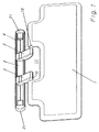
- the carriage points at its edges running in the direction of displacement 3 a plurality of slide strips 12, 13 supported in the guide rail 4 and 14 on. While the slide strips 12 and 13 are rigidly formed on the slide 3 are, the slide strips 14 as outwardly arched spring bridges 15 educated. Between each spring bridge 15 and that adjacent to it There is a window-like free space 16 at the edge of the slide 3 15 form resilient projections.
- springs 17 are arranged in the free spaces.
- the springs 17 are preferably helical compression springs, which are at one end on the spring bridges 15 and elsewhere on the adjacent edges of the carriage 3 support.
Landscapes
- Engineering & Computer Science (AREA)
- Mechanical Engineering (AREA)
- Pivots And Pivotal Connections (AREA)
- Fittings On The Vehicle Exterior For Carrying Loads, And Devices For Holding Or Mounting Articles (AREA)
- Body Structure For Vehicles (AREA)
Abstract
Description
Die Erfindung bezieht sich auf eine Sonnenblende für Kraftfahrzeuge, insbesondere Nutzfahrzeuge, die vornehmlich zur Anordnung im Längsseitenbereich des Fahrerhauses bestimmt ist und einen Sonnenblendenkörper aufweist, der über zwei Lagerböcke verfügt, um eine etwa horizontale Achse verschwenkbar ist und über die Lagerböcke entlang einer zur Schwenkachse parallelen Führungsschiene, die ein im Querschnitt nach der Sichtseite offenes C-förmiges Profil aufweist, verschiebbar geführt ist.The invention relates to a sun visor for motor vehicles, in particular Commercial vehicles, primarily for arrangement in the long side area the driver's cab is determined and has a sun visor body, which has two pedestals, can be pivoted about an approximately horizontal axis is and over the bearing blocks along a parallel to the pivot axis Guide rail that is open in cross-section to the visible side C-shaped profile, is guided.
Bei einer durch die DE 29 25 184 A1 bekanntgewordenen Sonnenblende der gattungsgemäßen Art, haben sich im praktischen Gebrauch Probleme hinsichtlich der Schiebeführung ergeben. Aus Gründen von Toleranzschwankungen, wie auch Wärme- und Kältebelastungen, ist es bei der bekannten Ausführungsform nicht möglich, den Sonnenblendenkörper leichtgängig zu verschieben und dennoch zuverlässig zu verhindern, daß sich der Sonnenblendenkörper ungewollt längs der Führungsschiene verschiebt.In a sun visor which has become known from DE 29 25 184 A1 generic type, have problems in practical use the sliding guide result. For reasons of tolerance fluctuations, as well as heat and cold loads, it is in the known embodiment not possible to move the sun visor body smoothly and yet reliably prevent the sun visor body unintentionally moved along the guide rail.
Der Erfindung liegt hiernach die Aufgabe zugrunde, eine Sonnenblende der eingangs genannten Art qualitätsmäßig zu verbessern und insbesondere Vorsorge dafür zu treffen, daß der Sonnenblendenkörper trotz unvermeidlicher Fertigungstoleranzen und Temperaturbelastungen leichtgängig entlang der Führungsschiene verschiebbar ist, ohne daß eine selbsttätige Verschiebbarkeit möglich ist.The invention is based on the object, a sun visor to improve the quality mentioned at the beginning and in particular preventive measures to ensure that the sun visor body despite inevitable Manufacturing tolerances and temperature loads smoothly along the Guide rail is slidable without an automatic slidability is possible.
Diese Aufgabe wird erfindungsgemäß dadurch gelöst, daß die Lagerböcke mit ihren dem Sonnenblendenkörper abgewandten Enden an einem in der Führungsschiene geführten, aus Kunststoff bestehenden Schlitten angeordnet sind und daß der Schlitten an seinen in der Verschieberichtung verlaufenden Rändern mehrere sich in der Führungsschiene abstützende Gleitleisten aufweist, die an einem dieser Ränder als jeweils einstückig mit dem Schlitten verbundene, nach außen gewölbte Federbrücken ausgebildet sind, wobei sich zwischen jeder Federbrücke und dem benachbarten Schlittenrand ein Freiraum befindet, in dem eine die Federbrücke nach außen belastende Feder angeordnet ist.This object is achieved in that the bearing blocks with their ends facing away from the sun visor body on one in the guide rail guided, made of plastic slides are arranged and that the carriage at its edges running in the direction of displacement has a plurality of slide rails supported in the guide rail, at one of these edges connected as one piece to the slide, spring bridges curved outwards are formed, with between each spring bridge and the adjacent sledge edge have a free space is located in which a spring loading the spring bridge to the outside is arranged is.
Der Einsatz eines aus Kunststoff bestehenden Schlittens verursacht keine nennenswerten Kosten, zumal sich daran die Federbrücken ohne besonderen Aufwand einstückig und materialeinheitlich anformen lassen. Die nach außen gewölbten Federbrücken stellen schon für sich eine wesentliche toleranzausgleichende Qualitätsverbesserung dar, welche noch durch die, jeder Federbrücke zugeordnete Feder optimiert wird, weil eine aus Federstahl oder Federdraht bestehende Feder auf Temperaturbelastungen weit weniger heftig reagiert als eine aus Kunststoff gebildete Federbrücke. Die erfindungsgemäßen Maßnahmen führen zu definierten Reibungsverhältnissen und zum zuverlässigen Ausgleich vorhandener Toleranzen.The use of a slide made of plastic does not cause any noteworthy Costs, especially since the spring bridges without any special Have the work piece molded in one piece and using the same material. The outside arched spring bridges in themselves represent an essential tolerance compensating Quality improvement, which still by the, each spring bridge assigned spring is optimized because one is made of spring steel or spring wire existing spring on temperature loads far less violent reacts as a spring bridge made of plastic. The invention Measures lead to defined friction and reliable Compensation for existing tolerances.
Bevorzugterweise verfügt der Schlitten über zwei nahe seiner Längsenden angeordnete Federbrücken, womit sich eine sichere, verkantungsfreie Verschiebbarkeit ergibt.The carriage preferably has two arranged near its longitudinal ends Spring bridges, which ensures safe, tilt-free displacement results.
Die die Federbrücken belastende Federn sind zweckmäßigerweise Schraubendruckfedern. Solche Federn, die aus Federdraht gebildet sind, lassen sich kostengünstig bereitstellen und auch schnell und einfach montieren.The springs loading the spring bridges are expediently helical compression springs. Such springs, which are formed from spring wire, can be Provide inexpensively and also assemble quickly and easily.
Gemäß einer Weiterbildung der Erfindung kann vorgesehen sein, daß an der Rückseite jeder Federzunge sowie an dem der Federzunge zugewandten Rand jedes Freiraums Zapfen zur Positionierung und Halterung der Federn angeformt sind. According to a development of the invention it can be provided that on the Back of each spring tongue and on the edge facing the spring tongue Each space is molded with a pin for positioning and holding the springs are.
Schließlich kann vorgesehen sein, daß die Führungsschiene endseitige, als Schiebewegbegrenzungsmittel dienende Verriegelungskappen aufweist.Finally, it can be provided that the guide rail ends, as Sliding path limiting means serving locking caps.
Ein Ausführungsbeispiel der Erfindung wird nachfolgend anhand der Zeichnungen näher erläutert, und es zeigen
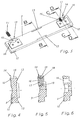
- Fig. 1
- eine Zusammenbauansicht der kompletten Sonnenblende,
- Fig. 2
- eine Explosionsdarstellung der Sonnenblende nach Fig. 1,
- Fig. 3
- eine Einzelheit der Sonnenblende,
- Fig. 4
- einen Schnitt B - B nach Fig. 3,
- Fig. 5
- einen Schnitt C - C nach Fig. 3 und
- Fig. 6
- einen Schnitt D - D nach Fig. 3.
- Fig. 1
- an assembly view of the complete sun visor,
- Fig. 2
- 2 shows an exploded view of the sun visor according to FIG. 1,
- Fig. 3
- a detail of the sun visor,
- Fig. 4
- 4 shows a section BB according to FIG. 3,
- Fig. 5
- a section C - C of Fig. 3 and
- Fig. 6
- a section D - D of FIG. 3rd
Die Sonnenblende nach Fig. 1 umfaßt einen Sonnenblendenkörper 1, zwei
Lagerböcke 2, einen Schlitten 3 und eine den Schlitten 3 aufnehmende Führungsschiene
4.1 comprises a
Wie Fig. 2 erkennen läßt, weist der Sonnenblendenkörper 1 einen aus einem
gebogenen Drahtabschnitt gebildeten Metallrahmen 5 auf. An dem Metallrahmen
5 sind zwei Klemmlager 6 mit je einer Fensteröffnung 7 befestigt.
Die Klemmlager 6 sind jeweils von einer Klemmfeder 8 reiterartig umgriffen
und die U-förmigen Klemmfedern 8 sind untenendig durch aufgesetzte
Klammern 9 gesichert.As can be seen in FIG. 2, the
In die Klemmlager 6 greifen Achsen 10 ein, die an den Lagerböcken 2 angeordnet
sind und die Achsen 10 bilden miteinander eine horizontal ausgerichtete
Drehachse, um die der Sonnenblendenkörper 1 schwenkbar ist. Zweckmäßigerweise
sind die Lagerböcke 2 Kunststoff-Spritzgußkörper mit daran
jeweils einstückig angeformter Achse 10. Die Lageröffnungen der Klemmlager
6 gehen von seitlichen Begrenzungen einer im Längsmittenbereich des
Sonnenblendenkörpers 1 angeordneten Ausnehmung 11 aus, in die die Lagerböcke
2 bereichsweise hineinragen.
Die Lagerböcke 2 sind mit ihren den Achsen 10 abgewandten Endbereichen
mit Hilfe nicht dargestellter Befestigungselemente an dem Schlitten 3 befestigt.
Die Befestigungselemente können z. B. Schrauben sein. The
Der Schlitten 3 ist ein Kunststoff-Spritzgußteil von etwa rechteckiger Form.
An seinen in der Verschieberichtung verlaufenden Rändern weist der Schlitten
3 mehrere sich in der Führungsschiene 4 abstützende Gleitleisten 12, 13
und 14 auf. Während die Gleitleisten 12 und 13 starr am Schlitten 3 angeformt
sind, sind die Gleitleisten 14 als nach außen gewölbte Federbrücken 15
ausgebildet. Zwischen jeder Federbrücke 15 und dem dieser benachbarten
Rand des Schlittens 3 befindet sich ein fensterartiger Freiraum 16. Die Federbrücken
15 bilden federnde Vorsprünge. Zur Unterstützung der Federbrücken
15 sind in den Freiräumen 16 Federn 17 angeordnet. Die Federn 17
sind vorzugsweise Schraubendruckfedern, die sich einendig an den Federbrücken
15 und anderendig an den diesen benachbarten Rändern des Schlittens
3 abstützen. Zur Positionierung und Halterung sind an der Rückseite jeder
Federbrücke 15, wie auch an der diesen gegenüberliegenden Wandung
miteinander fluchtende Zapfen 18, 19 angeformt. Die Zapfen 18, 19 sollten,
wie dargestellt angeschrägt sein, um die Montage zu vereinfachen. Die Federbrücken
15 werden durch die Federn 17 im Verhältnis zu der gewünschten
Schiebekraft unter Spannung gesetzt.The
Der so komplettierte Schlitten 3 wird dann in die Führungsöffnung 20 der
Führungsschiene 4, die z. B. aus Leichtmetall besteht, eingeschoben. Alsdann
wird die Führungsschiene 4 durch Endkappen 21 verriegelt, und zwar
mittels nicht gezeigter Befestigungsschrauben, welche durch einen angeformten
Materiallappen 22 verdeckt werden können. Der Sonnenblendenkörper 1
kann, da der Schlitten 3 wesentlich kürzer als die Führungsschiene 4 ist nun
parallel zur Führungsschiene 4 verschoben und natürlich auch um die beiden
miteinander fluchtenden Achsen 10 verschwenkt werden. Wie Versuche ergeben
haben, genügt die neue Sonnenblende in optimaler Weise den von der
Abnehmerschaft vorgegebenen technischen Anforderungen und wird auch den
ästhetischen Anforderungen der Benutzerschaft vollauf gerecht.The
Claims (5)
Applications Claiming Priority (2)
| Application Number | Priority Date | Filing Date | Title |
|---|---|---|---|
| DE19749795A DE19749795C2 (en) | 1997-11-11 | 1997-11-11 | Sun visors for motor vehicles |
| DE19749795 | 1997-11-11 |
Publications (3)
| Publication Number | Publication Date |
|---|---|
| EP0916533A2 true EP0916533A2 (en) | 1999-05-19 |
| EP0916533A3 EP0916533A3 (en) | 2001-06-13 |
| EP0916533B1 EP0916533B1 (en) | 2002-11-27 |
Family
ID=7848284
Family Applications (1)
| Application Number | Title | Priority Date | Filing Date |
|---|---|---|---|
| EP98116901A Expired - Lifetime EP0916533B1 (en) | 1997-11-11 | 1998-09-08 | Sun visor for motor vehicles |
Country Status (5)
| Country | Link |
|---|---|
| US (1) | US5951089A (en) |
| EP (1) | EP0916533B1 (en) |
| DE (2) | DE19749795C2 (en) |
| ES (1) | ES2189057T3 (en) |
| PL (1) | PL329497A1 (en) |
Families Citing this family (4)
| Publication number | Priority date | Publication date | Assignee | Title |
|---|---|---|---|---|
| US6286887B1 (en) * | 1998-02-23 | 2001-09-11 | M. Anaam Hashmi | Visor with longitudinal movement system |
| DE10224835B4 (en) * | 2002-06-05 | 2005-04-07 | Johnson Controls Interiors Gmbh & Co. Kg | Sun visor for the interior of a motor vehicle |
| US6659528B1 (en) * | 2002-09-18 | 2003-12-09 | Lear Corporation | Method and apparatus for sliding and rotating a vehicle sun visor |
| US9963019B2 (en) * | 2016-05-11 | 2018-05-08 | Ford Global Technologies Llc | Sun visor having extended range of motion |
Citations (1)
| Publication number | Priority date | Publication date | Assignee | Title |
|---|---|---|---|---|
| DE2925184A1 (en) | 1979-06-22 | 1981-01-15 | Daimler Benz Ag | SUN VISOR ARRANGEMENT FOR MOTOR VEHICLES, IN PARTICULAR COMMERCIAL VEHICLES |
Family Cites Families (10)
| Publication number | Priority date | Publication date | Assignee | Title |
|---|---|---|---|---|
| US2583306A (en) * | 1950-04-21 | 1952-01-22 | Celestin A Royer | Windshield visor |
| US3403937A (en) * | 1966-07-19 | 1968-10-01 | Robert L. Quaine | Sun visor construction |
| DE1555949A1 (en) * | 1966-09-29 | 1970-12-10 | Heinz Juelich | Slidable vehicle sun visor |
| US3865428A (en) * | 1972-11-13 | 1975-02-11 | Carroll W Chester | Window shade for a vehicle or the like |
| DE3603852A1 (en) * | 1986-02-07 | 1987-08-13 | Happich Gmbh Gebr | SUN VISOR FOR VEHICLES |
| US5040840A (en) * | 1989-07-10 | 1991-08-20 | Theodor Kokeisl | Glare protection device for motor vehicle passengers |
| US5158334A (en) * | 1989-07-17 | 1992-10-27 | Felland Raymond G | Adjustable vehicular glare shielding device |
| US5484183A (en) * | 1995-01-05 | 1996-01-16 | Rosa; Thomas F. | Adjustable sun visor attachment |
| US5538310A (en) * | 1995-04-24 | 1996-07-23 | Prince Corporation | Track visor |
| US5678880A (en) * | 1996-10-28 | 1997-10-21 | Keller; Lucius W. | Visor extender |
-
1997
- 1997-11-11 DE DE19749795A patent/DE19749795C2/en not_active Expired - Fee Related
-
1998
- 1998-09-08 ES ES98116901T patent/ES2189057T3/en not_active Expired - Lifetime
- 1998-09-08 DE DE59806433T patent/DE59806433D1/en not_active Expired - Lifetime
- 1998-09-08 EP EP98116901A patent/EP0916533B1/en not_active Expired - Lifetime
- 1998-11-04 PL PL98329497A patent/PL329497A1/en unknown
- 1998-11-11 US US09/189,885 patent/US5951089A/en not_active Expired - Lifetime
Patent Citations (1)
| Publication number | Priority date | Publication date | Assignee | Title |
|---|---|---|---|---|
| DE2925184A1 (en) | 1979-06-22 | 1981-01-15 | Daimler Benz Ag | SUN VISOR ARRANGEMENT FOR MOTOR VEHICLES, IN PARTICULAR COMMERCIAL VEHICLES |
Also Published As
| Publication number | Publication date |
|---|---|
| PL329497A1 (en) | 1999-05-24 |
| US5951089A (en) | 1999-09-14 |
| EP0916533A3 (en) | 2001-06-13 |
| DE59806433D1 (en) | 2003-01-09 |
| ES2189057T3 (en) | 2003-07-01 |
| DE19749795C2 (en) | 2002-11-14 |
| EP0916533B1 (en) | 2002-11-27 |
| DE19749795A1 (en) | 1999-05-20 |
Similar Documents
| Publication | Publication Date | Title |
|---|---|---|
| DE10115124C2 (en) | Security device for a door window of a motor vehicle | |
| DE112018000009B4 (en) | Longitudinal adjuster for a vehicle seat and vehicle seat | |
| DE19514585C2 (en) | Sliding element for a link part of a sliding / lifting roof of a motor vehicle | |
| DE2511201A1 (en) | CONCEALED HINGE FOR DOOR LEAF, PRIORLY FURNITURE HINGE | |
| DE3313327C2 (en) | ||
| EP0916533B1 (en) | Sun visor for motor vehicles | |
| DE3312470C2 (en) | ||
| DE2205147A1 (en) | Guide mechanism for motor vehicle sash windows | |
| DE7701194U1 (en) | WINDOWS, IN PARTICULAR FOR A MOTOR VEHICLE BODY | |
| DE102011102718A1 (en) | Slider unit for supporting a movable roof element of a vehicle roof and vehicle roof | |
| DE4437661A1 (en) | Adjuster for wheel suspension arm w.r.t. its mounting | |
| EP0897817B1 (en) | Sun visor for vehicle | |
| DE9201801U1 (en) | Drawer with a support rail | |
| DE3623073C2 (en) | ||
| DE3141243A1 (en) | System for the guidance and fixing of fittings | |
| DE10205118A1 (en) | Guide apparatus for vehicle roof component, has transmission member which slides along guide running-path in horizontal direction, covering predetermined distance with respect to guide running path | |
| DE4126442C1 (en) | ||
| DE9307599U1 (en) | Window regulators, especially for convertible vehicles | |
| DE2719890A1 (en) | Adjustable hinge for furniture components - has longitudinal and vertical adjustment using guide profile with flexible key | |
| DE102019208772A1 (en) | Fastening arrangement for a window slot strip | |
| DE4342758C2 (en) | Door for vehicle body | |
| DE2537536A1 (en) | WINDOW GUIDE, ESPECIALLY FOR MOTOR VEHICLES | |
| DE1911843A1 (en) | Window guide for the sliding window of a motor vehicle | |
| DE3718840C1 (en) | Window lifter for motor vehicles | |
| EP0761512B1 (en) | Motor vehicle with height adjustable return loop fitting for its safety belts |
Legal Events
| Date | Code | Title | Description |
|---|---|---|---|
| PUAI | Public reference made under article 153(3) epc to a published international application that has entered the european phase |
Free format text: ORIGINAL CODE: 0009012 |
|
| AK | Designated contracting states |
Kind code of ref document: A2 Designated state(s): DE ES FR GB IT NL SE |
|
| AX | Request for extension of the european patent |
Free format text: AL;LT;LV;MK;RO;SI |
|
| RAP1 | Party data changed (applicant data changed or rights of an application transferred) |
Owner name: JOHNSON CONTROLS INTERIORS GMBH & CO. KG |
|
| PUAL | Search report despatched |
Free format text: ORIGINAL CODE: 0009013 |
|
| AK | Designated contracting states |
Kind code of ref document: A3 Designated state(s): AT BE CH CY DE DK ES FI FR GB GR IE IT LI LU MC NL PT SE |
|
| AX | Request for extension of the european patent |
Free format text: AL;LT;LV;MK;RO;SI |
|
| 17P | Request for examination filed |
Effective date: 20010521 |
|
| AKX | Designation fees paid |
Free format text: DE ES FR GB IT NL SE |
|
| GRAG | Despatch of communication of intention to grant |
Free format text: ORIGINAL CODE: EPIDOS AGRA |
|
| GRAG | Despatch of communication of intention to grant |
Free format text: ORIGINAL CODE: EPIDOS AGRA |
|
| GRAH | Despatch of communication of intention to grant a patent |
Free format text: ORIGINAL CODE: EPIDOS IGRA |
|
| 17Q | First examination report despatched |
Effective date: 20020529 |
|
| GRAH | Despatch of communication of intention to grant a patent |
Free format text: ORIGINAL CODE: EPIDOS IGRA |
|
| GRAA | (expected) grant |
Free format text: ORIGINAL CODE: 0009210 |
|
| AK | Designated contracting states |
Kind code of ref document: B1 Designated state(s): DE ES FR GB IT NL SE |
|
| REG | Reference to a national code |
Ref country code: GB Ref legal event code: FG4D Free format text: NOT ENGLISH |
|
| REF | Corresponds to: |
Ref document number: 59806433 Country of ref document: DE Date of ref document: 20030109 |
|
| GBT | Gb: translation of ep patent filed (gb section 77(6)(a)/1977) |
Effective date: 20030315 |
|
| ET | Fr: translation filed | ||
| REG | Reference to a national code |
Ref country code: ES Ref legal event code: FG2A Ref document number: 2189057 Country of ref document: ES Kind code of ref document: T3 |
|
| PLBE | No opposition filed within time limit |
Free format text: ORIGINAL CODE: 0009261 |
|
| STAA | Information on the status of an ep patent application or granted ep patent |
Free format text: STATUS: NO OPPOSITION FILED WITHIN TIME LIMIT |
|
| 26N | No opposition filed |
Effective date: 20030828 |
|
| PGFP | Annual fee paid to national office [announced via postgrant information from national office to epo] |
Ref country code: GB Payment date: 20040817 Year of fee payment: 7 |
|
| PGFP | Annual fee paid to national office [announced via postgrant information from national office to epo] |
Ref country code: NL Payment date: 20040819 Year of fee payment: 7 |
|
| PG25 | Lapsed in a contracting state [announced via postgrant information from national office to epo] |
Ref country code: GB Free format text: LAPSE BECAUSE OF NON-PAYMENT OF DUE FEES Effective date: 20050908 |
|
| PG25 | Lapsed in a contracting state [announced via postgrant information from national office to epo] |
Ref country code: NL Free format text: LAPSE BECAUSE OF NON-PAYMENT OF DUE FEES Effective date: 20060401 |
|
| GBPC | Gb: european patent ceased through non-payment of renewal fee |
Effective date: 20050908 |
|
| NLV4 | Nl: lapsed or anulled due to non-payment of the annual fee |
Effective date: 20060401 |
|
| PGFP | Annual fee paid to national office [announced via postgrant information from national office to epo] |
Ref country code: DE Payment date: 20140922 Year of fee payment: 17 |
|
| PGFP | Annual fee paid to national office [announced via postgrant information from national office to epo] |
Ref country code: FR Payment date: 20140919 Year of fee payment: 17 Ref country code: SE Payment date: 20140918 Year of fee payment: 17 Ref country code: ES Payment date: 20140923 Year of fee payment: 17 |
|
| PGFP | Annual fee paid to national office [announced via postgrant information from national office to epo] |
Ref country code: IT Payment date: 20140924 Year of fee payment: 17 |
|
| REG | Reference to a national code |
Ref country code: DE Ref legal event code: R119 Ref document number: 59806433 Country of ref document: DE |
|
| PG25 | Lapsed in a contracting state [announced via postgrant information from national office to epo] |
Ref country code: IT Free format text: LAPSE BECAUSE OF NON-PAYMENT OF DUE FEES Effective date: 20150908 |
|
| REG | Reference to a national code |
Ref country code: SE Ref legal event code: EUG |
|
| PG25 | Lapsed in a contracting state [announced via postgrant information from national office to epo] |
Ref country code: SE Free format text: LAPSE BECAUSE OF NON-PAYMENT OF DUE FEES Effective date: 20150909 |
|
| REG | Reference to a national code |
Ref country code: FR Ref legal event code: ST Effective date: 20160531 |
|
| PG25 | Lapsed in a contracting state [announced via postgrant information from national office to epo] |
Ref country code: DE Free format text: LAPSE BECAUSE OF NON-PAYMENT OF DUE FEES Effective date: 20160401 |
|
| PG25 | Lapsed in a contracting state [announced via postgrant information from national office to epo] |
Ref country code: FR Free format text: LAPSE BECAUSE OF NON-PAYMENT OF DUE FEES Effective date: 20150930 |
|
| REG | Reference to a national code |
Ref country code: ES Ref legal event code: FD2A Effective date: 20161028 |
|
| PG25 | Lapsed in a contracting state [announced via postgrant information from national office to epo] |
Ref country code: ES Free format text: LAPSE BECAUSE OF NON-PAYMENT OF DUE FEES Effective date: 20150909 |