EP0916578A2 - Maschine zum Verpacken von Maschenware, insbesondere von Feinstrick- und Strickstrumpfhosen, -kniestrümpfen, -socken und dgl., in Beuteln - Google Patents
Maschine zum Verpacken von Maschenware, insbesondere von Feinstrick- und Strickstrumpfhosen, -kniestrümpfen, -socken und dgl., in Beuteln Download PDFInfo
- Publication number
- EP0916578A2 EP0916578A2 EP98121514A EP98121514A EP0916578A2 EP 0916578 A2 EP0916578 A2 EP 0916578A2 EP 98121514 A EP98121514 A EP 98121514A EP 98121514 A EP98121514 A EP 98121514A EP 0916578 A2 EP0916578 A2 EP 0916578A2
- Authority
- EP
- European Patent Office
- Prior art keywords
- bag
- bags
- mouth
- machine according
- magazine
- Prior art date
- Legal status (The legal status is an assumption and is not a legal conclusion. Google has not performed a legal analysis and makes no representation as to the accuracy of the status listed.)
- Withdrawn
Links
Images


Classifications
-
- B—PERFORMING OPERATIONS; TRANSPORTING
- B65—CONVEYING; PACKING; STORING; HANDLING THIN OR FILAMENTARY MATERIAL
- B65B—MACHINES, APPARATUS OR DEVICES FOR, OR METHODS OF, PACKAGING ARTICLES OR MATERIALS; UNPACKING
- B65B25/00—Packaging other articles presenting special problems
- B65B25/20—Packaging garments, e.g. socks, stockings, shirts
-
- B—PERFORMING OPERATIONS; TRANSPORTING
- B65—CONVEYING; PACKING; STORING; HANDLING THIN OR FILAMENTARY MATERIAL
- B65B—MACHINES, APPARATUS OR DEVICES FOR, OR METHODS OF, PACKAGING ARTICLES OR MATERIALS; UNPACKING
- B65B43/00—Forming, feeding, opening or setting-up containers or receptacles in association with packaging
- B65B43/26—Opening or distending bags; Opening, erecting, or setting-up boxes, cartons, or carton blanks
- B65B43/28—Opening or distending bags; Opening, erecting, or setting-up boxes, cartons, or carton blanks by grippers co-operating with fixed supports
-
- B—PERFORMING OPERATIONS; TRANSPORTING
- B65—CONVEYING; PACKING; STORING; HANDLING THIN OR FILAMENTARY MATERIAL
- B65B—MACHINES, APPARATUS OR DEVICES FOR, OR METHODS OF, PACKAGING ARTICLES OR MATERIALS; UNPACKING
- B65B43/00—Forming, feeding, opening or setting-up containers or receptacles in association with packaging
- B65B43/26—Opening or distending bags; Opening, erecting, or setting-up boxes, cartons, or carton blanks
- B65B43/34—Opening or distending bags; Opening, erecting, or setting-up boxes, cartons, or carton blanks by internal pressure
- B65B43/36—Opening or distending bags; Opening, erecting, or setting-up boxes, cartons, or carton blanks by internal pressure applied pneumatically
Definitions
- the present invention relates to a bag filling machine for packaging small knitwear items in bags, particularly for packaging hosiery items.
- packaging machines which partially fold these items and insert them in bags. Although these machines allow to perform packaging automatically, thus limiting the manual operations, they have the drawback of having a complex structure with consequent high production costs.
- the aim of the present invention is to solve the above problems, providing a bag filling machine for packaging small knitwear items in bags, particularly for packaging hosiery items, which is capable of performing packaging automatically.
- an object of the invention is to provide a bag filling machine which fully eliminates, or considerably limits, manual operations and therefore significantly reduces labor-related costs for the packaging operation.
- Another object of the invention is to provide a packaging machine which is highly precise and reliable in operation.
- a bag filling machine for packaging small knitwear items in bags, particularly for packaging hosiery items, characterized in that it comprises: feeder means for feeding items to be packaged to a packaging station; a bag magazine arranged at said packaging station; means for opening the mouth of one of the bags carried by said magazine; pick-up and insertion means for picking up the items to be packaged from said feeder means and for inserting them through the open mouth of said bag; and means for removing said bag, with the item inserted therein, from said packaging station.
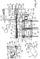
- the bag filling machine comprises: means 2 for feeding the items 3 to be packaged to a packaging station 4; a magazine 5 for bags 6, which is arranged at the packaging station 4; means for opening the mouth 6a of one of the bags 6 carried by the magazine 5; pick-up and insertion means 7 for picking up the items 3 to be packaged from the feeder means 2 and for inserting them through the open mouth 6a of the bag 6; and means 8 for moving the bag 6, with the item 3 inserted therein, away from the packaging station 4.
- a tab 6b which protrudes from one of the sides of the mouth 6a.
- the tab 6b also has two holes 6c which are spaced from the mouth 6a and are meant to be engaged by a pair of bars 10a and 10b which are located proximate to the magazine 5, as will become apparent hereinafter.
- Prefracture lines 6d constituted for example by discontinuous cuts formed during the production of the bag 6, run from the holes 6c to the edge of the tab 6b that lies opposite with respect to the mouth 6a.
- the feeder means 2 comprise a conveyor formed by a plurality of narrow belts 11 which are arranged mutually side by side, lie parallel to an advancement direction, shown by the arrow 12 in Figure 1, and surround two rollers 13a and 13b which are supported, so that they can rotate about their respective horizontal axes, which are perpendicular to the advancement direction 12, by the supporting structure 14 of the machine, which is shown only partially in the figures.
- the rollers 13a and 13b are arranged so that the upper portion of the belts 11 is arranged on a substantially horizontal plane and forms a supporting surface for the items 3 to be packaged.
- the output end of the belt conveyor 11, formed by the roller 13b, is arranged at the beginning of the packaging station 4.
- At least one of the rollers 13a and 13b can be rotationally actuated about its own axis, for example by means of an electric motor, in order to produce an advancement of the items 3 arranged on the upper portion of the belts 11 toward the packaging station 4.
- the magazine 5 is adapted to support a stack of bags 6 arranged on substantially horizontal planes and orientated so that their mouth 6a faces the belt conveyor of the feeder means 2.
- the magazine 5 comprises a supporting frame 30, which is fixed to the supporting structure 14 of the machine and is provided with an upper cross-member 31 and with a lower cross-member 32, both of which are fixed to the supporting structure 14 of the machine.
- the frame 30 also supports a bottom 33 which is fixed to the top of vertical posts 34 which are supported, so that they can slide in a vertical direction, by the cross-members 31 and 32 of the frame 30.
- the frame 30 also supports a plurality of vertical rods 35 which rise vertically and delimit in a lateral region, i.e., transversely to the advancement direction 12, a compartment 36 which is delimited in a downward region by the bottom 33.
- the compartment 36 is open in an upward region and the upper ends of the vertical rods 35 that are arranged on a same side of the compartment 36 are joined by a shoulder 37, 38 which lies parallel to the advancement direction 12.
- the shoulders 37 and 38 form an upper stop element for the bag 6 arranged at the upper end of the stack of bags.
- the lower cross-member 32 also supports a gearmotor 39 which is connected, by means of its output shaft, to a vertical threaded shaft 40 which is supported, so that it can rotate about its axis, by the frame 30 and engages a female thread formed in a block 41 which is rigidly coupled to the bottom 33 of the magazine 5.
- the actuation of the gearmotor 39 causes the gradual upward movement of the bottom 33 so as to place the bag 6, that is arranged at the upper end of the stack of bags placed in the compartment 36, on the plane of the translatory motion of the pick-up and insertion means 7, which will be described in greater detail hereinafter.
- the vertical rods 35 that support the shoulders 37 and 38 are mounted on two lateral blocks 42a and 42b which are mounted so that they can slide along two horizontal guiding bars 43a and 43b which are arranged at right angles to the advancement direction 12 and are fixed to two shoulders 15a and 15b of the supporting structure 14, which lie laterally to the magazine 5 and are parallel to the advancement direction 12.
- a female thread is formed in the lateral blocks 42a and 42b and is engaged by a threaded shaft 44 which is parallel to the guiding bars 43a and 43b, is supported so as to be able to rotate about its own axis by the shoulders 15a and 15b of the supporting structure 14, and is fixed to a knob 45 with one of its ends. Turning the knob 45 produces the translatory motion of the lateral blocks 42a and 42b and therefore of the rods 35 and of the shoulders 37 and 38 toward or away from each other. The translatory motion of the rods 35 is allowed by adapted slots 46 formed in the bottom 33, which are crossed by the rods 35 and are elongated at right angles to the advancement direction 12.
- the retention means comprise two vertical bars 10a and 10b which are fixed to the supporting structure 14 of the machine and are meant to pass through the holes 6c of the tabs 6c of the bags 6 that are stacked and arranged in the compartment 36 of the magazine 5 on substantially horizontal planes and so that the side of the mouth 6a of the bags 6 that is not provided with the tab 6b faces upwards.
- the means for opening the mouth 6a of one of the bags carried by the magazine 5 comprise at least one sucker 90, which is shown only in Figures 2, 4, 9, 11 and 13 for the sake of greater clarity, is arranged at the packaging station 4 and is connected to suction means 91.
- the sucker 90 can move on command towards and away from the bag 6 to engage one side of the mouth 6a of the bag 6 and space it from the opposite side of the mouth 6a, thus opening it.
- the sucker 90 is connected to the end of the stem 92a of the piston of a pneumatic cylinder 92 which has a vertical axis and is arranged above the stack of bags 6 carried by the magazine 5 so that the sucker 90 faces the upper side, which does not have the tab 6b, of the mouth 6a of the bag 6 which, in each instance, is located at the top of the stack of bags 6 carried by the magazine 5.
- the pneumatic cylinder 92 can be actuated in order to lower and raise the sucker 90 and thus make it engage the upper side of the mouth 6a of the bag 6 and space it from the lower side, which is retained, by means of the tab 6b, by the bars 10a and 10b and by a plate 17 which rests on said tab 6b.
- the pneumatic cylinder 92 is supported by an arm 93 which is pivoted to the supporting structure 14 about a horizontal axis 94 which is perpendicular to the direction 12, so that it can be turned over at least partially in order to allow to load the bags 6 in the magazine 5 and install and remove said magazine 5.
- the sucker 90 is connected to a Venturi device or in any case to a conventional suction device which is not described further for the sake of simplicity.
- the sucker 90 ensures high precision and reliability in opening the bags 6 used for packaging even in the presence of electrostatic charges which contrast the opening action if bags made of synthetic material are used.
- the means for opening the mouth 6a of one of the bags 6 carried by the magazine 5 also comprise means for dispensing a jet of air, which are arranged between the output end of the feeder means 2 and the stack of bags 6 carried by the magazine 5.
- the air jet dispensing means are conveniently constituted by one or more nozzles 16 which are directed toward the mouth 6a of the top bag 6 of the stack and are formed in the plate 17 which is pivoted to the shoulders 15a and 15b of the supporting structure 14.
- the plate 17 can rotate about its own pivoting axis 17a, which is arranged horizontally and is perpendicular to the advancement direction 12.
- the plate 17 can rotate about the pivoting axis 17a to pass from an active position, in which it is arranged on a substantially horizontal plane and is superimposed on the tabs 6b of the stack of bags 6 so that the nozzles 16 are directed toward the mouth 6a of the bag 6 arranged at the upper end of the stack, to a loading position, in which it is arranged on a substantially vertical plane to allow the insertion of a new stack of bags in the compartment 36.
- the arc of the rotation of the plate 17 is delimited by an appropriately provided slot 28 which is shaped like a circular arc centered on the axis 17a and is formed in a portion of one of the shoulders 15a and 15b; a pin of the plate 17 engages the slot 28.
- the plate 17 can be locked in the active position by means of an adapted knob 29.
- the means for opening the mouth 6a of the bags 6 also comprise two secondary arms 18a and 18b which can be inserted on command through the mouth 6a of the bag 6 arranged at the top of the stack of bags in the magazine 5, after the mouth 6a has been opened by the sucker 90 and by the air jet delivered by the nozzle or nozzles 16.
- the secondary arms 18a and 18b are fixed to respective shafts 19a and 19b which are supported so that they can rotate about their own axes by the supporting structure 14 of the machine.
- the shafts 19a and 19b are arranged laterally, on opposite sides, with respect to the stack of bags 6 carried by the magazine 5 and have vertically orientated axes.
- the secondary arms 18a and 18b lie transversely with respect to the shafts 19a and 19b, which are connected to the output shaft of respective electric motors 20a and 20b, preferably electric step motors, which can be actuated so as to produce the rotation of the shafts 19a and 19b about their respective axes through a preset angle, preferably 90°, in order to move the secondary arms 18a and 18b from an inactive position, in which the secondary arms 18a and 18b face each other and are parallel and arranged in front of the mouth 6a of the bags 6, i.e., at right angles to the advancement direction 12, to an insertion position, in which they are inserted in the mouth 6a of the bag 6, which is opened by the sucker 90 and by the air jet delivered by the nozzle 16, and are arranged parallel to the two sides of the bag that extend from the mouth 6a.
- a preset angle preferably 90°
- the shafts 19a and 19b and the motors 20a and 20b that actuate them are fitted on blocks 70a and 70b which are mounted so that they can slide on horizontal guiding bars 71a and 71b which are fixed to the shoulders 15a and 15b of the supporting structure 14 and are arranged at right angles to the advancement direction 12.
- a female thread is formed in the blocks 70a and 70b and mates with a horizontal threaded shaft 72 which is perpendicular to the advancement direction 12 and is rigidly coupled to a knob 73 which is supported by the supporting structure 14 of the machine.
- the blocks 70a and 70b are made to perform a translatory motion along the guiding bars 71a and 71b and therefore the shafts 19a and 19b are made to perform a translatory motion towards or away from each other.
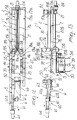
- the pick-up and insertion means 7 comprise a fork-shaped element with three prongs 7a, 7b and 7c which are arranged side by side, are parallel to the advancement direction 12 and are interposed between the belts 11.
- the prongs 7a, 7b and 7c are joined, at their opposite end with respect to the packaging station 4, by a block 21.
- the fork-like element is arranged on a substantially horizontal plane and can move on command, along the advancement direction 12, from a standby position, in which it is arranged so that its prongs 7a, 7b and 7c lie between the belts 11, to an insertion position, in which it is made to perform a translatory motion into the bag 6 through the mouth 6a opened by said opening means.
- the block 21 is slidingly supported by two guides 22a and 22b which are fixed to the supporting structure 14 of the machine and are parallel to the advancement direction 12.
- a female thread is formed in the block 21 and couples to a threaded shaft 23 which is parallel to the guides 22a and 22b and is supported, so as to be able to rotate about its own axis, by the supporting structure 14.
- the threaded shaft 23 is fixed to the output shaft of an electric motor 24 which can be actuated so as to produce the translatory motion, in one direction or in the opposite direction, of the block 21 along the guides 22a and 22b to move the fork-like element from the standby position to the insertion position or vice versa.
- the prong 7c arranged between the prongs 7a and 7b, is shorter than the prongs 7a and 7b.
- the upper side of the prongs 7a, 7b and 7c which is meant to make contact with the items 3 to move them into the bag 6, is preferably covered with a layer of material with enhanced grip, such as for example felt or the like.
- the prongs 7a and 7b of the fork-like element rest on the roller 13b, as shown in particular in Figures 2 and 4 and, like the intermediate prong 7c, are arranged on a horizontal plane which is slightly lower than the supporting surface formed by the upper portion of the belts 11, so as to avoid hindering the advancement of the items 3 along the belt conveyor 11.
- the lower face of the free end of the prongs 7a, 7b and 7c is shaped like an inclined plane, so that the passage of the fork-like element from the standby position to the insertion position also achieves an upward movement of the prongs 7a, 7b and 7c which is sufficient to raise the items 3 located on the end portion of the belt conveyor 11 from said belts 11.
- the upward movement of the prongs 7a, 7b and 7c is allowed by the elastic flexing of said prongs 7a, 7b and 7c with respect to the block 21.
- the fork-like element can move substantially on a horizontal plane which substantially coincides with the plane on which the upper bag of the stack of bags 6 supported by the magazine 5 is arranged, and its advancement stroke in passing from the standby position to the insertion position, after the free ends of the prongs 7a, 7b and 7c have passed through the mouth 6a of the bag 6, is greater than the distance between the mouth 6a and the bottom of the bag 6 so as to produce, at the end of the advancement stroke, the disengagement of the tab 6b of the bag 6 from the bars 10a and 10b by means of the tearing of the tab 6b along the prefracture lines 6d.
- the pick-up and insertion means also comprise presser means which act on the items 3 to be packaged in order to press them before they are inserted into the bag 6.
- the presser means comprise at least one flap 81 which is associated with the fork-like element and faces in an upward region the prongs of the fork-like element.
- a flap 81 which lies so as to overlap the central prong 7c of the fork-like element.
- the flap 81 is fixed, by means of one of its longitudinal ends, to a block 82 which is supported by the block 21 so that it can move in a substantially vertical direction.
- the block 82 which supports the flap 81, is slidingly supported by two vertical guides 83a and 83b which are fixed to the block 21.
- An electric motor 84 preferably a step motor, is mounted on the block 21 and is connected, by means of its output shaft, to a vertical threaded shaft 85 which couples to a female thread formed in the block 82.
- the block 82 By actuating the motor 84 so that it rotates in one direction, the block 82 is lowered and therefore the flap 81 is also lowered, pressing against the items 3 supported by the prongs 7a, 7b and 7c of the fork-like element, while actuating the motor 84 in the opposite direction of rotation lifts the block 82 and therefore the flap 81, which moves away in an upward direction from the prongs of the fork-like element.
- the presser means by compressing the items 3 before and during their insertion in the bag 6, allow to perform without problems the packaging of items whose thicknesses differ considerably.
- Said detection means 25 can be constituted for example by a photocell 26 which cooperates with a reflector plate 27 which is applied to a region of the upper face of the prong 7c of the fork-like element which, when the fork-like element is in the standby position, is located below the photocell 26.
- Said detection means 25 are operatively connected to the motor 24 so as to move the fork-like element from the standby position to the insertion position when an item 3 is detected below the photocell 26.
- the flap 81 is suitably shorter than the central prong 7c of the fork-like element, so that it does not interfere, when it is spaced in an upward region from the prongs of the fork-like element, with the photocell 26 and does not cover the reflector plate 27.
- Said cutting means comprise a guillotine blade 51 which is fixed to a frame 52 which is slideable on command along vertical guides 53a and 53b.
- Actuation means act on the frame 52 and produce its translatory motion along the guides 53b and 53b.
- Said actuation means can be constituted by an electric motor 54 which is connected to the frame 52 with a system of the nut-and-screw type, as already described with reference to the actuation of the fork-like element, or can be constituted by a fluid-actuated cylinder according to the requirements.
- downstream of the packaging station 4 in the advancement direction 12 there are also means 55 for closing the mouth 6a of the bag.
- the closure means 55 can be constituted, if the bag 6 is made of heat-sealable synthetic material, by a blade 56 which is conveniently heated in a per se known manner and is associated with the frame 52 directly downstream of the blade 51 so that the actuation of the motor 54 produces both the cutting of the tab 6b and the closure heat-sealing of the mouth 6a of the bag 6.
- the means 8 for removing the bag 6 with the packaged item 3 comprise a gripper element 60 which is associated with a block 61 which is slidingly supported by two guides 62a and 62b which are parallel to the advancement direction 12 and are fixed to the supporting structure 14 of the machine directly downstream of the cutting means 50 in the advancement direction 12.
- the gripper element 60 can be open, i.e., moved into the release position, or closed, i.e., moved into the grip position, by a fluid-actuated cylinder 80 or by another technically equivalent actuation element which is mounted on the block 61.
- a female thread is formed in the block 61 and a threaded shaft 63 engages therewith; the shaft 63 is parallel to the guides 62a and 62b and is supported, so that it can rotate about its own axis, by the supporting structure 14 of the machine.
- the threaded shaft 63 is fixed to the output shaft of an electric motor 64 which can be actuated so as to produce the translatory motion, in one direction or in the opposite direction, of the block 61 along the guides 62a and 62b.
- Three positions for the gripper element 60 are provided along the guides 62a and 62b: a receiving position, in which it is arranged directly downstream of the cutting means 50; an intermediate position, in which it is moved further downstream of the cutting means 50 with respect to the receiving position; and a stroke limit position, in which it is spaced further downstream with respect to the intermediate position in the advancement direction 12.
- the gripper element 60 In the receiving position, the gripper element 60 is positioned, in the open condition, directly downstream of the cutting means 50 so as to receive, between its two jaw, the bottom of the bag 6 which is pushed by the fork-like element.
- the gripper element 60 is arranged, and has appropriate dimensions, so as to engage in the region of the bottom of the bag between the two prongs 7a and 7b of the fork-like element, i.e., in the central region of the bottom of the bag, which is free since the prong 7c is shorter, as mentioned, than the prongs 7a and 7b.
- the distance between the intermediate position and the receiving position of the gripper element 60 is such that when the gripper element 60 engages the bottom of the bag 6 and is arranged in the intermediate position, the bag 6 is arranged so that its mouth 6a lies at the blade 51.
- the fork-like element of the pick-up and insertion means 7 is in the standby position; i.e., the free ends of its prongs 7a and 7b rest on the roller 13b, while the gripper element 60 is open in the receiving position.
- the flap 81 of the presser means is spaced in an upward region with respect to the plane of arrangement of the prongs 7a, 7b and 7c of the fork-like element and the secondary arms 18a and 18b are in the inactive position, i.e., they face each other at right angles to the advancement direction 12 ( Figures 1 and 2).
- the items 3 to be packaged are arranged sequentially on the initial portion of the belt conveyor 11.
- the actuation of the belts 11 produces the sequential advancement of the items 3 toward the packaging station 4.
- the sucker 90 is actuated, separating the upper side from the lower side of the mouth 6a of the bag 6 which is arranged at the upper end of the stack of bags 6 carried by the magazine 5; then the nozzle 16 is actuated, completing the opening of the mouth 6a of the bag 6.
- the step motors 20a and 20b are actuated so as to move the secondary arms 18a and 18b into the insertion position, in which, as mentioned, they are inserted through the mouth 6a of the bag 6 in order to keep it open.
- the sucker 90 is deactivated, i.e., its connection to the suction means 91 is interrupted, and said sucker is raised above the bag so as to avoid hindering the subsequent operations of the machine.
- the motor 84 When the first of the items 3 arrives below the photocell 26, the motor 84 is actuated, lowering the flap 81 and consequently pressing the items 3; then the motor 24 is actuated, causing the translatory motion of the fork-like element toward the packaging station 4.
- the fork-like element rises above the supporting surface formed by the upper portion of the belts 11 so as to pick up the item 3 located below the photocell 26 from said belts.
- the translatory motion of the fork-like element gradually inserts the items 3 in the bag 6 ( Figures 8 and 9), and at the end of its stroke the fork-like element produces the separation of the bag 6 from the magazine 5, placing the bottom of the bag 6 between the two jaws of the gripper element 60.
- the gripper element 60 is closed so as to grip the bottom of the bag 6 ( Figures 10 and 11), also gripping the end of the items 3 located in that region.
- the motor 84 is then actuated so as to rotate in reverse with respect to the previous direction of rotation, so as to partially lift the flap 81 off the prongs of the fork-like element in order to disengage it from the items 3 without damaging the bag 6.
- the motor 64 is actuated, causing the transfer of the gripper element 60 from the receiving position to the intermediate position.
- the mouth 6a of the bag is arranged at the blade 51, which is actuated so as to remove the tab 6b and optionally perform the heat-sealing of the mouth 6a of the bag 6 by means of the heated blade 56 ( Figures 12 and 13).
- the motor 64 is again actuated so as to move the gripper element 60 into the stroke limit position, in which it is opened by the fluid-actuated cylinder 80, allowing the bag 6 to fall, together with the packaged item 3 inside it, into a collecting container or onto a conveyor belt according to the requirements.
- the motor 64 While the motor 64 is actuated in order to move the gripper element 60 from the receiving position to the intermediate position, the motor 24 is also actuated in reverse with respect to the preceding direction of rotation, so as to return the fork-like element of the pick-up and insertion means 7 to the initial position.
- the lifting of the flap 81 is then completed by virtue of the actuation of the motor 84 and the motors 20a and 20b are then also actuated in order to return the secondary arms 18a and 18b to the inactive position.
- the motor 64 is again actuated in reverse with respect to the previous direction of rotation so as to return the gripper element 60 to the receiving position.
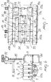
- FIGs 14 and 15 illustrate a different embodiment of the machine according to the invention, generally designated by the reference numeral 101, in which the stack of bags 6 is supported above the plane on which the fork-like element performs its translatory motion instead of therebelow.
- the bags 6 are again coupled to the magazine, or rather to the bars 10a and 10b, by means of their tab 6b, which in this arrangement of the bags protrudes from the upper side of their mouth 6a.
- the stack of bags 6 rests on a supporting plate 133 which is substantially horizontal and is arranged directly below the plane on which the fork-like element performs its translatory motion, and the means for opening the mouth act, in each instance, on the mouth 6a of the bag 6 that is located at the lower end of the stack of bags.
- the elements that correspond to the elements that have already been described in the embodiment illustrated in Figures 1 to 13 have been designated by the same reference numerals.
- the machine according to the invention fully achieves the intended aim, since it is capable of packaging small knitwear items, particularly hosiery items, in bags in a fully automatic manner and with high precision and reliability.
- Another advantage of the machine according to the invention is its long period of unattended operation, achieved by means of the magazine, which can contain a large number of bags.
- the materials used, as well as the dimensions, may be any according to the requirements and the state of the art.
Landscapes
- Engineering & Computer Science (AREA)
- Mechanical Engineering (AREA)
- Supplying Of Containers To The Packaging Station (AREA)
Applications Claiming Priority (6)
| Application Number | Priority Date | Filing Date | Title |
|---|---|---|---|
| ITMI972553 | 1997-11-17 | ||
| IT002553 IT1296448B1 (it) | 1997-11-17 | 1997-11-17 | Macchina insacchettatrice per il confezionamento di articoli di maglieria di piccole dimensioni in sacchetti, particolarmente per il |
| ITMI980127 | 1998-01-23 | ||
| ITMI980127 IT1298196B1 (it) | 1998-01-23 | 1998-01-23 | Macchina insacchettatrice per il confezionamento di articoli di maglieria di piccole dimensioni in sacchetti, particolarmente per il |
| ITMI980906 ITMI980906A1 (it) | 1998-04-28 | 1998-04-28 | Macchina insacchettatrice per il confezionamento di articoli di maglieria di piccole dimensioni in sacchetti particolarmente per il |
| ITMI980906 | 1998-04-28 |
Publications (1)
| Publication Number | Publication Date |
|---|---|
| EP0916578A2 true EP0916578A2 (de) | 1999-05-19 |
Family
ID=27274091
Family Applications (1)
| Application Number | Title | Priority Date | Filing Date |
|---|---|---|---|
| EP98121514A Withdrawn EP0916578A2 (de) | 1997-11-17 | 1998-11-13 | Maschine zum Verpacken von Maschenware, insbesondere von Feinstrick- und Strickstrumpfhosen, -kniestrümpfen, -socken und dgl., in Beuteln |
Country Status (1)
| Country | Link |
|---|---|
| EP (1) | EP0916578A2 (de) |
Cited By (4)
| Publication number | Priority date | Publication date | Assignee | Title |
|---|---|---|---|---|
| CN105857704A (zh) * | 2016-05-16 | 2016-08-17 | 杭州电子科技大学 | 一种全自动服装快递袋包装机 |
| EP3157820A4 (de) * | 2014-06-18 | 2018-05-30 | Sharp Packaging Systems LLC | Einsackmaschine und -verfahren |
| CN111924173A (zh) * | 2020-08-28 | 2020-11-13 | 西安工程大学 | 一种给袋式袜子自动包装机 |
| CN115214946A (zh) * | 2022-08-12 | 2022-10-21 | 浙江汉保利罗针织股份有限公司 | 一种带有袜子分离机构的多双袜子高效包装机 |
-
1998
- 1998-11-13 EP EP98121514A patent/EP0916578A2/de not_active Withdrawn
Cited By (8)
| Publication number | Priority date | Publication date | Assignee | Title |
|---|---|---|---|---|
| EP3157820A4 (de) * | 2014-06-18 | 2018-05-30 | Sharp Packaging Systems LLC | Einsackmaschine und -verfahren |
| US11066202B2 (en) | 2014-06-18 | 2021-07-20 | Pregis Sharp Systems, Llc | Bagging machine and method |
| US11866212B2 (en) | 2014-06-18 | 2024-01-09 | Pregis Sharp Systems, Llc | Bagging machine and method |
| CN105857704A (zh) * | 2016-05-16 | 2016-08-17 | 杭州电子科技大学 | 一种全自动服装快递袋包装机 |
| CN105857704B (zh) * | 2016-05-16 | 2019-05-07 | 杭州电子科技大学 | 一种全自动服装快递袋包装机 |
| CN111924173A (zh) * | 2020-08-28 | 2020-11-13 | 西安工程大学 | 一种给袋式袜子自动包装机 |
| CN115214946A (zh) * | 2022-08-12 | 2022-10-21 | 浙江汉保利罗针织股份有限公司 | 一种带有袜子分离机构的多双袜子高效包装机 |
| CN115214946B (zh) * | 2022-08-12 | 2024-01-30 | 浙江汉保利罗针织股份有限公司 | 一种带有袜子分离机构的多双袜子高效包装机 |
Similar Documents
| Publication | Publication Date | Title |
|---|---|---|
| KR101731582B1 (ko) | 로터리 포장기 | |
| US5024042A (en) | Bag filling and closing apparatus | |
| US7730697B2 (en) | Automatic machine for making filter bags for infusion products | |
| US4423584A (en) | Roll-wrapping apparatus with label inserter and method | |
| US4189136A (en) | Automatic bag tube feeder | |
| EP2119634B1 (de) | Bündelauspackmaschine | |
| WO2000048910A1 (en) | Bag filling apparatus and method | |
| US7937910B2 (en) | Method and machine for preparing and depositing a stretch-film packaging sleeve on a palletized load | |
| US4141392A (en) | Apparatus for automatic insertion of valved bags on bag-filling machines | |
| CN104554916A (zh) | 全自动塑料袋包装机 | |
| MX2007000443A (es) | Dispositivo para separar objetos en forma de placas, en especial placas de baterias. | |
| US3698707A (en) | Sheet stacker and control stack removing means | |
| CN204383839U (zh) | 全自动塑料袋包装机 | |
| GB1207185A (en) | Hosiery folding and packaging machine | |
| US3866765A (en) | Sheet stacking and pile separating apparatus and method | |
| AU769047B2 (en) | Device for producing and withdrawing stacks of plastic bags, especially bags for automatic machines | |
| EP0916578A2 (de) | Maschine zum Verpacken von Maschenware, insbesondere von Feinstrick- und Strickstrumpfhosen, -kniestrümpfen, -socken und dgl., in Beuteln | |
| US3310930A (en) | Packaging machine for stockings and the like | |
| US3742676A (en) | Packaging apparatus and method | |
| US7669385B2 (en) | Machine for packaging articles, in particular CDs, DVDs and the like, into containers | |
| AU2003291785A1 (en) | Vacuum packaging machine and loading system | |
| US4925439A (en) | Apparatus for stacking and possibly blocking plastic bags | |
| EP0602624A1 (de) | Folienzufuhrvorrichtung einer Verpackungsmaschine | |
| US3980033A (en) | Placket buttonhole system | |
| CN218840000U (zh) | 一种新型自动给袋填充包装机 |
Legal Events
| Date | Code | Title | Description |
|---|---|---|---|
| PUAI | Public reference made under article 153(3) epc to a published international application that has entered the european phase |
Free format text: ORIGINAL CODE: 0009012 |
|
| AK | Designated contracting states |
Kind code of ref document: A2 Designated state(s): AT BE CH CY DE DK ES FI FR GB GR IE IT LI LU MC NL PT SE |
|
| AX | Request for extension of the european patent |
Free format text: AL;LT;LV;MK;RO;SI |
|
| STAA | Information on the status of an ep patent application or granted ep patent |
Free format text: STATUS: THE APPLICATION HAS BEEN WITHDRAWN |
|
| 18W | Application withdrawn |
Withdrawal date: 19990903 |