EP0916592B1 - Palettenbehälter mit Gittertragstruktur - Google Patents
Palettenbehälter mit Gittertragstruktur Download PDFInfo
- Publication number
- EP0916592B1 EP0916592B1 EP97119264A EP97119264A EP0916592B1 EP 0916592 B1 EP0916592 B1 EP 0916592B1 EP 97119264 A EP97119264 A EP 97119264A EP 97119264 A EP97119264 A EP 97119264A EP 0916592 B1 EP0916592 B1 EP 0916592B1
- Authority
- EP
- European Patent Office
- Prior art keywords
- elements
- container
- elongate
- positions
- ridges
- Prior art date
- Legal status (The legal status is an assumption and is not a legal conclusion. Google has not performed a legal analysis and makes no representation as to the accuracy of the status listed.)
- Expired - Lifetime
Links
- 239000004033 plastic Substances 0.000 claims abstract description 8
- 239000007788 liquid Substances 0.000 claims abstract description 5
- 230000000149 penetrating effect Effects 0.000 claims abstract description 3
- 239000002184 metal Substances 0.000 claims description 8
- 239000000463 material Substances 0.000 claims description 3
- 238000003466 welding Methods 0.000 claims description 3
- 239000000853 adhesive Substances 0.000 claims 1
- 230000001070 adhesive effect Effects 0.000 claims 1
- 238000007373 indentation Methods 0.000 description 5
- 238000010276 construction Methods 0.000 description 4
- 239000007787 solid Substances 0.000 description 3
- 241000217377 Amblema plicata Species 0.000 description 2
- 238000005452 bending Methods 0.000 description 2
- 230000015572 biosynthetic process Effects 0.000 description 2
- 230000035515 penetration Effects 0.000 description 2
- 239000000126 substance Substances 0.000 description 2
- 229910000831 Steel Inorganic materials 0.000 description 1
- 238000004026 adhesive bonding Methods 0.000 description 1
- 230000009969 flowable effect Effects 0.000 description 1
- 239000012530 fluid Substances 0.000 description 1
- 230000004927 fusion Effects 0.000 description 1
- 238000004519 manufacturing process Methods 0.000 description 1
- 238000000034 method Methods 0.000 description 1
- 239000003208 petroleum Substances 0.000 description 1
- 238000003825 pressing Methods 0.000 description 1
- 230000002787 reinforcement Effects 0.000 description 1
- 239000010959 steel Substances 0.000 description 1
- 238000003860 storage Methods 0.000 description 1
- 239000002023 wood Substances 0.000 description 1
Images


Classifications
-
- B—PERFORMING OPERATIONS; TRANSPORTING
- B23—MACHINE TOOLS; METAL-WORKING NOT OTHERWISE PROVIDED FOR
- B23K—SOLDERING OR UNSOLDERING; WELDING; CLADDING OR PLATING BY SOLDERING OR WELDING; CUTTING BY APPLYING HEAT LOCALLY, e.g. FLAME CUTTING; WORKING BY LASER BEAM
- B23K33/00—Specially-profiled edge portions of workpieces for making soldering or welding connections; Filling the seams formed thereby
- B23K33/004—Filling of continuous seams
- B23K33/006—Filling of continuous seams for cylindrical workpieces
-
- B—PERFORMING OPERATIONS; TRANSPORTING
- B65—CONVEYING; PACKING; STORING; HANDLING THIN OR FILAMENTARY MATERIAL
- B65D—CONTAINERS FOR STORAGE OR TRANSPORT OF ARTICLES OR MATERIALS, e.g. BAGS, BARRELS, BOTTLES, BOXES, CANS, CARTONS, CRATES, DRUMS, JARS, TANKS, HOPPERS, FORWARDING CONTAINERS; ACCESSORIES, CLOSURES, OR FITTINGS THEREFOR; PACKAGING ELEMENTS; PACKAGES
- B65D77/00—Packages formed by enclosing articles or materials in preformed containers, e.g. boxes, cartons, sacks or bags
- B65D77/04—Articles or materials enclosed in two or more containers disposed one within another
- B65D77/0446—Articles or materials enclosed in two or more containers disposed one within another the inner and outer containers being rigid or semi-rigid and the outer container being of polygonal cross-section not formed by folding or erecting one or more blanks
- B65D77/0453—Articles or materials enclosed in two or more containers disposed one within another the inner and outer containers being rigid or semi-rigid and the outer container being of polygonal cross-section not formed by folding or erecting one or more blanks the inner container having a polygonal cross-section
- B65D77/0466—Articles or materials enclosed in two or more containers disposed one within another the inner and outer containers being rigid or semi-rigid and the outer container being of polygonal cross-section not formed by folding or erecting one or more blanks the inner container having a polygonal cross-section the containers being mounted on a pallet
Definitions
- the present invention relates pallet container having an inner plastic container suitable for transporting flowable or liquid substances.
- the invention relates to a support structure arranged to enclose and contact the side walls of the inner container.
- Such pallet containers are particularly useful in the storage and transportation of fluids, for example in the chemical, petroleum or food industry.
- a conventional pallet container of the present type is disclosed in the German Patent DE-C 195 11 723.
- the support structure enclosing the inner container comprises a grid of vertical and horizontal metal tubes, which are deformed at their intersection so as to form four contact points at which the tubes are welded to one another.
- the grid support structure of such pallet containers are subject to various mechanical loads, for example a vertical load when such containers are stacked on one another.
- the containers may slide and hit one another or may even be dropped causing high impact loading.
- Such loading of the grid construction, especially at the welded tube intersections can cause breakage of the welds.
- fatigue cracks can arise in the metal tube material adjacent the tube intersection.
- the object of the present invention is to provide a pallet container with an improved connection of the grid elements which allows improved mechanical strength and durability and which allows simple and inexpensive construction of the container.
- the inner dimension of the receiving opening of the first opening is dimensioned with respect to an outer dimension of the second element so as to provide a frictional fit of the two elements.
- the mechanical strength of the interconnection against bending moments in the plane of the grid is increased.
- the support grid structure of the present pallet container will normally having the first and second elongate elements disposed vertically and horizontally with respect to one another.
- the first elements having the receiving hole will be the vertical elements, while the horizontal elements will penetrate therethrough.
- the first elongate elements disposed horizontally, while the second elements would be disposed vertically and penetrate through the horizontal elements.
- the grid support structure also comprises upper and lower rim elements, which extend about the circumference of the support structure.
- the upper and lower ends of the vertical elongate elements preferably form a T-intersection with the upper and lower rim elements.
- the T-intersection is constructed by passing the vertical element into an opening in the rim element, although it does not penetrate through the rim element as do the above grid intersections.
- the T-intersection can be formed by the same means described above for the grid intersections, with the exception that the vertical elements only pass into a portion of the interior of the rim elements.
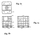
- the outer support structure 30 is arranged to enclose and support the side walls of the inner container. As can be seen in Figs. 1b and 1c, the support structure encompasses the entire inner container at its side walls and is formed of a grid of first and second elongate elements 1, 2. The elements are connected to one another at intersections 9. The upper and lower ends of the vertical elements 2 are connected to rim elements 40, 50 which also circumvent the container. In the embodiment of Fig. 1b, the lower rim element 50 is interrupted at the point of the discharge opening 14.
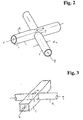
- Embodiments of the intersections 9 are shown in Figs. 2 and 3.
- An opening 3 is formed in the first element 1 so as to allow the second element 2 to penetrate therethrough.
- the first element is a tubular member which may be circular in cross-section (Fig. 2) or rectangular (Fig. 3).
- the second element is also tubular and has a diameter d2 which is naturally smaller than the diameter d1 of the first tube.
- the outer diameter d2 of the second element is 20% to 30% smaller than the outer diameter d1 of the first element.
- the diameter of the first tube 1 can be about 22 mm with the diameter of the second tube 2 being 16 mm.
- both the first and second elements could be solid bars, it is preferred that both of the elements be tubular in construction. It is also possible that the first element be an open profile, which will be discussed below.
- the cross-sectional profile of the tubes need not be circular and square as shown in Figs. 2 and 3, but could also be generally oval, square, triangular or even combinations of the above forms.
- the first and second elements 1, 2 are connected to one another at one or more positions in the region of their intersection.
- two connecting positions 4 are located at the outer surface of the second element 2 which lies opposed to the inner surface of the first element 1 (only the top position 4 is shown).
- the elements 1, 2 are metal tubes
- the second tube when properly positioned within the first tube is welded at the positions 4 under sufficient pressure to urge the two sides of the first tube 1 into contact with the outer wall of the second tube 2 under formation of the weld.
- the second tube 2 requires no further processing once purchased from the manufacturer.
- the first tube need only be provided with the receiving hole 3 at the proper orientation and spacing to the form the grid support structure.
- the inner dimension of the receiving opening 3 formed in the first element 1 is preferably sized with respect to the outer dimension d2 of the second element 2 such that there is no play between the receiving opening 3 and the second element 2.
- the second element 2 is then inserted through the opening 3 under the application of force to overcome friction between the outer surface of the second element 2 and the inner defining surfaces of the receiving opening 3. In this manner a non-positive frictional fit is established between the first and second elements 1, 2.
- This construction adds to the mechanical strength of the connection assembly, particularly against bending moments which may arise under load in the plane of the two elements.
- the above described procedure is preferred, however, a frictional fit or form fit of various types may also be used.
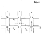
- Fig. 4 shows an arrangement of the grid structure in which the first elements 1 are arranged vertically and the second elements 2 are arranged horizontally and penetrate the first vertical elements 1. Although this orientation is preferred, it is also possible to provide the first element 1 in the horizontal position with the second vertical elements penetrating therethrough in horizontal direction as shown in Figs. 1b and 1c.
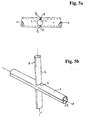
- the exterior ridges 8 of the second element 2 penetrate the opening 3 as in Fig. 5a.
- the interior of the first element 1 is provided with two inner ridges 5 which oppose one another about the centre axis x.
- the crest of the exterior ridges 8 at the intersection are dimensioned to engage with the crest of the inner ridges 5 to form the connection positions.
- the second tubular elements 2 define tangential planes 10, 20, which also define the tangential inner and outer planes of the grid support structure.
- the contact positions P 1 , P 2 of the ridges with the second element 2 lie at the two tangential planes 10, 20.
- the maximum width of the intersection corresponds to the distance W and represents the effective dimension of the first tube 1 in the z direction.
- the overall width W is only slightly larger than the distance between the tangential planes 10, 20 of the smaller diameter tube 2. This is particularly advantageous for the pallet container in terms of space savings.
- all surfaces at the intersection are smooth or rounded without any projecting edges. This avoids "catching" of two pallet containers during handling, for example when the containers are placed adjacent to one another.
- the intersection for the grid support structure of the present invention can also be constructed as shown in Figs. 8 or 9.
- the first tubular element 1 is provided with three ridges 5 formed in its interior.
- the second element 2 penetrates the receiving opening 3 so as to contact only one of the three inner ridges 5.
- the two elements 1, 2 are connected to one another at only one position, indicated with the reference numeral 4.
- the centre axis y of the smaller diameter element 2 does not intersect the centre axis x of the first tubular element 1.
- the number of ridges contacted by the second tubular element 2 will depend on its diameter and the orientation of the receiving hole for penetration.
- Fig. 8 the number of ridges contacted by the second tubular element 2 will depend on its diameter and the orientation of the receiving hole for penetration.
- the grid support structure 30 comprises an upper rim 40 and a lower rim 50 to which the vertical elements of the grid are connected in a T-intersection.
- the vertical elements can be the first element 1 having the hole 3 for penetration or can also be the second element 2.
- Figs. 12 and 13 show arrangements for connecting the vertical elements to the upper rim element 40. The same type of T-intersection can of course be used for the lower rim element 50.
- the basic principles for forming the T-intersection are the same as those described above for the crossing intersection of the first and second elements.
- the rim element 40 will be of larger dimension and correspond to the first elongate element described above.
- the vertical element indicated by way of example in Fig. 1 with the reference numeral 1, will correspond to the second element described above in the crossing intersections.
- the receiving hole 42 as shown in Fig. 12 is formed such that the vertical element 1 does not penetrate through the rim element 40.
- the opening is already provided by the open side of the U-shaped profile 40 as the rim element.
- the provisions for connecting the two elements as well as the possible forms and shapes of the respective elements are the same as in the crossing intersection described above in conjunction with the Figs. 2 to 11.
- Figs. 12 and 13 show particularly suitable T-connections in which the rim element 40 comprises two inner ridges which contact the vertical element 1 once inserted into the rim element 40.
- the various elements 1, 2, 40, 50 be made of metal tubes and be welded at their connection positions, it is also contemplated that the connections be made by means of a form fit produced by deformation of the respective elements.
- a recess or indentation could be formed with a press into the outer tube 1 at the intersection location 4. The recess would be deep enough to form a matching recess in the outer surface of the inner second element, whereby a form fit interconnection results.
- the second tube 2 could be deformed either on the interior of the receiving hole 3 or outside of it.
- the second tube 2 could be provided with indentations which match the position of the inner ridges of the first tube 1. Engagement of the ridges in the indentations would produce a fit which would prevent axial movement of the second tube with respect to the first tube.
Landscapes
- Engineering & Computer Science (AREA)
- Mechanical Engineering (AREA)
- Pallets (AREA)
- Packaging Of Annular Or Rod-Shaped Articles, Wearing Apparel, Cassettes, Or The Like (AREA)
Claims (23)
- Palettenbehälter mit:einem inneren Kunststoffbehälter (10) zum Transport von Flüssigkeiten, wobei die Bodenwandung des inneren Behälters (10) von einer Palette (20) oder einer palettenartigen Struktur getragen ist,einer Trägerstruktur (30), die angeordnet ist, um die Seitenwände des inneren Behälters (10) einzuschliessen und zu berühren, und die als Gitter aus ersten und zweiten länglichen Elementen (1, 2) ausgebildet ist, die an ihren Schnittpunkten (9) miteinander verbunden sind,bei dem jedes erste längliche Element (1) eine Aufnahmeöffnung (3) hat, durch welche das entsprechende zweite längliche Element (2) geführt ist, wobei die ersten und zweiten länglichen Elemente (1, 2) an einer oder mehreren Position/en (P1, P2) im Bereich ihrer Schnittstelle (9) miteinander verbunden sind.
- Baugruppe nach Anspruch 1, bei der ein Innenmass der Aufnahmeöffnung (3) des ersten Elements (1) gegenüber dem Aussenmass (d2) des zweiten Elements (2) so dimensioniert ist, dass ein Reibschluss zwischen den beiden Elementen (1, 2) hergestellt ist.
- Behälter nach Anspruch 1 oder 2, bei dem die Verbindungspositionen (P1, P2) in zwei tangentialen Ebenen (10, 20) des Gitters ausgebildet sind, die durch äussere Flächen der zweiten Elemente (2) definiert sind.
- Behälter nach Anspruch 1, 2 oder 3, bei dem zwei Verbindungen an den Positionen (P1, P2) ausgebildet sind, wo die Aussenfläche des zweiten Elements (2) der Innenfläche des ersten Elements (1) gegenüber liegt.
- Behälter nach einem der Ansprüche 1 bis 4, bei dem die ersten und zweiten Elemente (1, 2) rohrförmig sind, wobei die ersten und zweiten Elemente im Querschnitt allgemein rund, oval, quadratisch, dreieckig oder rechteckig sind.
- Behälter nach Anspruch 3, 4 oder 5, bei dem die Aussenfläche des zweiten Elements (2) mit zwei Stegen (8) versehen sind, die die Innenfläche des ersten Elements (1) zur Ausbildung der beiden Verbindungspositionen (P1, P2) berühren.
- Behälter nach Anspruch 1 oder 2, bei dem das erste längliche Element (1) rohrförmig ist und einen oder mehrere Innensteg/e (5) umfasst, wobei die Stege (5) so angeordnet sind, dass sie die Aussenfläche des zweiten Elements (2) zur Ausbildung der einen oderer mehreren Position/en (P1, P2) berühren, an der/denen die Elemente (1, 2) verbunden sind.
- Behälter nach Anspruch 7, bei dem die ersten und zweiten Elemente (1, 2) im Querschnitt rohrförmig und rund sind, wobei das erste Element (1) zwei Innenstege (5) umfasst, die bezüglich ihrer Mittelachse (x) einander gegenüber liegend ausgebildet sind, wobei die beiden Stege (5) die Aussenfläche des zweiten rohrförmigen Elements (2) berühren zur Ausbildung der beiden Positionen (P1, P2), an denen die Elemente (1, 2) verbunden sind.
- Behälter nach Anspruch 7, bei dem das erste Element (1) drei Innenstege (5) umfasst, wobei die Aufnahmeöffnung (3) so vorgesehen ist, dass die Aussenfläche des zweiten Elements (2) einen der Innenstege (5) an der Position berührt, an der die Elemente (1, 2) verbunden sind.
- Behälter nach Anspruch 7, bei dem das erste Element (1) vier Innenstege (a, b, c, d) umfasst, wobei die vier Stege so angeordnet sind, dass sie die Aussenfläche des zweiten Elements an vier Positionen (a, b, c, d) berühren, an denen die Elemente (1, 2) verbunden sind.
- Behälter nach einem der Ansprüche 7 bis 10, bei dem die ersten und zweiten länglichen Elemente (1, 2) rohrförmig sind, wobei die Elemente (1, 2) im Querschnitt allgemein rund, oval, quadratisch, dreieckig oder rechteckig sind.
- Behälter nach Anspruch 1 oder 2, bei dem das erste längliche Element (1) als offenes Profil ausgebildet ist, zum Beispiel als U- oder C-förmiges Profil, wobei das Profil (1) einen oder mehrere Innensteg/e (5) umfasst, die so angeordnet sind, dass sie die Aussenfläche des zweiten Elements zur Ausbildung der einen oder mehreren Position/en (P3) berühren, an der/denen die Elemente (1, 2) verbunden sind.
- Behälter nach Anspruch 12, bei dem das zweite längliche Element (2) rohrförmig ist, wobei sein Querschnitt allgemein rund, oval, quadratisch, dreieckig oder rechteckig ist.
- Behälter nach einem der Ansprüche 1, 2, 7 oder 12, bei dem das zweite längliche Element (2) eine Platte (2a) ist, die einen Schlitz (3a) als Aufnahmeöffnung in dem ersten länglichen Element (1) durchquert.
- Behälter nach Anspruch 14, bei dem das erste längliche Element (1) ein Rohr (1) mit mindestens einem Innensteg (5) umfassst, wobei die Platte (21) einen weiteren Steg (5a) umfasst, der zur Berührung mit dem Innensteg von Rohr (1) ausgelegt ist, wenn sie in die Aufnahmeöffnung (3) eingeschoben ist, um die Position bereit zu stellen, an der die beiden Elemente (1, 2) verbunden sind.
- Behälter nach einem der Ansprüche 1 bis 15, bei dem die ersten und zweiten länglichen Elemente (1, 2) Metallrohre sind und durch Schweissen an der einen oder den mehreren Positionen (P1, P2) verbunden sind.
- Behälter nach einem der Ansprüche 1 bis 15, bei dem die ersten und zweiten länglichen Elemente (1, 2) aus einem Kunststoff bestehen und die Elemente (1, 2) an dieser einen oder diesen mehreren Positionen (P1, P2) durch einen Kleber oder durch Heissverklebung verbunden sind.
- Behälter nach einem der Ansprüche 1 bis 15, bei dem die ersten und zweiten länglichen Elemente (1, 2) an dieser einen oder diesen mehreren Positionen (P1, P2, P3) durch Verformen eines Elements oder beider Elemente (1, 2) an einer oder mehreren dieser Positionen (P1, P2, P3) verbunden sind, um einen Formschluss zwischen den beiden Elementen (1, 2) herzustellen.
- Behälter nach einem der Ansprüche 1 bis 18, bei dem die ersten länglichen Elemente (1) der Gitterträgerstruktur (30) vertikal angeordnet sind, und die zweiten länglichen Elemente (2) horizontal angeordnet sind, oder umgekehrt, die ersten länglichen Elemente (1) horizontal und die zweiten länglichen Elemente (2) vertikal angeordnet sind.
- Behälter nach Anspruch 19, bei dem die vertikalen Elemente (1, 2) an ihren oberen und unteren Enden mit den oberen bzw. unteren Randelementen (40, 50) T-Schnittstellen ausbilden, wobei sich die Randelemente (40, 50) um den Umfang der Trägerstruktur (30) erstrecken.
- Behälter nach Anspruch 20, bei dem jede T-Schnittstelle ausgebildet ist, indem das vertikale Element (1, 2) in eine Öffnung (42) des Randelements (40, 50) eingeführt ist, aber nicht durch das Randelement (40, 50) hindurch geht.
- Behälter nach Anspruch 21, bei dem das vertikale Element (1, 2) und das Randelement (40, 50) an einer oder mehreren Positionen im Bereich der T-Schnittstelle miteinander verbunden sind.
- Behälter nach Anspruch 22, bei dem das Randelement ein geschlossenes Rohrprofil oder ein z.B. U-förmiges oder C-förmiges offenes Profil hat und einen oder mehrere darin ausgebildete/n Innensteg/e (80) aufweist, wobei die Innenstege (80) so angeordnet sind, dass sie die Aussenfläche des vertikalen Elements (1, 2) berühren, wenn sie in das Randelement (40,50) eingeführt sind.
Priority Applications (7)
| Application Number | Priority Date | Filing Date | Title |
|---|---|---|---|
| ES97119264T ES2167665T3 (es) | 1997-11-04 | 1997-11-04 | Contenedor tipo palet con estructura de soporte en forma de rejilla. |
| PT97119264T PT916592E (pt) | 1997-11-04 | 1997-11-04 | Contentor de paletes com estrutura de suporte em grade |
| AT97119264T ATE206380T1 (de) | 1997-11-04 | 1997-11-04 | Palettenbehälter mit gittertragstruktur |
| EP97119264A EP0916592B1 (de) | 1997-11-04 | 1997-11-04 | Palettenbehälter mit Gittertragstruktur |
| DK97119264T DK0916592T3 (da) | 1997-11-04 | 1997-11-04 | Pallecontainer med gitterbærestruktur |
| DE69707135T DE69707135T2 (de) | 1997-11-04 | 1997-11-04 | Palettenbehälter mit Gittertragstruktur |
| US09/471,514 US6290082B1 (en) | 1997-11-04 | 1999-12-23 | Pallet container with grid support structure |
Applications Claiming Priority (2)
| Application Number | Priority Date | Filing Date | Title |
|---|---|---|---|
| EP97119264A EP0916592B1 (de) | 1997-11-04 | 1997-11-04 | Palettenbehälter mit Gittertragstruktur |
| US09/471,514 US6290082B1 (en) | 1997-11-04 | 1999-12-23 | Pallet container with grid support structure |
Publications (2)
| Publication Number | Publication Date |
|---|---|
| EP0916592A1 EP0916592A1 (de) | 1999-05-19 |
| EP0916592B1 true EP0916592B1 (de) | 2001-10-04 |
Family
ID=26145871
Family Applications (1)
| Application Number | Title | Priority Date | Filing Date |
|---|---|---|---|
| EP97119264A Expired - Lifetime EP0916592B1 (de) | 1997-11-04 | 1997-11-04 | Palettenbehälter mit Gittertragstruktur |
Country Status (7)
| Country | Link |
|---|---|
| US (1) | US6290082B1 (de) |
| EP (1) | EP0916592B1 (de) |
| AT (1) | ATE206380T1 (de) |
| DE (1) | DE69707135T2 (de) |
| DK (1) | DK0916592T3 (de) |
| ES (1) | ES2167665T3 (de) |
| PT (1) | PT916592E (de) |
Families Citing this family (15)
| Publication number | Priority date | Publication date | Assignee | Title |
|---|---|---|---|---|
| DK0916592T3 (da) | 1997-11-04 | 2002-01-28 | Royal Packaging Industry Van L | Pallecontainer med gitterbærestruktur |
| US6758360B2 (en) | 1999-12-23 | 2004-07-06 | Royal Packaging Industry Leer N.V. | Pallet container with grid support structure |
| DE10103656A1 (de) * | 2000-05-25 | 2001-12-06 | Mauser Werke Gmbh & Co Kg | Palettencontainer |
| US6722291B2 (en) | 2002-03-19 | 2004-04-20 | Slooters, Inc. | Separation members for selective placement between sheet members oriented horizontally and stacked vertically and method of usage thereof |
| NL1020438C2 (nl) * | 2002-04-19 | 2003-10-21 | Leer Koninklijke Emballage | IBC voor brandbare produkten. |
| DE20216058U1 (de) * | 2002-10-18 | 2003-02-06 | Richter, Günter, 57610 Altenkirchen | Behälter mit einem Innenbehälter und einem gitterförmigen äußeren Mantelkörper |
| DE10301517B3 (de) * | 2003-01-17 | 2004-03-11 | Protechna S.A. | Transport- und Lagerbehälter für Flüssigkeiten |
| US20040177589A1 (en) * | 2003-03-14 | 2004-09-16 | United Integrated Services Co., Ltd. | Raised floor panel fabrication method |
| DE502004000779D1 (de) | 2003-04-25 | 2006-07-27 | Mauser Werke Gmbh & Co Kg | Palettencontainer |
| US7399942B2 (en) * | 2006-01-06 | 2008-07-15 | Gm Global Technology Operations, Inc. | Method for projection bonding of telescoped tubes |
| DE202012001726U1 (de) * | 2012-02-20 | 2012-06-14 | Dietmar Przytulla | Palettenbehälter |
| ES2611227T3 (es) * | 2012-09-21 | 2017-05-05 | Mauser-Werke Gmbh | Contenedor de plataformas de carga |
| FR3037319A1 (fr) * | 2015-06-12 | 2016-12-16 | Sotralentz Packaging | Conteneur a palette empilable muni d'une armature superieure de renfort |
| DE102017006653B4 (de) * | 2017-07-13 | 2023-10-26 | Mauser-Werke Gmbh | Palettencontainer |
| IT201700095075A1 (it) * | 2017-08-22 | 2019-02-22 | Maschio N S S R L | Gabbia metallica per cisterne. |
Family Cites Families (12)
| Publication number | Priority date | Publication date | Assignee | Title |
|---|---|---|---|---|
| GB1051857A (de) * | ||||
| SE319454B (de) * | 1967-08-23 | 1970-01-19 | S Dubois | |
| GB2106948A (en) | 1981-09-22 | 1983-04-20 | Brian Harmer | Metal floor-grating |
| GB2133430A (en) | 1982-12-24 | 1984-07-25 | John Raymond Williams | Metallic structure |
| DE3344351C2 (de) | 1983-12-08 | 1987-01-08 | Allendorfer Fabrik für Stahlverarbeitung Ing. Herbert Panne GmbH & Co KG, 6349 Greifenstein | Gitterrost |
| US4676373A (en) * | 1984-11-20 | 1987-06-30 | Helmhold Schneider | Plastic pallet container |
| DE3819911A1 (de) * | 1988-06-11 | 1989-12-14 | Schuetz Werke Gmbh Co Kg | Palettenbehaelter |
| US4909387A (en) * | 1988-11-24 | 1990-03-20 | Schuetz Udo | Pallet container with an exchangeable inner container of a synthetic resin and an outer jacket of metal lattice bars |
| DK168243B1 (da) | 1989-08-14 | 1994-02-28 | Fiberline As | Profilsamling |
| DE19511723C1 (de) * | 1995-03-30 | 1996-08-29 | Protechna Sa | Palettenbehälter |
| GB9515460D0 (en) | 1995-07-27 | 1995-09-27 | Mita Uk Ltd | Structural support system and method for its manufacture pultruded grp grating |
| DK0916592T3 (da) | 1997-11-04 | 2002-01-28 | Royal Packaging Industry Van L | Pallecontainer med gitterbærestruktur |
-
1997
- 1997-11-04 DK DK97119264T patent/DK0916592T3/da active
- 1997-11-04 DE DE69707135T patent/DE69707135T2/de not_active Expired - Lifetime
- 1997-11-04 AT AT97119264T patent/ATE206380T1/de active
- 1997-11-04 EP EP97119264A patent/EP0916592B1/de not_active Expired - Lifetime
- 1997-11-04 PT PT97119264T patent/PT916592E/pt unknown
- 1997-11-04 ES ES97119264T patent/ES2167665T3/es not_active Expired - Lifetime
-
1999
- 1999-12-23 US US09/471,514 patent/US6290082B1/en not_active Expired - Lifetime
Also Published As
| Publication number | Publication date |
|---|---|
| DE69707135D1 (de) | 2001-11-08 |
| US6290082B1 (en) | 2001-09-18 |
| EP0916592A1 (de) | 1999-05-19 |
| PT916592E (pt) | 2002-03-28 |
| DE69707135T2 (de) | 2002-06-20 |
| ATE206380T1 (de) | 2001-10-15 |
| DK0916592T3 (da) | 2002-01-28 |
| ES2167665T3 (es) | 2002-05-16 |
Similar Documents
| Publication | Publication Date | Title |
|---|---|---|
| US6758360B2 (en) | Pallet container with grid support structure | |
| EP0916592B1 (de) | Palettenbehälter mit Gittertragstruktur | |
| RU2104238C1 (ru) | Емкость с поддоном для транспортировки и хранения жидкостей | |
| CA2174920C (en) | Modular spill deck | |
| KR101526302B1 (ko) | 팔레트 컨테이너 | |
| US20080257230A1 (en) | Pallet container | |
| US20020127053A1 (en) | Connection assembly | |
| US5738240A (en) | Composite shipping container with tubular member pallet | |
| JP2001341741A (ja) | パレットコンテナ | |
| JP2779232B2 (ja) | 液体及び細かく分散したばら積み材料を運搬及び/又は貯蔵する容器 | |
| CA2409852C (en) | Pallet container | |
| CN100448760C (zh) | 液体储运容器 | |
| JP7637792B2 (ja) | 支持ユニット及びパレット | |
| US4966293A (en) | Transport and/or storage container for liquids and finely divided bulk solids | |
| CN104245534B (zh) | 托板容器 | |
| JP7382051B2 (ja) | パレット | |
| KR20030070018A (ko) | 팔레트 컨테이너 | |
| JP7174075B2 (ja) | 液体の輸送及び貯蔵容器 | |
| JP4808899B2 (ja) | パレットコンテナ | |
| JPH10139041A (ja) | パレット | |
| EP1457617A1 (de) | Eine Verbindungsanordnung für eine Gitterstruktur | |
| RU2205778C2 (ru) | Сборный поддон | |
| KR200322754Y1 (ko) | 종이 파레트 | |
| JP2000053133A (ja) | 平らな荷受け用パレット |
Legal Events
| Date | Code | Title | Description |
|---|---|---|---|
| PUAI | Public reference made under article 153(3) epc to a published international application that has entered the european phase |
Free format text: ORIGINAL CODE: 0009012 |
|
| AK | Designated contracting states |
Kind code of ref document: A1 Designated state(s): AT BE CH DE DK ES FI FR GB GR IE IT LI LU MC NL PT SE |
|
| AX | Request for extension of the european patent |
Free format text: AL;LT;LV;MK;RO;SI |
|
| 17P | Request for examination filed |
Effective date: 19991119 |
|
| AKX | Designation fees paid |
Free format text: AT BE CH DE DK ES FI FR GB GR IE IT LI LU MC NL PT SE |
|
| RAP1 | Party data changed (applicant data changed or rights of an application transferred) |
Owner name: ROYAL PACKAGING INDUSTRY VAN LEER N.V. |
|
| GRAG | Despatch of communication of intention to grant |
Free format text: ORIGINAL CODE: EPIDOS AGRA |
|
| 17Q | First examination report despatched |
Effective date: 20001006 |
|
| GRAG | Despatch of communication of intention to grant |
Free format text: ORIGINAL CODE: EPIDOS AGRA |
|
| GRAH | Despatch of communication of intention to grant a patent |
Free format text: ORIGINAL CODE: EPIDOS IGRA |
|
| GRAH | Despatch of communication of intention to grant a patent |
Free format text: ORIGINAL CODE: EPIDOS IGRA |
|
| GRAA | (expected) grant |
Free format text: ORIGINAL CODE: 0009210 |
|
| AK | Designated contracting states |
Kind code of ref document: B1 Designated state(s): AT BE CH DE DK ES FI FR GB GR IE IT LI LU MC NL PT SE |
|
| PG25 | Lapsed in a contracting state [announced via postgrant information from national office to epo] |
Ref country code: LI Free format text: LAPSE BECAUSE OF FAILURE TO SUBMIT A TRANSLATION OF THE DESCRIPTION OR TO PAY THE FEE WITHIN THE PRESCRIBED TIME-LIMIT Effective date: 20011004 Ref country code: CH Free format text: LAPSE BECAUSE OF FAILURE TO SUBMIT A TRANSLATION OF THE DESCRIPTION OR TO PAY THE FEE WITHIN THE PRESCRIBED TIME-LIMIT Effective date: 20011004 |
|
| REF | Corresponds to: |
Ref document number: 206380 Country of ref document: AT Date of ref document: 20011015 Kind code of ref document: T |
|
| REG | Reference to a national code |
Ref country code: CH Ref legal event code: EP |
|
| PG25 | Lapsed in a contracting state [announced via postgrant information from national office to epo] |
Ref country code: MC Free format text: LAPSE BECAUSE OF NON-PAYMENT OF DUE FEES Effective date: 20011104 Ref country code: LU Free format text: LAPSE BECAUSE OF NON-PAYMENT OF DUE FEES Effective date: 20011104 |
|
| PG25 | Lapsed in a contracting state [announced via postgrant information from national office to epo] |
Ref country code: IE Free format text: LAPSE BECAUSE OF FAILURE TO SUBMIT A TRANSLATION OF THE DESCRIPTION OR TO PAY THE FEE WITHIN THE PRESCRIBED TIME-LIMIT Effective date: 20011105 |
|
| REF | Corresponds to: |
Ref document number: 69707135 Country of ref document: DE Date of ref document: 20011108 |
|
| REG | Reference to a national code |
Ref country code: IE Ref legal event code: FG4D |
|
| REG | Reference to a national code |
Ref country code: GB Ref legal event code: IF02 |
|
| REG | Reference to a national code |
Ref country code: DK Ref legal event code: T3 |
|
| ET | Fr: translation filed | ||
| REG | Reference to a national code |
Ref country code: PT Ref legal event code: SC4A Free format text: AVAILABILITY OF NATIONAL TRANSLATION Effective date: 20020103 |
|
| REG | Reference to a national code |
Ref country code: CH Ref legal event code: PL |
|
| REG | Reference to a national code |
Ref country code: ES Ref legal event code: FG2A Ref document number: 2167665 Country of ref document: ES Kind code of ref document: T3 |
|
| REG | Reference to a national code |
Ref country code: GR Ref legal event code: EP Ref document number: 20020400011 Country of ref document: GR |
|
| PLBE | No opposition filed within time limit |
Free format text: ORIGINAL CODE: 0009261 |
|
| STAA | Information on the status of an ep patent application or granted ep patent |
Free format text: STATUS: NO OPPOSITION FILED WITHIN TIME LIMIT |
|
| REG | Reference to a national code |
Ref country code: IE Ref legal event code: MM4A |
|
| 26N | No opposition filed | ||
| PGFP | Annual fee paid to national office [announced via postgrant information from national office to epo] |
Ref country code: DK Payment date: 20081119 Year of fee payment: 12 |
|
| PGFP | Annual fee paid to national office [announced via postgrant information from national office to epo] |
Ref country code: PT Payment date: 20081024 Year of fee payment: 12 Ref country code: FI Payment date: 20081126 Year of fee payment: 12 |
|
| PGFP | Annual fee paid to national office [announced via postgrant information from national office to epo] |
Ref country code: SE Payment date: 20081105 Year of fee payment: 12 |
|
| PGFP | Annual fee paid to national office [announced via postgrant information from national office to epo] |
Ref country code: GR Payment date: 20081127 Year of fee payment: 12 |
|
| REG | Reference to a national code |
Ref country code: PT Ref legal event code: MM4A Free format text: LAPSE DUE TO NON-PAYMENT OF FEES Effective date: 20100504 |
|
| EUG | Se: european patent has lapsed | ||
| REG | Reference to a national code |
Ref country code: DK Ref legal event code: EBP |
|
| PG25 | Lapsed in a contracting state [announced via postgrant information from national office to epo] |
Ref country code: PT Free format text: LAPSE BECAUSE OF NON-PAYMENT OF DUE FEES Effective date: 20100504 |
|
| PG25 | Lapsed in a contracting state [announced via postgrant information from national office to epo] |
Ref country code: FI Free format text: LAPSE BECAUSE OF NON-PAYMENT OF DUE FEES Effective date: 20091104 |
|
| PG25 | Lapsed in a contracting state [announced via postgrant information from national office to epo] |
Ref country code: GR Free format text: LAPSE BECAUSE OF NON-PAYMENT OF DUE FEES Effective date: 20100602 |
|
| PG25 | Lapsed in a contracting state [announced via postgrant information from national office to epo] |
Ref country code: DK Free format text: LAPSE BECAUSE OF NON-PAYMENT OF DUE FEES Effective date: 20091130 |
|
| PG25 | Lapsed in a contracting state [announced via postgrant information from national office to epo] |
Ref country code: SE Free format text: LAPSE BECAUSE OF NON-PAYMENT OF DUE FEES Effective date: 20091105 |
|
| PGFP | Annual fee paid to national office [announced via postgrant information from national office to epo] |
Ref country code: AT Payment date: 20131127 Year of fee payment: 17 Ref country code: GB Payment date: 20131202 Year of fee payment: 17 |
|
| PGFP | Annual fee paid to national office [announced via postgrant information from national office to epo] |
Ref country code: NL Payment date: 20131127 Year of fee payment: 17 Ref country code: FR Payment date: 20131129 Year of fee payment: 17 Ref country code: IT Payment date: 20131126 Year of fee payment: 17 Ref country code: ES Payment date: 20131220 Year of fee payment: 17 |
|
| PGFP | Annual fee paid to national office [announced via postgrant information from national office to epo] |
Ref country code: BE Payment date: 20131223 Year of fee payment: 17 |
|
| PGFP | Annual fee paid to national office [announced via postgrant information from national office to epo] |
Ref country code: DE Payment date: 20140130 Year of fee payment: 17 |
|
| REG | Reference to a national code |
Ref country code: DE Ref legal event code: R119 Ref document number: 69707135 Country of ref document: DE |
|
| REG | Reference to a national code |
Ref country code: NL Ref legal event code: V1 Effective date: 20150601 |
|
| PG25 | Lapsed in a contracting state [announced via postgrant information from national office to epo] |
Ref country code: BE Free format text: LAPSE BECAUSE OF NON-PAYMENT OF DUE FEES Effective date: 20141130 |
|
| REG | Reference to a national code |
Ref country code: AT Ref legal event code: MM01 Ref document number: 206380 Country of ref document: AT Kind code of ref document: T Effective date: 20141104 |
|
| GBPC | Gb: european patent ceased through non-payment of renewal fee |
Effective date: 20141104 |
|
| REG | Reference to a national code |
Ref country code: FR Ref legal event code: ST Effective date: 20150731 |
|
| PG25 | Lapsed in a contracting state [announced via postgrant information from national office to epo] |
Ref country code: NL Free format text: LAPSE BECAUSE OF NON-PAYMENT OF DUE FEES Effective date: 20150601 Ref country code: AT Free format text: LAPSE BECAUSE OF NON-PAYMENT OF DUE FEES Effective date: 20141104 |
|
| PG25 | Lapsed in a contracting state [announced via postgrant information from national office to epo] |
Ref country code: GB Free format text: LAPSE BECAUSE OF NON-PAYMENT OF DUE FEES Effective date: 20141104 Ref country code: DE Free format text: LAPSE BECAUSE OF NON-PAYMENT OF DUE FEES Effective date: 20150602 |
|
| PG25 | Lapsed in a contracting state [announced via postgrant information from national office to epo] |
Ref country code: FR Free format text: LAPSE BECAUSE OF NON-PAYMENT OF DUE FEES Effective date: 20141201 |
|
| REG | Reference to a national code |
Ref country code: ES Ref legal event code: FD2A Effective date: 20151229 |
|
| PG25 | Lapsed in a contracting state [announced via postgrant information from national office to epo] |
Ref country code: IT Free format text: LAPSE BECAUSE OF NON-PAYMENT OF DUE FEES Effective date: 20141104 |
|
| PG25 | Lapsed in a contracting state [announced via postgrant information from national office to epo] |
Ref country code: ES Free format text: LAPSE BECAUSE OF NON-PAYMENT OF DUE FEES Effective date: 20141105 |