EP0916596A1 - Régulateur de débit pour un récipient d'aérosol pressurisé - Google Patents
Régulateur de débit pour un récipient d'aérosol pressurisé Download PDFInfo
- Publication number
- EP0916596A1 EP0916596A1 EP98103763A EP98103763A EP0916596A1 EP 0916596 A1 EP0916596 A1 EP 0916596A1 EP 98103763 A EP98103763 A EP 98103763A EP 98103763 A EP98103763 A EP 98103763A EP 0916596 A1 EP0916596 A1 EP 0916596A1
- Authority
- EP
- European Patent Office
- Prior art keywords
- round surface
- aerosol
- controlling sleeve
- housing
- outer round
- Prior art date
- Legal status (The legal status is an assumption and is not a legal conclusion. Google has not performed a legal analysis and makes no representation as to the accuracy of the status listed.)
- Granted
Links
- 239000000443 aerosol Substances 0.000 title claims abstract description 166
- 238000003780 insertion Methods 0.000 claims abstract description 64
- 230000037431 insertion Effects 0.000 claims abstract description 64
- 238000004891 communication Methods 0.000 claims abstract description 23
- 238000005507 spraying Methods 0.000 claims abstract description 22
- 239000007921 spray Substances 0.000 abstract description 26
- 238000009877 rendering Methods 0.000 abstract description 7
- 230000001276 controlling effect Effects 0.000 description 64
- 239000007789 gas Substances 0.000 description 21
- 239000003380 propellant Substances 0.000 description 19
- BVKZGUZCCUSVTD-UHFFFAOYSA-L Carbonate Chemical compound [O-]C([O-])=O BVKZGUZCCUSVTD-UHFFFAOYSA-L 0.000 description 13
- 239000002917 insecticide Substances 0.000 description 12
- IJGRMHOSHXDMSA-UHFFFAOYSA-N Atomic nitrogen Chemical compound N#N IJGRMHOSHXDMSA-UHFFFAOYSA-N 0.000 description 10
- LFQSCWFLJHTTHZ-UHFFFAOYSA-N Ethanol Chemical compound CCO LFQSCWFLJHTTHZ-UHFFFAOYSA-N 0.000 description 10
- 239000003795 chemical substances by application Substances 0.000 description 10
- 230000006835 compression Effects 0.000 description 10
- 238000007906 compression Methods 0.000 description 10
- 239000011928 denatured alcohol Substances 0.000 description 10
- 239000002781 deodorant agent Substances 0.000 description 10
- 239000002304 perfume Substances 0.000 description 8
- 238000011282 treatment Methods 0.000 description 8
- -1 Polyoxyethylene Polymers 0.000 description 7
- PEDCQBHIVMGVHV-UHFFFAOYSA-N Glycerine Chemical compound OCC(O)CO PEDCQBHIVMGVHV-UHFFFAOYSA-N 0.000 description 6
- 229920003171 Poly (ethylene oxide) Polymers 0.000 description 5
- 229910052757 nitrogen Inorganic materials 0.000 description 5
- XLYOFNOQVPJJNP-UHFFFAOYSA-N water Substances O XLYOFNOQVPJJNP-UHFFFAOYSA-N 0.000 description 5
- ZAKOWWREFLAJOT-CEFNRUSXSA-N D-alpha-tocopherylacetate Chemical compound CC(=O)OC1=C(C)C(C)=C2O[C@@](CCC[C@H](C)CCC[C@H](C)CCCC(C)C)(C)CCC2=C1C ZAKOWWREFLAJOT-CEFNRUSXSA-N 0.000 description 4
- 230000001166 anti-perspirative effect Effects 0.000 description 4
- 239000003213 antiperspirant Substances 0.000 description 4
- 239000002537 cosmetic Substances 0.000 description 4
- 239000003676 hair preparation Substances 0.000 description 4
- 229940042585 tocopherol acetate Drugs 0.000 description 4
- NOOLISFMXDJSKH-KXUCPTDWSA-N (-)-Menthol Chemical compound CC(C)[C@@H]1CC[C@@H](C)C[C@H]1O NOOLISFMXDJSKH-KXUCPTDWSA-N 0.000 description 3
- 241001674044 Blattodea Species 0.000 description 3
- KFZMGEQAYNKOFK-UHFFFAOYSA-N Isopropanol Chemical compound CC(C)O KFZMGEQAYNKOFK-UHFFFAOYSA-N 0.000 description 3
- DNIAPMSPPWPWGF-UHFFFAOYSA-N Propylene glycol Chemical compound CC(O)CO DNIAPMSPPWPWGF-UHFFFAOYSA-N 0.000 description 3
- 230000001741 anti-phlogistic effect Effects 0.000 description 3
- 230000007423 decrease Effects 0.000 description 3
- 238000010413 gardening Methods 0.000 description 3
- 239000000077 insect repellent Substances 0.000 description 3
- 239000007788 liquid Substances 0.000 description 3
- 238000004519 manufacturing process Methods 0.000 description 3
- 230000003387 muscular Effects 0.000 description 3
- 239000008257 shaving cream Substances 0.000 description 3
- 230000000475 sunscreen effect Effects 0.000 description 3
- 239000000516 sunscreening agent Substances 0.000 description 3
- 235000015961 tonic Nutrition 0.000 description 3
- 230000001256 tonic effect Effects 0.000 description 3
- 238000004078 waterproofing Methods 0.000 description 3
- SVTBMSDMJJWYQN-UHFFFAOYSA-N 2-methylpentane-2,4-diol Chemical compound CC(O)CC(C)(C)O SVTBMSDMJJWYQN-UHFFFAOYSA-N 0.000 description 2
- LYCAIKOWRPUZTN-UHFFFAOYSA-N Ethylene glycol Chemical compound OCCO LYCAIKOWRPUZTN-UHFFFAOYSA-N 0.000 description 2
- 239000004354 Hydroxyethyl cellulose Substances 0.000 description 2
- 229920000663 Hydroxyethyl cellulose Polymers 0.000 description 2
- GSEJCLTVZPLZKY-UHFFFAOYSA-N Triethanolamine Chemical compound OCCN(CCO)CCO GSEJCLTVZPLZKY-UHFFFAOYSA-N 0.000 description 2
- 239000002260 anti-inflammatory agent Substances 0.000 description 2
- FUWUEFKEXZQKKA-UHFFFAOYSA-N beta-thujaplicin Chemical compound CC(C)C=1C=CC=C(O)C(=O)C=1 FUWUEFKEXZQKKA-UHFFFAOYSA-N 0.000 description 2
- 239000004359 castor oil Substances 0.000 description 2
- 235000019438 castor oil Nutrition 0.000 description 2
- 239000011248 coating agent Substances 0.000 description 2
- 229940079593 drug Drugs 0.000 description 2
- 239000003814 drug Substances 0.000 description 2
- 230000000694 effects Effects 0.000 description 2
- 239000006260 foam Substances 0.000 description 2
- 235000013305 food Nutrition 0.000 description 2
- 239000000499 gel Substances 0.000 description 2
- ZEMPKEQAKRGZGQ-XOQCFJPHSA-N glycerol triricinoleate Natural products CCCCCC[C@@H](O)CC=CCCCCCCCC(=O)OC[C@@H](COC(=O)CCCCCCCC=CC[C@@H](O)CCCCCC)OC(=O)CCCCCCCC=CC[C@H](O)CCCCCC ZEMPKEQAKRGZGQ-XOQCFJPHSA-N 0.000 description 2
- 239000008266 hair spray Substances 0.000 description 2
- IPCSVZSSVZVIGE-UHFFFAOYSA-N hexadecanoic acid Chemical compound CCCCCCCCCCCCCCCC(O)=O IPCSVZSSVZVIGE-UHFFFAOYSA-N 0.000 description 2
- 235000019447 hydroxyethyl cellulose Nutrition 0.000 description 2
- NNPPMTNAJDCUHE-UHFFFAOYSA-N isobutane Chemical compound CC(C)C NNPPMTNAJDCUHE-UHFFFAOYSA-N 0.000 description 2
- QWTDNUCVQCZILF-UHFFFAOYSA-N isopentane Chemical compound CCC(C)C QWTDNUCVQCZILF-UHFFFAOYSA-N 0.000 description 2
- JVTAAEKCZFNVCJ-UHFFFAOYSA-N lactic acid Chemical compound CC(O)C(O)=O JVTAAEKCZFNVCJ-UHFFFAOYSA-N 0.000 description 2
- 239000000463 material Substances 0.000 description 2
- OSWPMRLSEDHDFF-UHFFFAOYSA-N methyl salicylate Chemical compound COC(=O)C1=CC=CC=C1O OSWPMRLSEDHDFF-UHFFFAOYSA-N 0.000 description 2
- 239000003973 paint Substances 0.000 description 2
- 229920001296 polysiloxane Polymers 0.000 description 2
- YGSDEFSMJLZEOE-UHFFFAOYSA-N salicylic acid Chemical compound OC(=O)C1=CC=CC=C1O YGSDEFSMJLZEOE-UHFFFAOYSA-N 0.000 description 2
- 239000002453 shampoo Substances 0.000 description 2
- 230000001629 suppression Effects 0.000 description 2
- 238000010257 thawing Methods 0.000 description 2
- 229960004418 trolamine Drugs 0.000 description 2
- XLOPRKKSAJMMEW-SFYZADRCSA-M (R,R)-chrysanthemate Chemical compound CC(C)=C[C@@H]1[C@@H](C([O-])=O)C1(C)C XLOPRKKSAJMMEW-SFYZADRCSA-M 0.000 description 1
- FFJCNSLCJOQHKM-CLFAGFIQSA-N (z)-1-[(z)-octadec-9-enoxy]octadec-9-ene Chemical compound CCCCCCCC\C=C/CCCCCCCCOCCCCCCCC\C=C/CCCCCCCC FFJCNSLCJOQHKM-CLFAGFIQSA-N 0.000 description 1
- JNAYPSWVMNJOPQ-UHFFFAOYSA-N 2,3-bis(16-methylheptadecanoyloxy)propyl 16-methylheptadecanoate Chemical compound CC(C)CCCCCCCCCCCCCCC(=O)OCC(OC(=O)CCCCCCCCCCCCCCC(C)C)COC(=O)CCCCCCCCCCCCCCC(C)C JNAYPSWVMNJOPQ-UHFFFAOYSA-N 0.000 description 1
- QTWJRLJHJPIABL-UHFFFAOYSA-N 2-methylphenol;3-methylphenol;4-methylphenol Chemical compound CC1=CC=C(O)C=C1.CC1=CC=CC(O)=C1.CC1=CC=CC=C1O QTWJRLJHJPIABL-UHFFFAOYSA-N 0.000 description 1
- LEACJMVNYZDSKR-UHFFFAOYSA-N 2-octyldodecan-1-ol Chemical compound CCCCCCCCCCC(CO)CCCCCCCC LEACJMVNYZDSKR-UHFFFAOYSA-N 0.000 description 1
- IJALWSVNUBBQRA-UHFFFAOYSA-N 4-Isopropyl-3-methylphenol Chemical compound CC(C)C1=CC=C(O)C=C1C IJALWSVNUBBQRA-UHFFFAOYSA-N 0.000 description 1
- 241000238876 Acari Species 0.000 description 1
- 239000004925 Acrylic resin Substances 0.000 description 1
- 229920000178 Acrylic resin Polymers 0.000 description 1
- WVDDGKGOMKODPV-UHFFFAOYSA-N Benzyl alcohol Chemical compound OCC1=CC=CC=C1 WVDDGKGOMKODPV-UHFFFAOYSA-N 0.000 description 1
- FIPWRIJSWJWJAI-UHFFFAOYSA-N Butyl carbitol 6-propylpiperonyl ether Chemical compound C1=C(CCC)C(COCCOCCOCCCC)=CC2=C1OCO2 FIPWRIJSWJWJAI-UHFFFAOYSA-N 0.000 description 1
- 235000002566 Capsicum Nutrition 0.000 description 1
- 235000007871 Chrysanthemum coronarium Nutrition 0.000 description 1
- 244000067456 Chrysanthemum coronarium Species 0.000 description 1
- FBPFZTCFMRRESA-FSIIMWSLSA-N D-Glucitol Natural products OC[C@H](O)[C@H](O)[C@@H](O)[C@H](O)CO FBPFZTCFMRRESA-FSIIMWSLSA-N 0.000 description 1
- 206010012504 Dermatophytosis Diseases 0.000 description 1
- 241001071795 Gentiana Species 0.000 description 1
- 241000238631 Hexapoda Species 0.000 description 1
- CERQOIWHTDAKMF-UHFFFAOYSA-M Methacrylate Chemical compound CC(=C)C([O-])=O CERQOIWHTDAKMF-UHFFFAOYSA-M 0.000 description 1
- 241001460074 Microsporum distortum Species 0.000 description 1
- MMOXZBCLCQITDF-UHFFFAOYSA-N N,N-diethyl-m-toluamide Chemical compound CCN(CC)C(=O)C1=CC=CC(C)=C1 MMOXZBCLCQITDF-UHFFFAOYSA-N 0.000 description 1
- YBGZDTIWKVFICR-JLHYYAGUSA-N Octyl 4-methoxycinnamic acid Chemical compound CCCCC(CC)COC(=O)\C=C\C1=CC=C(OC)C=C1 YBGZDTIWKVFICR-JLHYYAGUSA-N 0.000 description 1
- 229910019142 PO4 Inorganic materials 0.000 description 1
- 235000021314 Palmitic acid Nutrition 0.000 description 1
- 239000006002 Pepper Substances 0.000 description 1
- 235000016761 Piper aduncum Nutrition 0.000 description 1
- 235000017804 Piper guineense Nutrition 0.000 description 1
- 244000203593 Piper nigrum Species 0.000 description 1
- 235000008184 Piper nigrum Nutrition 0.000 description 1
- 229920002472 Starch Polymers 0.000 description 1
- 208000002474 Tinea Diseases 0.000 description 1
- 230000002378 acidificating effect Effects 0.000 description 1
- TUFYVOCKVJOUIR-UHFFFAOYSA-N alpha-Thujaplicin Natural products CC(C)C=1C=CC=CC(=O)C=1O TUFYVOCKVJOUIR-UHFFFAOYSA-N 0.000 description 1
- 150000001412 amines Chemical class 0.000 description 1
- 229940121375 antifungal agent Drugs 0.000 description 1
- BTFJIXJJCSYFAL-UHFFFAOYSA-N arachidyl alcohol Natural products CCCCCCCCCCCCCCCCCCCCO BTFJIXJJCSYFAL-UHFFFAOYSA-N 0.000 description 1
- 229960004217 benzyl alcohol Drugs 0.000 description 1
- 230000015572 biosynthetic process Effects 0.000 description 1
- 229960000846 camphor Drugs 0.000 description 1
- 238000012937 correction Methods 0.000 description 1
- 239000006071 cream Substances 0.000 description 1
- AFABGHUZZDYHJO-UHFFFAOYSA-N dimethyl butane Natural products CCCC(C)C AFABGHUZZDYHJO-UHFFFAOYSA-N 0.000 description 1
- 239000004205 dimethyl polysiloxane Substances 0.000 description 1
- 235000013870 dimethyl polysiloxane Nutrition 0.000 description 1
- IITCWRFYJWUUPC-UHFFFAOYSA-N dipropyl pyridine-2,5-dicarboxylate Chemical compound CCCOC(=O)C1=CC=C(C(=O)OCCC)N=C1 IITCWRFYJWUUPC-UHFFFAOYSA-N 0.000 description 1
- SZXQTJUDPRGNJN-UHFFFAOYSA-N dipropylene glycol Chemical compound OCCCOCCCO SZXQTJUDPRGNJN-UHFFFAOYSA-N 0.000 description 1
- 230000001815 facial effect Effects 0.000 description 1
- ZNOLGFHPUIJIMJ-UHFFFAOYSA-N fenitrothion Chemical compound COP(=S)(OC)OC1=CC=C([N+]([O-])=O)C(C)=C1 ZNOLGFHPUIJIMJ-UHFFFAOYSA-N 0.000 description 1
- 238000005187 foaming Methods 0.000 description 1
- 239000003205 fragrance Substances 0.000 description 1
- 235000011389 fruit/vegetable juice Nutrition 0.000 description 1
- 239000011521 glass Substances 0.000 description 1
- 239000000118 hair dye Substances 0.000 description 1
- 239000004009 herbicide Substances 0.000 description 1
- DWMMZQMXUWUJME-UHFFFAOYSA-N hexadecyl octanoate Chemical compound CCCCCCCCCCCCCCCCOC(=O)CCCCCCC DWMMZQMXUWUJME-UHFFFAOYSA-N 0.000 description 1
- 229940051250 hexylene glycol Drugs 0.000 description 1
- WGCNASOHLSPBMP-UHFFFAOYSA-N hydroxyacetaldehyde Natural products OCC=O WGCNASOHLSPBMP-UHFFFAOYSA-N 0.000 description 1
- 230000001771 impaired effect Effects 0.000 description 1
- 239000012770 industrial material Substances 0.000 description 1
- 239000001282 iso-butane Substances 0.000 description 1
- NFIDBGJMFKNGGQ-UHFFFAOYSA-N isopropylmethylphenol Natural products CC(C)CC1=CC=CC=C1O NFIDBGJMFKNGGQ-UHFFFAOYSA-N 0.000 description 1
- 239000003350 kerosene Substances 0.000 description 1
- 208000037805 labour Diseases 0.000 description 1
- 235000014655 lactic acid Nutrition 0.000 description 1
- 239000004310 lactic acid Substances 0.000 description 1
- 229940057995 liquid paraffin Drugs 0.000 description 1
- 239000006210 lotion Substances 0.000 description 1
- 239000000314 lubricant Substances 0.000 description 1
- 238000000034 method Methods 0.000 description 1
- 125000002496 methyl group Chemical group [H]C([H])([H])* 0.000 description 1
- 229960001047 methyl salicylate Drugs 0.000 description 1
- 239000011859 microparticle Substances 0.000 description 1
- 239000002480 mineral oil Substances 0.000 description 1
- 235000010446 mineral oil Nutrition 0.000 description 1
- 238000012986 modification Methods 0.000 description 1
- 230000004048 modification Effects 0.000 description 1
- 238000000465 moulding Methods 0.000 description 1
- WQEPLUUGTLDZJY-UHFFFAOYSA-N n-Pentadecanoic acid Natural products CCCCCCCCCCCCCCC(O)=O WQEPLUUGTLDZJY-UHFFFAOYSA-N 0.000 description 1
- 230000001473 noxious effect Effects 0.000 description 1
- 229960001679 octinoxate Drugs 0.000 description 1
- 239000002674 ointment Substances 0.000 description 1
- 125000001117 oleyl group Chemical group [H]C([*])([H])C([H])([H])C([H])([H])C([H])([H])C([H])([H])C([H])([H])C([H])([H])C([H])([H])/C([H])=C([H])\C([H])([H])C([H])([H])C([H])([H])C([H])([H])C([H])([H])C([H])([H])C([H])([H])C([H])([H])[H] 0.000 description 1
- 230000001590 oxidative effect Effects 0.000 description 1
- DXGLGDHPHMLXJC-UHFFFAOYSA-N oxybenzone Chemical compound OC1=CC(OC)=CC=C1C(=O)C1=CC=CC=C1 DXGLGDHPHMLXJC-UHFFFAOYSA-N 0.000 description 1
- 229960001173 oxybenzone Drugs 0.000 description 1
- FJKROLUGYXJWQN-UHFFFAOYSA-N papa-hydroxy-benzoic acid Natural products OC(=O)C1=CC=C(O)C=C1 FJKROLUGYXJWQN-UHFFFAOYSA-N 0.000 description 1
- 239000001024 permanent hair color Substances 0.000 description 1
- 239000000575 pesticide Substances 0.000 description 1
- 238000010419 pet care Methods 0.000 description 1
- REGPDRSDSZELCD-UHFFFAOYSA-N phenol;zinc Chemical compound [Zn].OC1=CC=CC=C1 REGPDRSDSZELCD-UHFFFAOYSA-N 0.000 description 1
- 229940044654 phenolsulfonic acid Drugs 0.000 description 1
- 239000010452 phosphate Substances 0.000 description 1
- NBIIXXVUZAFLBC-UHFFFAOYSA-K phosphate Chemical compound [O-]P([O-])([O-])=O NBIIXXVUZAFLBC-UHFFFAOYSA-K 0.000 description 1
- 229960005235 piperonyl butoxide Drugs 0.000 description 1
- 229920000435 poly(dimethylsiloxane) Polymers 0.000 description 1
- 239000003755 preservative agent Substances 0.000 description 1
- 230000010349 pulsation Effects 0.000 description 1
- 230000001105 regulatory effect Effects 0.000 description 1
- 229960004889 salicylic acid Drugs 0.000 description 1
- 208000017520 skin disease Diseases 0.000 description 1
- 239000000600 sorbitol Substances 0.000 description 1
- 235000019698 starch Nutrition 0.000 description 1
- 229940098465 tincture Drugs 0.000 description 1
- 229960000716 tonics Drugs 0.000 description 1
- 239000000606 toothpaste Substances 0.000 description 1
- 238000009834 vaporization Methods 0.000 description 1
- 230000008016 vaporization Effects 0.000 description 1
- 238000005406 washing Methods 0.000 description 1
- 239000001993 wax Substances 0.000 description 1
- 230000003313 weakening effect Effects 0.000 description 1
- 229930007845 β-thujaplicin Natural products 0.000 description 1
Images




Classifications
-
- B—PERFORMING OPERATIONS; TRANSPORTING
- B65—CONVEYING; PACKING; STORING; HANDLING THIN OR FILAMENTARY MATERIAL
- B65D—CONTAINERS FOR STORAGE OR TRANSPORT OF ARTICLES OR MATERIALS, e.g. BAGS, BARRELS, BOTTLES, BOXES, CANS, CARTONS, CRATES, DRUMS, JARS, TANKS, HOPPERS, FORWARDING CONTAINERS; ACCESSORIES, CLOSURES, OR FITTINGS THEREFOR; PACKAGING ELEMENTS; PACKAGES
- B65D83/00—Containers or packages with special means for dispensing contents
- B65D83/14—Containers for dispensing liquid or semi-liquid contents by internal gaseous pressure, i.e. aerosol containers comprising propellant
- B65D83/44—Valves specially adapted for the discharge of contents; Regulating devices
-
- B—PERFORMING OPERATIONS; TRANSPORTING
- B05—SPRAYING OR ATOMISING IN GENERAL; APPLYING FLUENT MATERIALS TO SURFACES, IN GENERAL
- B05B—SPRAYING APPARATUS; ATOMISING APPARATUS; NOZZLES
- B05B9/00—Spraying apparatus for discharge of liquids or other fluent material, without essentially mixing with gas or vapour
Definitions
- This invention relates to a flow controller for an aerosol container, used suitably for an aerosol product, like an aerosol product using a compression gas such as a carbonate gas or the like as a propellant, that otherwise tends to lose spraying pressure inside the aerosol container as aerosol contents are more sprayed.
- a compression gas such as a carbonate gas or the like as a propellant
- Aerosol products have been categorized, based on a propellant, into products using liquefied gas and products using compression gas such as carbonate gas or the like.
- the aerosol products using liquefied gas as a propellant have a high expansion ratio of gas vaporization, and therefore, even if the aerosol contents are sprayed continuously for a considerable amount of time, the pressure in the aerosol container remains unchanged and is rarely reduced.
- the aerosol container can spray aerosol contents with a strong pressure at an initial stage of the use of the container.
- a headspace where the gas can exist becomes larger, thereby rendering the compression gas dispersed in the widened headspace, and reducing the pressure in the aerosol container.
- the spraying amount per unit time of the aerosol contents decreases in proportion to a decrease of the pressure in the aerosol container, thereby becoming subject to a large gap between the initial stage and later stage upon subsequent continuous use, rendering use of the aerosol container less satisfactory.
- a flow controller for controlling the flow amount of aerosol contents is arranged at a lower end of a valve assembly of an aerosol container or at a lower end of a dip tube connected to a valve assembly as a separate body from the valve assembly or the dip tube.
- This conventional flow controller has a piston's controlling sleeve slidably inserted in a cylinder, and the flow amount of the aerosol contents is controlled by communication resistance occurring at a passage space formed between an inner round surface of the cylinder and an outer round surface of the controlling sleeve while the controlling sleeve is inserted.
- the piston is pushed toward an outlet side chamber by this pressure and slides to deeply insert the controlling sleeve.
- the communication resistance of the passage space becomes larger as the inner round surface of the piston faces to the outer round surface of the controlling sleeve with a larger area, the high pressure of the aerosol container results in a high communication resistance, thereby suppressing the flow amount of the aerosol contents.
- the pressure in the aerosol container is made lower, thereby reducing the pressure onto the piston.
- the reduced pressure on the piston reduces an insertion amount of the controlling sleeve in the cylinder.
- the communication resistance of the passage space is reduced, thereby allowing the aerosol contents to pass more through the passage space.
- the flow controller controls the flow amount of the aerosol contents in proportion to the pressure in the aerosol container, thereby maintaining the spray amount of the aerosol contents per unit time at a constant amount.
- the flow controller is assembled as a separate body from the valve assembly, so that manufacturing of the flow controller is laborious and requires materials, resulting in high costs.
- Such a controller may also need a process to attach the controller to the dip tube. Where the controller is attached to the dip tube, weight of the flow controller may unexpectedly bend and break the dip tube when the aerosol container is tilted during use of the container.
- an invention disclosed in Japanese Unexamined Patent Publication (KOKAI) Heisei No. 7 ⁇ 242,280 has a flow controller within a housing of a valve assembly.
- a piston disposed on an inlet side chamber of the housing slides according to pressure in an aerosol container and compresses an elastic body disposed on a outlet side to restrict the flow amount of the aerosol contents passing through a bubble portion of the elastic body, thereby controlling the flow amount.
- the controller incorporated in the housing may reduce labors and costs for the manufacturing process, in comparison with the art in Japanese Unexamined Patent Publication Showa No. 8 ⁇ 58,859.
- This controller brings disfavored results in which the aerosol contents are in contact with the elastic body, thereby causing the elastic body to be impaired and to lose the elasticity, or thereby clogging the passages, and further this controller may encounter with loss of controllability of the flow amount.
- a flow controller for an aerosol container to which a valve assembly is secured at a top inner surface of a container body for containing aerosol contents includes a housing cylindrically extending and having a hollow, a piston slidably placed inside the housing to divide the hollow of the housing into an inlet side chamber and an outlet side chamber for the aerosol contents with an introduction hole communicating between the inlet and outlet side chambers for the aerosol contents with respect to the piston and pushed by elastic force from a spring toward the inlet side chamber of the aerosol contents, a controlling sleeve cylindrically extending from the piston in the outlet side chamber and having a hollow, at a bottom of which the introduction hole is opened, a cylinder extending cylindrically from a stem body of the valve assembly, placed coaxially with and in opposition to the controlling sleeve, and an insertion member cylindrically extending inside and coaxially with the cylinder, placed to form, between an outer round surface of the insertion member and an inner round surface of the cylinder, a
- the inner round passageway is formed of a groove axially extending on both or either of the outer round surface of the insertion member and the inner round surface of the controlling sleeve where the insertion member enters into the controlling sleeve in areal contact with the controlling sleeve.
- the inner round passageway is formed of a cylindrical clearance between the outer round surface of the insertion member and the inner round surface of the controlling sleeve.
- the outer round passageway is also formed of a groove axially extending on both or either of the outer round surface of the controlling sleeve and the inner round surface of the cylinder where the controlling sleeve enters into the cylinder in areal contact with the cylinder.
- the outer round passageway is formed of a cylindrical clearance between the outer round surface of the controlling sleeve and the inner round surface of the cylinder.
- the stem body includes a cylindrical attachment member slidably inserted in the housing in areal contact with an inner round surface of the housing and an orifice through which the aerosol contents can be sprayed outside the aerosol container, and a groove axially extending on an outer round surface of the attachment member at the areal contact between the attachment member and the housing is formed in capable of communicating with the orifice of the stem body to form a passageway for the aerosol contents at a space between the inner round surface of the housing and the outer round surface of the stem body.
- the stem body is capable of spraying the aerosol contents outside the aerosol container through an orifice of the stem body and includes a cylindrical attachment member slidably inserted in the housing in areal contact with an inner round surface of the housing, and the attachment member has a circumferential collar extending axially at an outer circumference of the attachment member to allow the aerosol content to flow through a passage bore formed in a top of the attachment member to the orifice of the stem body.
- the aerosol contents pushes the piston to slides the piston toward the outlet side chamber in the housing in opposing to the pushing force of the spring.
- the piston is exerted with a high pressure. Therefore, the piston makes the controlling sleeve enter deeply in the insertion space created between the cylinder and the insertion member in opposition to the pushing back force of the spring.
- the aerosol contents flows from the inlet side chamber to the outlet side chamber of the housing through the introduction hole formed in the piston in passing through the inner and outer round passageways. The aerosol contents are then sprayed outside the container through the orifice.
- the aerosol contents flowing through the inner and outer round passageways receive communication resistance by the entry of the controlling sleeve in the insertion space.
- This communication resistance becomes larger as a distance of the inner and outer round passageways becomes longer. Accordingly, this communication resistance suppresses the flow amount of the aerosol contents.
- the aerosol container has a high pressure, and the controlling sleeve is deeply inserted in the insertion space, thereby making the distance of inner and outer round passageways longer.
- the aerosol contents flowing through the inner and outer round passageways therefore receive larger communication resistance, which suppresses the flow amount of the aerosol contents.
- a headspace in the aerosol container becomes large to reduce the inner pressure of the container.
- the exerting force to the piston is also reduced.
- the piston slides less toward the outlet side chamber in opposition to the pushing force of the spring, so that the controlling sleeve enters less in the insertion space.
- the distance inner and outer round passageways becomes shorter, thereby reducing the communication resistance given to the aerosol contents, so that a larger amount of the aerosol contents can readily communicate through the inner and outer round passageways. Accordingly, when the pressure of the propellant is lowered, a larger amount of the aerosol contents can be introduced onto the outlet side chamber through inner and outer round passageways.
- the aerosol contents flowing through the long distance of the inner and outer round passageways receive a large communication resistance.
- the aerosol contents flow at a flow amount per unit time, which has no substantial difference from the flow amount of the aerosol contents flowing through inner and outer round passageways with a low pressure under a low communication resistance at a later stage of spraying operation.
- the inner and outer round passageways are formed in a U-turn shape made of the inner round surface and the outer round surface of the controlling sleeve and are communicated with each other.
- the inner and outer round passageways can therefore create a long passage even if the piston, the cylinder, and the insertion member are formed in a small size.
- the valve assembly incorporating this flow controller can be made compact, thereby making the structure of the aerosol container simple.
- the flow amount of the aerosol content is regulated by controlling the insertion amount of the controlling sleeve of the piston in the cylinder, and therefore, the controller allows the contents to be sprayed well out of the container where the aerosol contents flow stably, in comparison with a controller using an elastic body as disclosed in Japanese Unexamined Patent Publication (KOKAI), Heisei No. 7-242,280.
- the flow controller according to the invention also has an improved durability in comparison with the controller having the elastic body.
- the flow controller is incorporated in the valve assembly, so that the structure of the aerosol container is made simpler and reduces the number of parts or working time for assembling the container, in comparison with a controller disclosed in Japanese Unexamined Patent Publication (KOKAI), Heisei No. 8-58,859.
- KKAI Japanese Unexamined Patent Publication
- the controlling sleeve moves back and forth in the insertion space formed between the inner round surface of the cylinder of the stem body and the outer round surface the insertion member, so that the sleeve can slide stably.
- the sleeve can therefore slide without pulsing or the like, and consequently, the flow amount per unit time can always be maintained stably at a constant amount.
- the inner round passageway can be formed of rectangularly U-shaped grooves axially extending on both or either of the outer round surface of the insertion member and the inner round surface of the controlling sleeve. By those grooves, the cross section of the inner round passageway for the aerosol contents becomes narrower, thereby greatly effectuating the communication suppression at the beginning of the aerosol container's use.
- the outer round passageway can be formed of rectangularly U-shaped grooves axially extending on both or either of the outer surface of the controlling sleeve and the inner surface of the cylinder. By this formation, the outer round passageway can obtain substantially the same effects as the inner round passageway having the rectangularly U-shaped grooves.
- the inner round passageway is formed of a cylindrical clearance placed between the outer round surface of the insertion member and the inner round surface of the controlling sleeve, molding or assembly of the controller becomes easy in comparison with the controller having the rectangularly U-shaped grooves.
- the cylindrical space makes the piston slide smoothly on the outer round surface of the insertion member, so that the propellant pressure in the aerosol container is surely transmitted to the slide of the piston.
- the piston may possibly suffer from pulsing movements due to the cylindrical clearance, because the piston is positioned less stably than a piston secured with an areal contact.
- the outer round passageway is formed of a cylindrical clearance placed between the outer round surface of the controlling sleeve and the inner round surface of the cylinder, the outer round passageway can also obtain the same technical effects as the inner round passageway of the cylindrical clearance.
- the outer round surface of the attachment member inserted in the housing is in slidable contact with the inner round surface of the housing, and grooves axially extending are formed at the contact portion as to be capable of communicating with the orifice of the stem body.
- a passage of the aerosol contents is formed at a space between the inner round surface of the housing and the outer round surface of the stem body, thereby capable of spraying the aerosol contents outside the container through the orifice.
- the stem body also can be formed with the outer circumferential collar having a rectangularly U-shaped cross section at an outer circumference of the attachment member inserted in the housing.
- the collar has the passage bore for the aerosol contents capable of communicating with the orifice of the stem body to render the aerosol contents capable of being sprayed outside the container through the orifice.
- the stem body any of above stem bodies, can slide smoothly and stably because the outer round surface of the attachment member slides in areal contact with the inner round surface of the housing.
- Numeral 1 designates a valve assembly for an aerosol container.
- the valve assembly 1 has a structure that can be secured to a top end of a relatively compact container body, not shown, of a volume of 220 cc or less.
- An attachment member 4 of a stem body 3 is so inserted in a housing 2 of the valve assembly 1 as to be slidable on an inner surface of the housing 2.
- a spray path 5 of the stem body 3 is projected outwardly from a top face of the container body through a stem gasket 6.
- the attachment member 4 of the stem body 3 contacts with an inner round surface of the housing 2 by an outer round surface of the attachment member 4 and has at this contacting area a plurality of grooves each having a rectangularly U-shaped cross section and extending axially on the outer round surface of the attachment member 4, as shown in Figs. 1, 5. These grooves form a passageway 7 for aerosol contents between the inner round surface of the housing 2 and the outer round surface of the attachment member 4.
- the passageway 7 is capable of communicating with an orifice 8 of the stem body 3 and can spray the aerosol contents in the housing 2 out of the container upon introducing the aerosol contents into the spray path 5 by way of the passageway 7 and the orifice 8.
- a piston 11 is so inserted in the housing 2 as slidable in a direction of an inlet 10 of the aerosol contents.
- a compression spring 12 is placed between the piston 11 and the stem body 3. The elastic force of the compression spring 12 pushes the piston 11 toward the inlet 10 and pushes the stem body 3 toward an external direction of the housing 2.
- the piston 11 divides a hollow of the housing 2 into an inlet side chamber 13 and an outlet side chamber 14.
- An introduction hole 15 is formed in the piston 11 to flow the aerosol contents from the inlet side chamber 13 to the outlet side chamber 14.
- the piston 11 has a cylindrical controlling sleeve 16, extending in a projecting manner from the piston 11 on the outlet side chamber 14, at a bottom of which the introduction hole 15 is opened.
- the controlling sleeve 16 is located as to oppose to a cylinder 17 formed on the stem body 3 disposed on the outlet side chamber 14.
- a cylindrical insertion member 18 is formed as to project in an axial direction in the cylinder 17.
- An insertion space 20 is formed between an outer round surface of the insertion member and an inner round surface of the cylinder 17, allowing the controlling sleeve 16 of the piston 11 to slidably enter in the insertion space 20.
- Each parts around insertion space 20 are designed to create cylindrical clearances, when the controlling sleeve 16 enters the insertion space 20, between the inner round surface of the controlling sleeve 16 and the outer round surface of the insertion member 18 and between the outer round surface of the controlling sleeve 16 and the inner round surface of the cylinder 17.
- Those cylindrical clearances make an inner round passageway 21 and an outer round passageway 22 for flowing the aerosol contents between the inner round surface of the controlling sleeve 16 and the outer round surface of the insertion member 18 and between the outer round surface of the controlling sleeve 16 and the inner round surface of the cylinder 17.
- those parts are formed with sizes that, even if the controlling sleeve 16 deeply enters in the insertion space 20, a tip of the controlling sleeve 16 would not contact to a bottom of the insertion space 20, thereby rendering capable of communicating between the inner round passageway 21 and the outer round passageway 22 at any time.
- the introduction hole 15 bored in the piston 11 is formed with a diameter of 0.3 mm to 1.0 mm and introduces the aerosol contents brought from the inlet 10 arranged at the lower end of the housing 2 into the housing 2 by giving a certain limitation to the contents.
- the introduction hole 15 is formed with a diameter such that the flow amount of the aerosol contents is more than the spraying amount from the orifice 8, the pressure of the inlet side chamber 13 and the pressure of the outlet side chamber 14 are equalized to one another when the aerosol contents are sprayed, thereby hardly transferring the contents to the outlet side chamber 14 of the piston 11.
- the diameter of the introduction hole 15 is so made smaller that the aerosol contents flows less than the spraying amount from the orifice 8 as described above, thereby preventing pressures of the inlet and outlet side chambers 13, 14 from equalizing to each other when the aerosol contents are sprayed.
- aerosol contents pressurized by a propellant such as a carbonate gas or the like are filled in the container body for aerosol container in which the flow controller is incorporated as described above.
- a propellant such as a carbonate gas or the like
- the aerosol contents brought from the introduction hole 15 makes equalized the pressures of the inlet and outlet side chambers 13, 14 by way of the piston 11.
- the elastic force of the compression spring 12 pushes the piston 11 toward the inlet 10 of the aerosol contents and pushes the stem body 3 in the external direction of the housing 2.
- the stem body 3 is pushed down, as shown in Fig.2, to open the valve at the orifice 8 of the valve assembly 1.
- the aerosol contents in the housing 2 are sprayed outside upon opening the valve, thereby lowering the pressure in the housing 2.
- the lowered pressure induces the aerosol contents to flow into the inlet side chamber 13 of the housing 2 through the inlet 10.
- the piston 11 slides toward the outlet side chamber 14 in the housing 2 in opposing to pushing back force of the compression spring 12 by pressure of the propellant for the aerosol contents that brought in the inlet side chamber 13.
- the controlling sleeve 16 of the piston 11 is inserted in the insertion space 20 formed of the cylinder 17 and the insertion member 18 by this slide.
- the propellant strongly pushes the piston, and therefore, as shown in Fig. 3, the piston 11 enters deeply in the insertion space 20 in opposing to the pushing back force of the compression spring 12 when the aerosol contents are sprayed.
- the aerosol contents are flowed into the inner round passageway 21 from the introduction hole 15 bored in the piston 11 and try to reach the outlet side chamber 14 by passing through the inner round passageway 21 and the outer round passageway 22 while receiving communication resistance.
- the communication resistance received by the aerosol contents increases or decreases in proportion to a distance of the inner round passageway 21 and the outer round passageway 22. If the controlling sleeve 16 deeply enters in the insertion space 20, the distance of the inner round passageway 21 and the outer round passageway 22 becomes longer, thereby increasing the communication resistance. The aerosol contents, therefore, flow through the inner round passageway 21 and the outer round passageway 22 in receiving this strong communication resistance, and reach the outlet side chamber 14 with high pressure though receiving suppression to the flow amount.
- the aerosol contents having flowed out in the outlet side chamber 14 then pass through the passageway 7 arranged at the outer round surface of the attachment member 4 and flow into the spray path 5 of the stem body 3.
- the aerosol contents are subsequently sprayed out of the container.
- Spraying operation of the aerosol contents makes larger the headspace in the container body and reduces the inner pressure of the container.
- the pressure exerted to the piston 11 from the inlet side chamber 13 is also reduced consequently.
- the pushing back force of the compression spring 12 pushes back the piston 11 toward the inlet side chamber 13, and as shown in Fig. 4, the controlling sleeve 16 is less inserted in the insertion space 20.
- the communication resistance that the aerosol contents receive while flowing through the inner round passageway 21 and the outer round passageway 22 is made smaller and therefore capable of increasing the flow amount of the aerosol contents.
- the flow amount increases where the pressure of the propellant is lowered, thereby making the flow amount per unit time the same level in comparison with the sprayed amount where the flow amount is suppressed though highly pressurized as described above.
- the controlling sleeve 16 is less inserted in the insertion space 20 according to the spray pressure made smaller as the aerosol contents are more sprayed, so that this flow controller can always maintain a constant spray amount per unit time. Since the inner round passageway 21 is formed on the inner round surface of the controlling sleeve 16 and the outer round passageway 22 is formed on the outer round surface of the controlling sleeve 16, and since those passageways 21, 22 are in communication with one another, a long communication distance of the aerosol contents can be earned even in a small volume. Therefore, a large communication resistance can be obtained, rendering the flow control effective and certain, and further rendering the structure of the valve assembly compact and simple.
- valve assembly 1 having the flow controller according to the invention is used for a relatively compact aerosol container
- the valve assembly can be used for a large aerosol container as shown in Fig. 7, indicated as a second embodiment.
- the passageway 7 for aerosol contents is formed by forming the grooves axially extending on the outer round surface of the attachment member 4 of the stem body 3
- the stem body 3 has a circumferential collar 23 having a rectangular U-shaped cross section as an outer circumferential face of the attachment member 4 inserted in the housing 2 as shown in Fig. 7, and a passage bore 24 for the aerosol contents is opened at the circumferential collar 23 as to be capable of communicating with the orifice 8 of the stem body 3.
- the inner round passageway 21 is formed of the cylindrical clearance positioned between the outer round surface of the insertion member 18 and the inner round surface of the controlling sleeve 16
- the outer round passageway 22 is formed of the cylindrical clearance positioned between the outer round surface of the controlling sleeve 16 and the inner round surface of the cylinder 17.
- the insertion member 18 can be formed to slide in the controlling sleeve 16 in areal contact with the controlling sleeve 16, and the inner round passageway 21 can be formed by rectangularly U-shaped grooves axially extending on the outer surface of the insertion member 18.
- the outer round passageway 22 can be formed of rectangularly U-shaped grooves axially extending on the inner round surface of the cylinder 17 where the controlling sleeve 16 can slide in the cylinder 17 in areal contact with the cylinder 17.
- This structure makes the inner round passageway 21 and the outer round passageway 22 narrower in comparison with the structure having the cylindrical spaces, thereby effectuating greatly to suppress the flow amount at the beginning of use of the aerosol container.
- the rectangularly U-shaped grooves for the inner round passageway 21 are formed only on the insertion member 18, the grooves can be formed on the inner surface of the controlling sleeve 16 or both of the controlling sleeve 16 and the insertion member 18.
- the rectangularly U-shaped grooves for the outer round passageway 22 are formed only on the cylinder 17, the grooves can be formed on the outer surface of the controlling sleeve 16 or both of the controlling sleeve 16 and the cylinder 17.
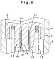
- a flow controller is formed in the valve assembly 1 in which a vapor tap 27 is formed in a side face of the outlet side chamber 14 of the housing 2.
- a vapor tap 27 is formed in a side face of the outlet side chamber 14 of the housing 2.
- the introduction hole 15 and the vapor tap 27 have to be formed with sizes such that the flow amounts of the aerosol contents into the outlet side chamber 14 is made less than the spray amount from the orifice 8.
- the vapor tap 27 is formed in the side face of the outlet side chamber 14 of the housing 2
- the vapor tap 27 is formed at the inlet side chamber 13 of the housing 2.
- the valve assembly 1 having a flow controller according to the invention is made of a double aerosol container constituted of an outer container 25 and an inner container 26.
- the outer container 25 is filled with the propellant
- the inner container 26 is filled with contents, thereby separating the contents and propellant from each other.
- the propellant in the outer container 25 has a high pressure and exerts a strong pressure to the inner container 26. This pressure makes the contents flow much into the housing 2, strongly pushes the piston 11 toward the outlet side chamber 14, and deeply inserts the controlling sleeve 16 into the insertion space 20.
- the headspace in the outer container 25 becomes larger, and therefore, the pressure in the outer container 25 is reduced, thereby weakening the pressure exerted to the inner container 26.
- the contents' pushing force exerted to the piston becomes less, and the insertion amount of the controlling sleeve 16 into the insertion space 20 becomes less, so that the flow amount of the contents can be maintained at the same level at the beginning of spraying as well as at the end of spraying.
- the flow controller can maintain a constant spray amount of the contents per unit time at any time from the beginning to the last time of spraying and make an effective flow controller, by controlling the insertion amount of the piston 11 in proportion to the pressure of the aerosol contents.
- hair preparations exemplified are a hair spray, a hair treatment, a tonic, and a hair restorer.
- Hair Spray Acrylic resin alkanol amine liquid (30%) 4.00 weight %
- Liquid paraffin 1.50 weight % Propylene glycol 0.20 weight % Methyl phenol polysiloxane 0.10 weight % Perfume 0.20 weight % 99% denatured alcohol 95.00 weight % Carbonate gas 3.00 weight %
- Polyoxyethylene setting castor oil 0.01 weight % L-menthol 0.28 weight % d1-camphor 0.05 weight % Tincture of pepper 0.05 weight % Lactic acid 0.02 weight
- Eau de Cologne Dimethyl polysiloxane 0.70 weight % POE glycerol triisostearate 1.00 weight % Perfume 2.00 weight %
- Polyoxyethylene setting castor oil (E.O 1.00 weight % 60) Ion-exchanged water 35.00 weight % 99% denatured alcohol 59.80 weight %
- Mineral Oil 60.00 weight % Carbonate gas 38.00 weight % Total 100.00 weight % Shaving cream (shave gel later foaming) Palmitic Acid 10.00 weight % Dibuthyl hydroxytoluene 0.10 weight % Oleyl alchol 1.00 weight % Glycerol 5.00 weight % Sor
- the following example is a prescription of an antiperspirant-deodorant.
- Antiperspirant - Deodorant 2,4,4'-trichloro-2-hydroxy diphenyl ether 0.20 weight % Octyl dodecanol 1.00 weight % Zinc phenol sulfonic acid 1.00 weight % Perfume 0.20 weight % 99% denatured alcohol 94.60 weight % Carbonate gas 3.00 weight % Total 100.00 weight %
- Muscular antiphlogistic L-menthol 3.00 weight % Methyl salicylate 2.70 weight % Tocopherol acetate 0.20 weight % 99% denatured alcohol 91.10 weight % Carbonate gas 3.00 weight % Total 100.00 weight % Insect repellent N, N ⁇ diethyl ⁇ m - toluamide 4.00 weight % Di- N -propyl-isocinchomeronate 1.00 weight % N-(2-ethyl hexyl)-bicyclo 2.2.1-hepta-5-en- 2.3-dicarboxyimide 2.00 weight % Polyoxyethylene glycol #400 1.50 weight % 99% denatured alcohol 88.50 weight % Carbonate gas 3.00 weight % Total 100.00 weight %
- the following examples are prescriptions of an insecticide for cockroach and an insecticide for gardening.
- Insecticide for cockroach O O ⁇ dimethyl ⁇ O - (3-methyl-4-nitrophenyl) thiophosphate 1.25 weight % Piperonyl butoxide 1.95 weight % Perfume 0.01 weight % Kerosine 93.79 weight % Carbonate gas 3.00 weight % Total 100.00 weight %
- Insecticide for gardening (1,3,4,5,6,7 ⁇ hexahydro ⁇ 1,3 dioxo ⁇ 2 ⁇ isoindolyl) methyl-dl ⁇ cis / trans -chrysanthemate 0.20 weight %
- Polyoxyalkyl phosphate 0.20weight % Isopropyl alcohol 4.00 weight % Ion-exchanged water 95.30 weight % Nitrogen 0.30 weight % Total 100.00 weight %
- the following examples are prescriptions of a deodorant for garbage and a waterproofing spray
- Deodorant for garbage Lauric methacrylate 2.00 weight % Isopropyl methylphenol 0.20 weight % Hinokitiol 0.01 weight % Dipropylene glycol 0.90 weight % Perfume 1.00 weight % 99% denatured alcohol 92.89 weight % Carbonate gas 3.00 weight % Total 100.00 weight %
- the flow controller thus constituted can always maintain the spray amount of the aerosol contents per unit time at the same level from the beginning to the last minute of spraying.
- the piston is free from pulsation or the like, and the controller can regulate the flow amount stably.
- the flow controller is incorporated in the valve assembly, which renders the structure of the aerosol container simple, thereby reducing the number of parts and working time for assembling, rendering production of the aerosol container inexpensive.
- the flow controller for aerosol container can be used for a compact aerosol container having a volume of 220 cc or less, or for a large size aerosol container having a volume of 1,000 cc or less.
- the contents that can be contained in the container in which the flow controller is used are, e.g., hair preparations, cosmetics, deodorants, antiperspirants, other human body treatment goods, insecticides, coating agents, cleaners, other goods for household, industrial materials, automobile goods, foods, etc.
- hair preparations exemplified are, e.g., hair sprays, hair dresser-conditioner, hair shampoo and conditioner, acidic hair dyes, two liquids type oxidizing permanent hair dyes, color sprays, decoloring agents, permanent treatment agents, hair restorers, hair foams, hair tonics, sprays for bad hair correction, fragrances for hair, etc.
- cosmetics exemplified are, e.g., shaving creams, after shave lotions, perfumes, eau de Cologne, facial cleansing materials, sun screens, foundations, unhair agents and decoloring agents, bath gels, toothpastes, skin care foams, etc.
- deodorants and antiperspirants exemplified are, e.g., antiperspirants, deodorants, body shampoos, etc.
- deodorants e.g., antiperspirants, deodorants, body shampoos, etc.
- other human body treatment goods exemplified are muscular antiphlogistics, skin disease treatments, dermatophytosis medicines, insect repellents, cleaners, oral agents, salves, burning medicines, etc.
- insecticides exemplified are, e.g., air-spray insecticides, insecticides for cockroach, insecticides for gardening, insecticides for ticks, pesticides for noxious insects, etc.
- coating agents exemplified are, e.g., paints for house, paints for automobile, etc.
- cleaners glass cleaners for house, carpet cleaners, bath cleaners, floor and furniture cleaners, shoe and skin cleaners, wax cleaners, etc.
- other goods for household exemplified are, e.g., room deodorants, deodorants for toilet, waterproofing agents, starches for washing, herbicides, insecticides for clothes, flame proofing agents, fire extinguishers, antifungals, etc.
- exemplified are, e.g., lubricants, anticorrosives, mold-releasing agents, etc.
- exemplified are, e.g., defrosting agents, antifreezing or thawing agents, engine cleaners, etc.
- exemplified are, e.g., pet care goods, hobby goods, amusement goods, foods such as coffee, juices, etc.
Landscapes
- Chemical & Material Sciences (AREA)
- Dispersion Chemistry (AREA)
- Engineering & Computer Science (AREA)
- Mechanical Engineering (AREA)
- Containers And Packaging Bodies Having A Special Means To Remove Contents (AREA)
- Nozzles (AREA)
- Catching Or Destruction (AREA)
Applications Claiming Priority (3)
| Application Number | Priority Date | Filing Date | Title |
|---|---|---|---|
| JP306094/97 | 1997-11-07 | ||
| JP30609497 | 1997-11-07 | ||
| JP30609497A JP3865485B2 (ja) | 1997-11-07 | 1997-11-07 | エアゾール容器用の流量調整装置 |
Publications (2)
| Publication Number | Publication Date |
|---|---|
| EP0916596A1 true EP0916596A1 (fr) | 1999-05-19 |
| EP0916596B1 EP0916596B1 (fr) | 2003-05-28 |
Family
ID=17952968
Family Applications (1)
| Application Number | Title | Priority Date | Filing Date |
|---|---|---|---|
| EP98103763A Expired - Lifetime EP0916596B1 (fr) | 1997-11-07 | 1998-03-04 | Régulateur de débit pour un récipient d'aérosol pressurisé |
Country Status (6)
| Country | Link |
|---|---|
| US (1) | US5915598A (fr) |
| EP (1) | EP0916596B1 (fr) |
| JP (1) | JP3865485B2 (fr) |
| KR (1) | KR100493656B1 (fr) |
| DE (1) | DE69815025T2 (fr) |
| TW (1) | TW370474B (fr) |
Cited By (4)
| Publication number | Priority date | Publication date | Assignee | Title |
|---|---|---|---|---|
| WO2006038615A1 (fr) | 2004-10-07 | 2006-04-13 | Mitani Valve Co., Ltd. | Unité de régulation de débit pour conteneur d’aérosol, mécanisme de régulation de débit pour conteneur d’aérosol, et produit de type aérosol |
| WO2015055906A1 (fr) * | 2013-10-18 | 2015-04-23 | L'air Liquide, Societe Anonyme Pour L'etude Et L'exploitation Des Procedes Georges Claude | Régulateur de débit gazeux, détendeur, robinet et bouteille munis d'un tel régulateur |
| WO2017162972A1 (fr) | 2016-03-23 | 2017-09-28 | Aptar France Sas | Valve doseuse et dispositif de distribution de produit fluide comportant une telle valve |
| AU2022209326B2 (en) * | 2021-09-30 | 2024-02-01 | Superior Power Tool Co., Ltd. | Bagless gas canister for gas nailer |
Families Citing this family (42)
| Publication number | Priority date | Publication date | Assignee | Title |
|---|---|---|---|---|
| US8028864B2 (en) | 1992-02-24 | 2011-10-04 | Homax Products, Inc. | Actuator systems and methods for aerosol wall texturing |
| US6883688B1 (en) | 1992-02-24 | 2005-04-26 | Homax Products, Inc. | Aerosol spray texturing systems and methods |
| US7278590B1 (en) | 1992-02-24 | 2007-10-09 | Homax Products, Inc. | Systems and methods for applying texture material to ceiling surfaces |
| JP3486383B2 (ja) * | 1999-12-17 | 2004-01-13 | 株式会社日立ユニシアオートモティブ | ガス噴射弁 |
| US6299024B1 (en) | 2000-07-05 | 2001-10-09 | Robert E. Corba | Valve assembly for dispensing container |
| US6325248B1 (en) | 2000-07-05 | 2001-12-04 | Robert E. Corba | Container assembly |
| US6357633B1 (en) | 2000-07-18 | 2002-03-19 | Precision Valve Corporation | Fast opening aerosol valve |
| US6415957B1 (en) * | 2000-11-27 | 2002-07-09 | S. C. Johnson & Son, Inc. | Apparatus for dispensing a heated post-foaming gel |
| US7157076B2 (en) * | 2002-05-31 | 2007-01-02 | L'oreal | Aerosol device comprising a hair treatment composition, and hair treatment process |
| DE60320731D1 (de) * | 2002-10-26 | 2008-06-19 | James H Martin | Einstellbares Dosierventil zur Abgabe von unter Druck stehenden Flüssigkeiten |
| US6953299B2 (en) * | 2003-01-16 | 2005-10-11 | The Clorox Company | Cleaning implement with interchangeable tool heads |
| US7007338B2 (en) * | 2003-01-16 | 2006-03-07 | Garabedian Jr Aram | Advanced aerosol cleaning system |
| US7500621B2 (en) | 2003-04-10 | 2009-03-10 | Homax Products, Inc. | Systems and methods for securing aerosol systems |
| US20050019724A1 (en) * | 2003-07-25 | 2005-01-27 | Lawler David E. | Tooth powdering applicator with nozzle spray control |
| US20050056708A1 (en) * | 2003-09-12 | 2005-03-17 | Castillo Higareda Jose De Jesus | Apparatus for inducing turbulence in a fluid and method of manufacturing same |
| US20050161531A1 (en) | 2004-01-28 | 2005-07-28 | Greer Lester R.Jr. | Texture material for covering a repaired portion of a textured surface |
| US7677420B1 (en) | 2004-07-02 | 2010-03-16 | Homax Products, Inc. | Aerosol spray texture apparatus for a particulate containing material |
| US7487893B1 (en) | 2004-10-08 | 2009-02-10 | Homax Products, Inc. | Aerosol systems and methods for dispensing texture material |
| KR100776770B1 (ko) | 2006-07-18 | 2007-11-29 | (주)비엔에프 | 고압분사 에어로졸 밸브 |
| CN101595047B (zh) * | 2007-01-31 | 2011-05-11 | Ips专利股份公司 | 用于分配加压流体的剂量的计量装置 |
| US8344056B1 (en) | 2007-04-04 | 2013-01-01 | Homax Products, Inc. | Aerosol dispensing systems, methods, and compositions for repairing interior structure surfaces |
| US8580349B1 (en) | 2007-04-05 | 2013-11-12 | Homax Products, Inc. | Pigmented spray texture material compositions, systems, and methods |
| US9382060B1 (en) | 2007-04-05 | 2016-07-05 | Homax Products, Inc. | Spray texture material compositions, systems, and methods with accelerated dry times |
| US20090239180A1 (en) * | 2007-06-26 | 2009-09-24 | Lim Walter K | Aerosol candle snuffer using non-flammable gas |
| BE1017888A3 (nl) * | 2007-10-05 | 2009-10-06 | Kerstens Peter | Een verdeler en samenstelling voor het bereiden van ijskoffie. |
| US7959041B2 (en) * | 2008-08-26 | 2011-06-14 | S. C. Johnson & Son, Inc. | Valve assembly for pressurized dispensers |
| US8447250B2 (en) * | 2009-06-09 | 2013-05-21 | Broadcom Corporation | Method and system for an integrated voltage controlled oscillator-based transmitter and on-chip power distribution network |
| GB0913488D0 (en) * | 2009-08-01 | 2009-09-16 | Reckitt Benckiser Nv | Product |
| WO2011070690A1 (fr) * | 2009-12-09 | 2011-06-16 | 東洋エアゾール工業株式会社 | Dispositif de remplissage d'agent propulseur |
| GB201101006D0 (en) | 2011-01-21 | 2011-03-09 | Reckitt Benckiser Nv | Product |
| JP2012166787A (ja) * | 2011-02-09 | 2012-09-06 | Mitani Valve Co Ltd | 粉状内容物詰まり防止機構および粉状内容物詰まり防止機構を備えたエアゾール式製品 |
| US8827122B2 (en) | 2011-04-15 | 2014-09-09 | The Clorox Company | Non-flammable plastic aerosol |
| US9156042B2 (en) | 2011-07-29 | 2015-10-13 | Homax Products, Inc. | Systems and methods for dispensing texture material using dual flow adjustment |
| US9248457B2 (en) | 2011-07-29 | 2016-02-02 | Homax Products, Inc. | Systems and methods for dispensing texture material using dual flow adjustment |
| US9156602B1 (en) | 2012-05-17 | 2015-10-13 | Homax Products, Inc. | Actuators for dispensers for texture material |
| US9435120B2 (en) | 2013-03-13 | 2016-09-06 | Homax Products, Inc. | Acoustic ceiling popcorn texture materials, systems, and methods |
| CA2859537C (fr) | 2013-08-19 | 2019-10-29 | Homax Products, Inc. | Materiaux, systemes et procedes de texture pour plafond |
| USD787326S1 (en) | 2014-12-09 | 2017-05-23 | Ppg Architectural Finishes, Inc. | Cap with actuator |
| US10793343B1 (en) * | 2018-06-08 | 2020-10-06 | Nelson Alonso | Aerosol valve |
| FR3099144B1 (fr) * | 2019-07-24 | 2022-01-07 | Lindal France | Valve pour récipient sous pression |
| EP4190716A1 (fr) | 2019-07-24 | 2023-06-07 | Lindal France SAS | Coupelle de valve pour récipient sous pression |
| JP7633665B2 (ja) * | 2021-06-17 | 2025-02-20 | 株式会社ダイゾー | 吐出製品 |
Citations (5)
| Publication number | Priority date | Publication date | Assignee | Title |
|---|---|---|---|---|
| US3830412A (en) * | 1971-03-16 | 1974-08-20 | E H Green | Aerosol valve and sprayhead |
| US4393984A (en) * | 1979-09-20 | 1983-07-19 | Aerosol Inventions And Development As Aid Sa | Vapor tap valve for aerosols |
| US4969577A (en) * | 1987-06-26 | 1990-11-13 | Werding Winfried J | Apparatus to provide for the storage and the controlled delivery of products that are under pressure |
| JPH0858859A (ja) * | 1994-08-19 | 1996-03-05 | Toyo Aerosol Kogyo Kk | エアゾール用流通量調整装置 |
| US5653963A (en) * | 1991-12-13 | 1997-08-05 | L'oreal | Aerosol system for hair lacquer |
Family Cites Families (3)
| Publication number | Priority date | Publication date | Assignee | Title |
|---|---|---|---|---|
| US3520450A (en) * | 1968-06-06 | 1970-07-14 | Dart Ind Inc | Fluids dispensing valve |
| US3666148A (en) * | 1969-10-13 | 1972-05-30 | Gillette Co | Aerosol valve with safety relief device |
| US5605258A (en) * | 1986-12-03 | 1997-02-25 | Abplanalp; Robert H. | Two-piece aerosol valve for vertical or tilt action |
-
1997
- 1997-11-07 JP JP30609497A patent/JP3865485B2/ja not_active Expired - Fee Related
-
1998
- 1998-03-04 EP EP98103763A patent/EP0916596B1/fr not_active Expired - Lifetime
- 1998-03-04 DE DE69815025T patent/DE69815025T2/de not_active Expired - Lifetime
- 1998-03-05 US US09/035,414 patent/US5915598A/en not_active Expired - Lifetime
- 1998-04-17 TW TW087105853A patent/TW370474B/zh not_active IP Right Cessation
- 1998-05-21 KR KR10-1998-0018400A patent/KR100493656B1/ko not_active Expired - Fee Related
Patent Citations (5)
| Publication number | Priority date | Publication date | Assignee | Title |
|---|---|---|---|---|
| US3830412A (en) * | 1971-03-16 | 1974-08-20 | E H Green | Aerosol valve and sprayhead |
| US4393984A (en) * | 1979-09-20 | 1983-07-19 | Aerosol Inventions And Development As Aid Sa | Vapor tap valve for aerosols |
| US4969577A (en) * | 1987-06-26 | 1990-11-13 | Werding Winfried J | Apparatus to provide for the storage and the controlled delivery of products that are under pressure |
| US5653963A (en) * | 1991-12-13 | 1997-08-05 | L'oreal | Aerosol system for hair lacquer |
| JPH0858859A (ja) * | 1994-08-19 | 1996-03-05 | Toyo Aerosol Kogyo Kk | エアゾール用流通量調整装置 |
Non-Patent Citations (1)
| Title |
|---|
| PATENT ABSTRACTS OF JAPAN vol. 096, no. 007 31 July 1996 (1996-07-31) * |
Cited By (10)
| Publication number | Priority date | Publication date | Assignee | Title |
|---|---|---|---|---|
| WO2006038615A1 (fr) | 2004-10-07 | 2006-04-13 | Mitani Valve Co., Ltd. | Unité de régulation de débit pour conteneur d’aérosol, mécanisme de régulation de débit pour conteneur d’aérosol, et produit de type aérosol |
| EP1818279A4 (fr) * | 2004-10-07 | 2008-07-23 | Mitani Valve Co Ltd | Unite de regulation de debit pour conteneur d'aerosol, mecanisme de regulation de debit pour conteneur d'aerosol, et produit de type aerosol |
| WO2015055906A1 (fr) * | 2013-10-18 | 2015-04-23 | L'air Liquide, Societe Anonyme Pour L'etude Et L'exploitation Des Procedes Georges Claude | Régulateur de débit gazeux, détendeur, robinet et bouteille munis d'un tel régulateur |
| FR3012196A1 (fr) * | 2013-10-18 | 2015-04-24 | Air Liquide | Regulateur de debit gazeux, detendeur, robinet et bouteille munis un tel regulateur |
| CN105637269A (zh) * | 2013-10-18 | 2016-06-01 | 乔治洛德方法研究和开发液化空气有限公司 | 气体流调节器、减压阀、阀和安装有这种调节器的瓶 |
| WO2017162972A1 (fr) | 2016-03-23 | 2017-09-28 | Aptar France Sas | Valve doseuse et dispositif de distribution de produit fluide comportant une telle valve |
| FR3049275A1 (fr) * | 2016-03-23 | 2017-09-29 | Aptar France Sas | Valve doseuse et dispositif de distribution de produit fluide comportant une telle valve |
| CN108778957A (zh) * | 2016-03-23 | 2018-11-09 | 阿普塔尔法国简易股份公司 | 计量阀和包括这种阀的流体产品分配装置 |
| US10745189B2 (en) | 2016-03-23 | 2020-08-18 | Aptar France Sas | Metering valve and fluid product dispensing device comprising such a valve |
| AU2022209326B2 (en) * | 2021-09-30 | 2024-02-01 | Superior Power Tool Co., Ltd. | Bagless gas canister for gas nailer |
Also Published As
| Publication number | Publication date |
|---|---|
| KR19990044738A (ko) | 1999-06-25 |
| DE69815025T2 (de) | 2004-04-01 |
| JP3865485B2 (ja) | 2007-01-10 |
| DE69815025D1 (de) | 2003-07-03 |
| KR100493656B1 (ko) | 2005-10-04 |
| TW370474B (en) | 1999-09-21 |
| JPH11139471A (ja) | 1999-05-25 |
| EP0916596B1 (fr) | 2003-05-28 |
| US5915598A (en) | 1999-06-29 |
Similar Documents
| Publication | Publication Date | Title |
|---|---|---|
| EP0916596B1 (fr) | Régulateur de débit pour un récipient d'aérosol pressurisé | |
| EP0796804B1 (fr) | Valve pour récipient aérosol | |
| EP0972723B1 (fr) | Récipient-aérosol à double chambre et son procédé de fabrication | |
| US4511069A (en) | Dispensing system | |
| EP2183053B2 (fr) | Aérosols | |
| US10029844B2 (en) | Aerosol housing mechanism and aerosol-type product having the aerosol housing mechanism | |
| US4354638A (en) | Spiral actuator for aerosol powdered suspension product | |
| DE69822147T2 (de) | Doppelkammeraerosolbehälter | |
| US6092566A (en) | Double chamber aerosol container and manufacturing method therefor | |
| US10994922B2 (en) | Metering valve mechanism of aerosol container and aerosol type product with said metering valve mechanism | |
| JP5055577B2 (ja) | 定量バルブ機構および、この定量バルブ機構を備えたエアゾール式製品 | |
| JP4974175B2 (ja) | 流量レギュレータユニットおよびこの流量レギュレータユニットを備えたエアゾール式製品 | |
| EP3486193B1 (fr) | Mécanisme de soupape renversable de type aérosol et produit aérosol muni dudit mécanisme de soupape renversable | |
| DE69711839T2 (de) | Druckgasbehälter mit zwei Ventilen | |
| JP2006289302A (ja) | チップストップ機構,チップストップ機構を備えたポンプ式製品および、チップストップ機構を備えたエアゾール式製品 | |
| JP6859574B2 (ja) | 圧縮ガス対応の内容物ドロップ放出構造およびこの内容物ドロップ放出構造を備えた圧縮ガス式製品 | |
| JP6762141B2 (ja) | 内容物噴射操作用ボタンおよびこの内容物噴射操作用ボタンを備えたエアゾール式製品 | |
| KR20220044240A (ko) | 에어졸 용기의 역 정량 분사 기구 및 이 역 정량 분사 기구를 구비한 에어졸식 제품 | |
| WO2020044532A1 (fr) | Mécanisme de pulvérisation dosée destiné à un récipient d'aérosol, et produit aérosol muni du mécanisme de pulvérisation dosée | |
| CA1190194A (fr) | Systeme debiteur | |
| JP2023129760A (ja) | 定量噴射機構および、この定量噴射機構を備えたエアゾール式製品 | |
| JP2000161516A (ja) | エアゾール容器用バルブ装置 | |
| HK1029091B (en) | Double chamber aerosol container and manufacturing method therefor |
Legal Events
| Date | Code | Title | Description |
|---|---|---|---|
| PUAI | Public reference made under article 153(3) epc to a published international application that has entered the european phase |
Free format text: ORIGINAL CODE: 0009012 |
|
| AK | Designated contracting states |
Kind code of ref document: A1 Designated state(s): CH DE FR GB IT LI |
|
| AX | Request for extension of the european patent |
Free format text: AL;LT;LV;MK;RO;SI |
|
| 17P | Request for examination filed |
Effective date: 19990722 |
|
| AKX | Designation fees paid |
Free format text: CH DE FR GB IT LI |
|
| GRAH | Despatch of communication of intention to grant a patent |
Free format text: ORIGINAL CODE: EPIDOS IGRA |
|
| GRAH | Despatch of communication of intention to grant a patent |
Free format text: ORIGINAL CODE: EPIDOS IGRA |
|
| GRAA | (expected) grant |
Free format text: ORIGINAL CODE: 0009210 |
|
| AK | Designated contracting states |
Designated state(s): CH DE FR GB IT LI |
|
| REG | Reference to a national code |
Ref country code: GB Ref legal event code: FG4D |
|
| REG | Reference to a national code |
Ref country code: CH Ref legal event code: EP |
|
| REF | Corresponds to: |
Ref document number: 69815025 Country of ref document: DE Date of ref document: 20030703 Kind code of ref document: P |
|
| REG | Reference to a national code |
Ref country code: CH Ref legal event code: NV Representative=s name: TROESCH SCHEIDEGGER WERNER AG |
|
| ET | Fr: translation filed | ||
| PLBE | No opposition filed within time limit |
Free format text: ORIGINAL CODE: 0009261 |
|
| STAA | Information on the status of an ep patent application or granted ep patent |
Free format text: STATUS: NO OPPOSITION FILED WITHIN TIME LIMIT |
|
| 26N | No opposition filed |
Effective date: 20040302 |
|
| PG25 | Lapsed in a contracting state [announced via postgrant information from national office to epo] |
Ref country code: IT Free format text: LAPSE BECAUSE OF NON-PAYMENT OF DUE FEES Effective date: 20080304 |
|
| PGFP | Annual fee paid to national office [announced via postgrant information from national office to epo] |
Ref country code: FR Payment date: 20110404 Year of fee payment: 14 Ref country code: CH Payment date: 20110324 Year of fee payment: 14 |
|
| PGFP | Annual fee paid to national office [announced via postgrant information from national office to epo] |
Ref country code: GB Payment date: 20110321 Year of fee payment: 14 Ref country code: DE Payment date: 20110325 Year of fee payment: 14 |
|
| PGFP | Annual fee paid to national office [announced via postgrant information from national office to epo] |
Ref country code: IT Payment date: 20110329 Year of fee payment: 14 |
|
| REG | Reference to a national code |
Ref country code: CH Ref legal event code: PL |
|
| GBPC | Gb: european patent ceased through non-payment of renewal fee |
Effective date: 20120304 |
|
| REG | Reference to a national code |
Ref country code: FR Ref legal event code: ST Effective date: 20121130 |
|
| REG | Reference to a national code |
Ref country code: DE Ref legal event code: R119 Ref document number: 69815025 Country of ref document: DE Effective date: 20121002 |
|
| PG25 | Lapsed in a contracting state [announced via postgrant information from national office to epo] |
Ref country code: GB Free format text: LAPSE BECAUSE OF NON-PAYMENT OF DUE FEES Effective date: 20120304 Ref country code: CH Free format text: LAPSE BECAUSE OF NON-PAYMENT OF DUE FEES Effective date: 20120331 Ref country code: FR Free format text: LAPSE BECAUSE OF NON-PAYMENT OF DUE FEES Effective date: 20120402 Ref country code: LI Free format text: LAPSE BECAUSE OF NON-PAYMENT OF DUE FEES Effective date: 20120331 |
|
| PG25 | Lapsed in a contracting state [announced via postgrant information from national office to epo] |
Ref country code: IT Free format text: LAPSE BECAUSE OF NON-PAYMENT OF DUE FEES Effective date: 20120304 |
|
| PG25 | Lapsed in a contracting state [announced via postgrant information from national office to epo] |
Ref country code: DE Free format text: LAPSE BECAUSE OF NON-PAYMENT OF DUE FEES Effective date: 20121002 |