EP0916611A2 - Verfahren zum Betreiben einer Kreuzspulen herstellenden Textilmaschine sowie Vorrichtung für eine solche Textilmaschine - Google Patents
Verfahren zum Betreiben einer Kreuzspulen herstellenden Textilmaschine sowie Vorrichtung für eine solche Textilmaschine Download PDFInfo
- Publication number
- EP0916611A2 EP0916611A2 EP98118040A EP98118040A EP0916611A2 EP 0916611 A2 EP0916611 A2 EP 0916611A2 EP 98118040 A EP98118040 A EP 98118040A EP 98118040 A EP98118040 A EP 98118040A EP 0916611 A2 EP0916611 A2 EP 0916611A2
- Authority
- EP
- European Patent Office
- Prior art keywords
- cross
- transport device
- ultrasonic sensor
- changer
- coil
- Prior art date
- Legal status (The legal status is an assumption and is not a legal conclusion. Google has not performed a legal analysis and makes no representation as to the accuracy of the status listed.)
- Withdrawn
Links
Images


Classifications
-
- B—PERFORMING OPERATIONS; TRANSPORTING
- B65—CONVEYING; PACKING; STORING; HANDLING THIN OR FILAMENTARY MATERIAL
- B65H—HANDLING THIN OR FILAMENTARY MATERIAL, e.g. SHEETS, WEBS, CABLES
- B65H67/00—Replacing or removing cores, receptacles, or completed packages at paying-out, winding, or depositing stations
- B65H67/04—Arrangements for removing completed take-up packages and or replacing by cores, formers, or empty receptacles at winding or depositing stations; Transferring material between adjacent full and empty take-up elements
- B65H67/0405—Arrangements for removing completed take-up packages or for loading an empty core
- B65H67/0411—Arrangements for removing completed take-up packages or for loading an empty core for removing completed take-up packages
-
- B—PERFORMING OPERATIONS; TRANSPORTING
- B65—CONVEYING; PACKING; STORING; HANDLING THIN OR FILAMENTARY MATERIAL
- B65H—HANDLING THIN OR FILAMENTARY MATERIAL, e.g. SHEETS, WEBS, CABLES
- B65H2553/00—Sensing or detecting means
- B65H2553/30—Sensing or detecting means using acoustic or ultrasonic elements
-
- B—PERFORMING OPERATIONS; TRANSPORTING
- B65—CONVEYING; PACKING; STORING; HANDLING THIN OR FILAMENTARY MATERIAL
- B65H—HANDLING THIN OR FILAMENTARY MATERIAL, e.g. SHEETS, WEBS, CABLES
- B65H2701/00—Handled material; Storage means
- B65H2701/30—Handled filamentary material
- B65H2701/31—Textiles threads or artificial strands of filaments
Definitions
- the invention relates to a method for operating a Cross-wound textile machine according to the preamble of claim 1 or a device for a such a textile machine according to the preamble of claim 6.
- Such textile machines for example automatic winder, are for example by DE 195 12 891 A1 or DE 195 20 133 A1 known.
- the package changer transfers finished Cross-wound bobbins from the winding device of a job to one machine-long, arranged behind the winding devices Cross-coil transport device and then changes a new temporary storage location Empty tube into the winding device.
- the cross reel changer points accordingly DE 195 12 891 A1 a sensor device in the form of a Light button on.
- Cross-coil transport device before initiating the Cross-wound process scanned. That is, the package change process is only then started when determined using the sensor device was that the relevant storage space on the package transport device free is.
- a comparable sensor device is in connection with an open-end spinning machine also in DE 37 31 125 A1 described. This also applies to this known textile machine mobile control unit a sensor device for scanning a package transport device.
- the Sensor device is either mechanical Push button or as a photoelectric sensor element educated.
- photoelectric Sensor devices can be avoided because such Work sensor devices without contact; optical
- facilities are known to be very sensitive against pollution.
- photoelectric sensor devices a regular, careful maintenance, otherwise the malfunction of the Sensor devices can hardly be prevented.
- Another disadvantage of photoelectric light sensors is that that such sensor devices strongly from the coloring of the object to be scanned are dependent. That is, bright objects are detected much more reliably than dark objects. Frosted black objects are almost impossible to detect.
- Non-contact sensor devices are from the general mechanical engineering also in the form of so-called Ultrasonic proximity switch known. Such ultrasonic proximity switches can be used in objects Record distances between approx. 6 and 600 cm. Ultrasonic proximity switches are commercially available Components whose function, for example in a prospectus Siemens company (Siemens NS 3, 1991), is explained.
- DE 39 32 665 A1 relates to a person and Collision protection device for an automatically working Control unit of a ring spinning machine.
- the control unit has one at each electronic control unit connected electro-acoustic Transducer that delivers a two-part transmit sound signal.
- a sound measurement signal is emitted in the direction of travel, while a sound reference signal on a reference reflector, for example the hall floor.
- the electronic control unit delivers a detection signal or directs a reversal of the direction of travel Control unit on if on before the reference runtime expires Sound signal is received because such a sound signal indicates an obstacle in the travel path of the control unit. There remains a sound signal until the expiry of the Reference sound signal off, the control unit signals one Error and shuts down the control unit.
- the Invention the object of a method for operating to develop a textile machine producing cross-wound bobbins or a device for such a textile machine to create the the known methods / devices improved.
- this object is achieved by a method as described in claim 1 or by a Apparatus according to claim 6.
- Preferred embodiments of the device are in the Subclaims 7 to 11 described.
- the first step is to work with a reference sound signal, that is to say with a sound signal which is sent over a measuring section whose exact length is known. Since both the length of this measuring section and the running time of a sound signal are known via this measuring path under certain climatic conditions, any deviation in the running time of the reference sound signal immediately allows conclusions to be drawn about the prevailing climatic conditions, which are taken into account as a correction value when evaluating the running time of a subsequent measuring sound signal will. Based on the correspondingly corrected sample value, it is then possible to make a reliable statement about the respective loading condition of the relevant storage area of the cross-wound bobbin transport device.
- the maximum and the minimum permissible distances between the ultrasonic sensor and the transport device are first determined and fed into the control device of the package changer.
- This so-called large tolerance range takes into account all height deviations of the transport device that can occur due to machine tolerances as well as all measurement errors due to possible climatic conditions.
- the control device then becomes quasi calibrated ", that is to say, the transport device is scanned by the ultrasonic sensor. All the scanned values in the range of the maximum permissible distance are stored in the stone device, which permanently forms an average value therefrom. This average value corresponds to the average distance of the cross-coil removal belt from the ultrasonic sensor of the cross-coil changer .
- a so-called tolerance band is placed around this mean value, the width of which only takes into account height differences due to permissible machine tolerances.
- the device according to the invention which is described in claim 6, has the particular advantage that important parts of the monitoring device, preferably the control device, are already present on the cross-wound bobbin changer and can be used without major design effort. It is only necessary to set the existing control device of the interchangeable unit in software to the ultrasonic sensor. The computing capacity of the control device is in any case sufficient to be able to take on this additional task without any problems.
- the Ultrasonic sensor designed so that it is used to 'calibrate' the Ultrasonic sensor device first a reference sound signal emits that in the control device into a correction value is implemented. That is, based on the term of the Reference sound signal is in the control device on the prevailing climatic conditions closed.
- This correction value is then used during normal Operation of the package changer when evaluating the Running time of a measurement sound signal is taken into account (claim 7).
- a reference path is formed in the scanning area of the ultrasonic sensor.
- a sound-reflecting component which is arranged, for example, on a handling device of the cross-wound bobbin changer and whose distance from the ultrasonic sensor is predetermined by the design and is therefore precisely known, is swiveled into the area of the sound cone of the ultrasonic sensor or traverses the scanning area as a result of the process.
- a reflector can be used to form a Reference route through another, if necessary additional component to be installed on the package changer be formed.
- the distance of the Ultrasonic sensor from the package conveyor belt advantageously be chosen so that the sound cone in Area of the packages of the packages on the package transport device has a width which is approximately that Division of the jobs of the textile machine corresponds.
- the winding unit 2 is a total in side view with the reference number 1 textile machine, in present case of an automatic winder.
- Such winding machines as is known, have one A large number of similar types arranged side by side Jobs 2, which have a machine's own Kops- and Sleeve transport system 3 are supplied with supply spools 9.
- the delivered spinning heads 9 are in one Unwinding position 10 of the winding units 2 too large Cross-wound bobbins 11.
- the individual winding units have as known, and therefore only hinted at about different Facilities that ensure the proper operation of this Ensure jobs.
- Fig. 1 for example, with 12 is a suction nozzle, with 13 one Splicing device, with 14 a thread tensioning device, with 15 a thread cleaner with thread cutting device and with 16 one Paraffinizing device indicated.
- the bobbin drive drum which drives the cross-wound bobbin 11 by friction, bears the reference number 17.
- the bobbin wound 11 is held in a bobbin frame 18 which is pivotally mounted about an axis 19.
- a swivel plate 20 is arranged below the coil frame 18, likewise rotatable to a limited extent about the swivel axis 19.
- Behind the winding units 2 there is a cross-wound bobbin transport device 21, onto which the finished bobbins 11 are discharged and transported to a loading station (not shown) arranged on the machine end.
- Such known cross-wound bobbin transport devices 21 generally have an endless conveyor belt with a troughed transport strand 33 and a return strand 35.
- Each winding unit 2 also does not have one in FIG. 1 illustrated temporary storage 22 in the Cross bobbin empty sleeves 44 are provided. Furthermore are the individual winding units 2 each with internal Spooling computers 39 equipped, the rewinding process control and with a central control unit 45 the Connect the winder 1.
- the winding units 2 are over a service unit, for example, a cross-wound bobbin changer 23.
- Cross-coil changer 23 ensures that cross-wound bobbins 11, the have reached a certain diameter on the Cross-coil transport device 21 are carried out and that then a new one from a buffer 22 Empty sleeve 44 is replaced in the coil frame 18.
- the change unit 23 that is, the Frame opener 29, frame lifter 32, empty-case gripper 31 and the coil guide arm 41 shown.
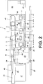
- FIG. 2 schematically shows a top view of the textile machine that produces cross-wound bobbins, in the present case a cross-wound winder 1.
- Such automatic winding machines 1 have end frames 36, 37, in which the drive and control devices or the suction devices are arranged and which are connected via a suction traverse 40.
- a plurality of so-called bobbin case housings 42 are fastened to the suction traverse 40 in a row next to one another.
- a cross-wound bobbin transport device 21 is installed above the suction traverse 40, that is, behind the winding devices of the winding units 2, the transport direction of which is indicated by the arrow 43.
- a cross-wound bobbin 23 stored in the Completed cross-wound bobbins 11 from the Spool frame 18 takes and on the package spool 21 transferred.
- the bobbin changer 23 have, as usual, one own control device 38, which via a so-called (not shown) machine bus with both the central Control unit 45 of the automatic winder 1 and with the individual winding unit computers 46 of the winding units 2 connected is.
- the control device 38 of the cross-wound bobbin changer 23 is also connected via a signal line 28 to an ultrasonic sensor 30, which monitors the loading state of the cross-wound bobbin transport device 21.
- the ultrasonic measuring device 30, 38 of the cross-wound bobbin changer 23 according to the invention automatically takes into account the climatic conditions prevailing at the location of the textile machine in its ultrasonic measurements, as will be explained below.
- the ultrasonic measuring device 30, 38 is 'calibrated'. This means that the ultrasonic measuring device 30, 38 according to the invention is adjusted to the environmental conditions prevailing at the location of the textile machine, or, for example, after a somewhat longer standstill of the textile machine to the environmental conditions which could have changed since the last operation of the machine.
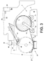
- the package changer 23 swivels for example, as indicated in FIG. 3 or 4, initially his coil guide arm 41 from that shown in Fig. 1 Zero position in that shown in Fig. 3 and Fig.4 Intermediate position.
- the ultrasonic sensor 30 As indicated in Fig. 3, is on the coil guide arm 41 Angle plate 48 or the like arranged one Reflector for the sound cone 47 of the ultrasonic sensor 30 forms.
- the distance between the ultrasonic sensor 30 and the Angle plate 48 is predetermined by design and therefore exactly known; it forms a reference measuring point R.
- the runtime is one of the ultrasonic sensor 30 sound signal radiated onto the reflector under certain that influence the propagation of sound waves known climatic conditions.
- a reference sound signal is emitted via the ultrasound sensor 30, which hits the reflector 48 and is reflected back by the latter to the ultrasound sensor 30.
- the running time of the reference sound signal which arises under the prevailing climatic conditions is determined in the control device 38 of the cross-wound bobbin changer 23 with the known running time of a corresponding one Normal "climatic conditions sound signal compared, and processed any runtime deviations in the control device 38 to determine the prevailing climatic conditions, that is, to create a correction value.
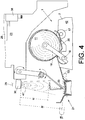
- the embodiment in FIG. 4 is comparable to the embodiment in FIG. 3.
- the reference path R is not formed by the distance from an additional angle plate 48 arranged on the cross-coil guide arm 41 to the ultrasonic sensor 30, but by the likewise known distance of the coil guide wire 49 which is rotatably arranged at the end on the cross-coil guide arm 41.
- This coil guide wire 49 stabilizes during of the cross-wound bobbin changing process conical cross-wound bobbin 11 when they are removed from the bobbin frame 18 and transferred to the cross-wound bobbin transport device 21. That is, the coil guide wire 49 is moved at a known distance from the ultrasonic sensor 30 by its sound cone 47.
- the minimum and the maximum permissible distances (A min , A max ) between the ultrasonic sensor 30 and the transport strand 33 of the cross-coil transport device 21 are first defined and as large tolerance range "(GT) is fed into the control device 38 of the package changer 23.
- This large tolerance range (GT) takes into account all deviations occurring due to machine tolerances as well as all measurement errors arising due to the climatic conditions.
- the ultrasonic sensor 30 of the interchangeable unit 23 cyclically scans the transport strand 33 (samples Z 1 to Z 7 ).
- the within the large tolerance range "(GT) lying sample values here: Z 1 , Z 2 , Z 3 , Z 6 ) are stored and continuously processed in the control device 38 to form an average value (MW).
- the measured values which refer to a loaded transport strand 33 ( Z 4 , Z 5 , Z 7 ) are not taken into account.
- MW the mean distance of the Transport strand 33 from the ultrasonic sensor 30
- tolerance band TB which is only permissible Height deviations of the transport device due to Installation tolerances taken into account.
- a bobbin 11 has reached its prescribed diameter at a winding unit 2 of the textile machine 1
- the bobbin 11 is lifted from the drive drum 17 via a bobbin lifting device (not shown) and runs to a standstill, braked or unbraked.
- the cross-wound bobbin changer 23 arranged movably on the superstructure of the winding machine 1 is requested.
- the request of the cross-wound bobbin changer 23 can also take place preventively, that is to say the request signal can be issued before the cross-wound bobbin 11 has reached its final diameter.
- the bobbin changer 23 which, as already explained above, has, among other things, handling devices for changing the finished bobbin 11 against an empty tube 44, is positioned in front of the winding station in question and first checks whether the storage area behind the winding station on the bobbin transport device 21 is free is. This means that the cross-wound bobbin changer 23 scans the relevant bobbin storage area on the cross-wound bobbin transport device 21 with its ultrasonic sensor 30. The sample value measured is corrected taking into account the climatic conditions determined by the previous reference sound measurement and compared in the control device 38 with an average distance M between the ultrasound sensor 30 and the transport strand 33 of the cross-coil transport device 21. In order to compensate for height-related deviations of the transport run 33, a tolerance band TB, which takes into account the machine tolerances, was placed around this mean value M.
- Sampling values lying above the tolerance band TB indicate a malfunction of the ultrasonic measuring device.
- the causes can be, for example, a bent one Sensor holder, an incorrectly set sensor, a defective one Sensor or the like. In this case too, none Cross bobbin change instead.
- the package changer 23 shows one such interference rather optically and / or acoustically.
Landscapes
- Replacing, Conveying, And Pick-Finding For Filamentary Materials (AREA)
- Treatment Of Fiber Materials (AREA)
- Controlling Rewinding, Feeding, Winding, Or Abnormalities Of Webs (AREA)
- Filamentary Materials, Packages, And Safety Devices Therefor (AREA)
Abstract
Description
Da sowohl die Länge dieser Meßstrecke als auch die Laufzeit eines Schallsignals über diese Meßstecke unter bestimmten Klimabedingungen bekannt sind, läßt jede Abweichung der Laufzeit des Referenzschallsignals sofort Rückschlüsse auf die augenblicklich herrschenden klimatischen Bedingungen zu, die bei der Auswertung der Laufzeit eines nachfolgenden Meßschallsignals als Korrekturwert berücksichtigt werden. Anhand des entsprechend korrigierten Abtastwertes ist dann eine zuverlässige Aussage über den jeweiligen Beladungszustand des betreffenden Ablagebereiches der Kreuzspulen-Transportvorrichtung möglich.
Anschließend wird die Steuereinrichtung quasi

Um diesen Mittelwert wird schließlich ein sogenanntes Toleranzband gelegt, dessen Breite nur noch Höhendifferenzen aufgrund zulässiger Maschinentoleranzen berücksichtigt.
Es ist lediglich notwendig, die vorhandene Steuereinrichtung des Wechselaggregates softwaremäßig auf den Ultraschallsensor einzustellen. Die Rechnerkapazität der Steuereinrichtung ist dabei in jedem Fall ausreichend, um problemlos auch diese zusätzliche Aufgabe mitübernehmen zu können.
Das heißt, ein beispielsweise an einer Handhabungseinrichtung des Kreuzspulenwechslers angeordnetes, schallreflektierendes Bauteil, dessen Abstand vom Ultraschallsensor konstruktionsbedingt vorgegeben und damit exakt bekannt ist, wird in den Bereich des Schallkegels des Ultraschallsensors eingeschwenkt bzw. durchquert den Tastbereich ablaufbedingt.
- Fig. 1
- eine Seitenansicht einer Kreuzspulen herstellenden Textilmaschine, mit einem an einer Arbeitsstelle positionierten Kreuzspulenwechsler, der mit seinem Ultraschallsensor die Kreuzspulen-Transportvorrichtung abtastet,
- Fig. 2
- eine schemastische Draufsicht auf die Einrichtung gemäß Fig. 1,
- Fig. 3
- einen Kreuzspulenwechsler, an dessen Kreuzspulenführungsarm als Reflektorelement ein Winkelblech angeordnet ist,
- Fig.4
- einen Kreuzspulenwechsler, mit einem endseitig am Kreuzspulenführungsarm angeordneten Spulenleitdraht als Reflektorelement,
- Fig. 5a - 5c
- schematisch den zeitlichen und funktionellen Ablauf einer Variante des erfindungsgemäßen Verfahrens.
Hinter den Spulstellen 2 verläuft eine Kreuzspulen-Transportvorrichtung 21, auf die die fertiggestellten Kreuzspulen 11 ausgetragen und zu einer maschinenendseitig angeordneten (nicht dargestellten) Verladestation befördert werden. Solche an sich bekannten Kreuzspulen-Transporteinrichtungen 21 besitzen in der Regel ein Endlostransportband mit einem gemuldeten Transporttrum 33 sowie einem Rücklauftrum 35.
Solche Kreuzspulautomaten 1 verfügen über Endgestelle 36, 37, in denen die Antriebs- und Steuereinrichtungen beziehungsweise die Absaugeinrichtungen angeordnet sind und die über eine Saugtraverse 40 in Verbindung stehen. An der Saugtraverse 40 sind, in Reihe nebeneinander, eine Vielzahl von sogenannten Spulstellengehäusen 42 befestigt. Oberhalb der Saugtraverse 40, das heißt, hinter den Spuleinrichtungen der Spulstellen 2, ist eine Kreuzspulen-Transportvorrichtung 21 installiert, deren Transportrichtung durch den Pfeil 43 angedeutet ist.
Die erfindungsgemäße Ultraschallmeßeinrichtung 30,38 des Kreuzspulenwechslers 23 berücksichtigt bei ihren Ultraschallmessungen dabei, wie nachfolgend noch erläutert werden wird, automatisch die jeweils am Standort der Textilmaschine herrschenden klimatischen Bedingungen .
Das heißt, die erfindungsgemäße Ultraschallmeßeinrichtung 30,38 wird auf die am Standort der Textilmaschine gegebenen Umweltbedingungen eingestellt, oder beispielsweise nach einem etwas längerem Stillstand der Textilmaschine wieder auf die Umweltbedingungen, die sich seit dem letzten Betrieb der Maschine auch geändert haben könnten, angepaßt.
Die Referenzstrecke R wird beim Ausführungsbeispiel der Fig. 4 allerdings nicht durch den Abstand eines am Kreuzspulenführungsarm 41 angeordneten, zusätzlichen Winkelbleches 48 zum Ultraschallsensor 30 gebildet, sondern durch den ebenfalls bekannten Abstand des endseitig am Kreuzspulenführungsarm 41 drehbar angeordneten Spulenleitdrahtes 49. Dieser Spulenleitdraht 49 stabilisiert während des Kreuzspulenwechselprozesses konische Kreuzspule 11, wenn sie aus dem Spulenrahmen 18 genommen und an die Kreuzspulen-Transporteinrichtung 21 überführt werden. Das heißt, der Spulenleitdraht 49 wird in einem bekannten Abstand zum Ultraschallsensor 30 durch dessen Schallkegel 47 bewegt.
Gleichzeitig wird der auf dem Oberbau der Spulmaschine 1 verfahrbar angeordnete Kreuzspulenwechsler 23 angefordert. Die Anforderung des Kreuzspulenwechslers 23 kann dabei auch präventiv erfolgen, das heißt, das Anforderungssignal kann bereits abgesetzt werden, bevor die Kreuzspule 11 ihren endgültigen Durchmesser erreicht hat.
Das heißt, der Kreuzspulenwechsler 23 tastet mit seinem Ultraschallsensor 30 den betreffenden Spulenablagebereich auf der Kreuzspulen-Transporteinrichtung 21 ab. Der dabei gemessene Abtastwert wird unter Berücksichtigung der durch die vorausgegangenen Referenzschallmessung ermittelten klimatischen Bedingungen korrigiert und in der Steuereinrichtung 38 mit einem mittleren Abstand M zwischen Ultraschallsensor 30 und Transporttrum 33 der Kreuzspulen-Transportvorrichtung 21 verglichen. Um montagebedingte Höhenabweichungen des Transporttrums 33 auszugleichen, wurde um diesen Mittelwert M ein die Maschinentoleranzen berücksichtigendes, sogenanntes Toleranzband TB gelegt.
Claims (11)
- Verfahren zum Betreiben einer Kreuzspulen herstellenden Textilmaschine, die eine Vielzahl in Reihe angeordneter Arbeitsstellen, eine maschinenlange Transportvorrichtung zum Abfördern fertiggestellter Kreuzspulen sowie einen entlang der Arbeitsstellen verfahrbaren Kreuzspulenwechsler mit einer Sensoreinrichtung zum Überwachen des Beladungszustandes der Transportvorrichtung aufweist,
dadurch gekennzeichnet,daß als Sensoreinrichtung ein die Transportvorrichtung (21) abtastender Ultraschallsensor (30) eingesetzt wird, dessen Meßschallsignale in einer Steuereinrichtung (38) des Kreuzspulenwechslers (23) derart verarbeitet werden,daß die bei unterschiedlichen Meßstrecken ermittelten Laufzeiten der Meßschallsignale verglichen werden,daß die Relation dieser Laufzeiten ausgewertet und dadurch ohne zusätzliche, die klimatischen Bedingungen kennzeichnende Meßwerte Abtastwerte (TW) ermittelt werden, die eine Aussage über den Beladungszustand der Transportvorrichtung (21) im Ablagebereich der jeweiligen Arbeitsstelle (2) ermöglichen. - Verfahren nach Anspruch 1, dadurch gekennzeichnet,daß ein vom Ultraschallsensor (30) ausstahltes Referenzschallsignal in einer Steuereinrichtung (38) des Kreuzspulenwechslers (23) zur Erstellung eines die klimatischen Bedingungen berücksichtigenden Korrekturwertes verarbeitet wird und dieser Korrekturwert bei späteren die Kreuzspulen-Ablagebereiche der Kreuzspulen-Transporteinrichtung (21) abtastenden Meßschallsignalen des Ultraschallsensors (30) derart berücksichtigt wird, daß anhand der Laufzeiten dieser Meßschallsignale direkt auf den Beladungszustand des abgetasteten Ablagebereiches der Transportvorrichtung (21) geschlossen werden kann.
- Verfahren nach Anspruch 2, dadurch gekennzeichnet,daß die Laufzeit des Referenzschallsignals über eine bekannte Referenzstrecke (R) gemessen und mit der Laufzeit eines entsprechenden Schallsignales auf dieser Strecke bei bekannten klimatischen Bedingungen verglichen wird,daß aus der Abweichung der Laufzeiten der Schallsignale auf die herrschenden klimatischen Bedingungen geschlossen wird unddaß diese klimatischen Bedingungen nachfolgend bei der Ermittlung eines Abtastwert (TW) anhand der Laufzeit eines Meßschallsignals Berücksichtigung finden.
- Verfahren nach Anspruch 1, dadurch gekennzeichnet,daß zunächst eine durch die minimal und maximal zulässige Entfernung Ultraschallsensor/Transportvorrichtung begrenzte große Toleranzbreite (GT) festgelegt und in der Steuereinrichtung (38) gespeichert wird,daß anschließend mittels des Ultraschallsensors (30) die Transportvorrichtung (21) zyklisch abgetastet wird,daß die innerhalb der Toleranzbreite (GT) liegenden maximalen Abtastwerte gespeichert und in der Steuereinrichtung (38) permanent zur Bildung eines Mittelwertes (MW) verarbeitet werden,daß um diesen Mittelwert (MW) ein zulässige Höhenabweichungen der Transportvorrichtung (21) berücksichtigendes Toleranzband (TB) gelegt wird unddaß dieses Toleranzband (TB) den Maßstab für die Beurteilung der Abtastwerte (TW) nachfolgender Meßschallsignale darstellt.
- Verfahren nach Anspruch 4, dadurch gekennzeichnet,daß ein innerhalb des Toleranzbandes (TB) liegender Abtastwert (TW) als freier Kreuzspulen-Ablagebereich, ein unterhalb des Toleranzbandes (TB) liegender Abtastwert (TW) als belegter Ablagebereich und ein oberhalb des Toleranzbandes (TB) liegender Abtastwert (TW) als eine Störung der Ultraschall-Sensoreinrichtung (30, 38) gedeutet wird.
- Vorrichtung für eine Kreuzspulen herstellende Textilmaschine, die eine Vielzahl in Reihe angeordneter Arbeitsstellen, eine maschinenlange Transportvorrichtung zum Abfördern fertiggestellter Kreuzspulen sowie einen entlang der Arbeitsstellen verfahrbaren Kreuzspulenwechsler mit einer Sensoreinrichtung zum Überwachen des Beladungszustandes der Transportvorrichtung aufweist, dadurch gekennzeichnet, daß am Kreuzspulenwechsler (23) ein die Transportvorrichtung (21) abtastender, an eine Steuereinrichtung (38) des Kreuzspulenwechslers (23) angeschlossener Ultraschallsensor (30) angeordnet ist, wobei die Schallsignale des Ultraschallsensors (30) in der Steuereinrichtung (38) unter Berücksichtigung der herrschenden klimatischen Bedingungen verarbeitbar sind.
- Vorrichtung nach Anspruch 6, dadurch gekennzeichnet, daß der Ultraschallsensor (30) zur Abstrahlung von Referenzschallsignalen und gleichgerichteter Meßschallsignale ausgebildet ist.
- Vorrichtung nach Anspruch 6 und 7, dadurch gekennzeichnet, daß der Kreuzspulenwechsler (23) ein in den Bereich des Schallkegels (47) des Ultraschallsensors (30) verlagerbares, als Reflektor dienendes Bauteil aufweist, wobei der bekannte Abstand dieses Bauteils vom Ultraschallsensor (30) eine Referenzstrecke (R) bildet.
- Vorrichtung nach Anspruch 8, dadurch gekennzeichnet, daß ein am Kreuzspulenführungsarm (41) des Kreuzspulenwechslers (23) drehbar angeordneter, durch den Bereich des Schallkegels (47) schwenkbarer Spulenleitdraht (49) den Reflektor bildet.
- Vorrichtung nach Anspruch 8, dadurch gekennzeichnet, daß am Kreuzspulenführungsarm (41) des Kreuzspulenwechslers (23) ein den Reflektor bildendes Winkelblech (48) angeordnet ist.
- Vorrichtung nach einem der vorherigen Ansprüche, dadurch gekennzeichnet, daß der Schallkegel (47) des Ultraschallsensors (30) im Bereich der Ablagebereiche der Kreuzspulen-Transportvorrichtung (21) eine Breite aufweist, die etwa Teilung (t) der Textilmaschine (1) entspricht.
Applications Claiming Priority (2)
| Application Number | Priority Date | Filing Date | Title |
|---|---|---|---|
| DE19750726A DE19750726A1 (de) | 1997-11-15 | 1997-11-15 | Verfahren zum Betreiben einer Kreuzspulen herstellenden Textilmaschine sowie Vorrichtung für eine solche Textilmaschine |
| DE19750726 | 1997-11-15 |
Publications (2)
| Publication Number | Publication Date |
|---|---|
| EP0916611A2 true EP0916611A2 (de) | 1999-05-19 |
| EP0916611A3 EP0916611A3 (de) | 2000-09-13 |
Family
ID=7848882
Family Applications (1)
| Application Number | Title | Priority Date | Filing Date |
|---|---|---|---|
| EP98118040A Withdrawn EP0916611A3 (de) | 1997-11-15 | 1998-09-23 | Verfahren zum Betreiben einer Kreuzspulen herstellenden Textilmaschine sowie Vorrichtung für eine solche Textilmaschine |
Country Status (5)
| Country | Link |
|---|---|
| US (1) | US6138937A (de) |
| EP (1) | EP0916611A3 (de) |
| JP (1) | JPH11217159A (de) |
| DE (1) | DE19750726A1 (de) |
| TR (1) | TR199802330A3 (de) |
Cited By (2)
| Publication number | Priority date | Publication date | Assignee | Title |
|---|---|---|---|---|
| ITMI20111698A1 (it) * | 2011-09-21 | 2013-03-22 | Menegatto Srl | Macchina bobinatrice automatica |
| WO2018094768A1 (zh) * | 2016-11-28 | 2018-05-31 | 江苏悦达家纺有限公司 | 络筒工艺中的卷筒自动规整装置及其规整方法 |
Families Citing this family (3)
| Publication number | Priority date | Publication date | Assignee | Title |
|---|---|---|---|---|
| DE19836702A1 (de) * | 1998-08-13 | 2000-02-17 | Schlafhorst & Co W | Kreuzspulen herstellende Textilmaschine |
| ITMI20050630A1 (it) * | 2005-04-13 | 2006-10-14 | Savio Macchine Tessili Spa | Dispositovo per la levata automatica di rocche in una macchina roccatrice |
| CN111748881A (zh) * | 2020-06-30 | 2020-10-09 | 宜昌经纬纺机有限公司 | 智能化上纱系统及控制方法 |
Family Cites Families (12)
| Publication number | Priority date | Publication date | Assignee | Title |
|---|---|---|---|---|
| US3876969A (en) * | 1973-10-04 | 1975-04-08 | Jr James R Price | Safety device |
| DE2801387A1 (de) * | 1978-01-13 | 1979-07-19 | Bernhard Heuft | Sortiergeraet |
| DE2935143A1 (de) * | 1979-08-30 | 1981-03-19 | Siemens AG, 1000 Berlin und 8000 München | Vorrichtung zur automatischen kalibrierung von ultraschallentfernungsmessern |
| US4541577A (en) * | 1983-01-25 | 1985-09-17 | Kabushiki Kaisha Toyoda Jidoshokki Seisakusho | Method of transferring yarn packages in a spinning frame |
| CS259115B1 (en) * | 1986-10-29 | 1988-10-14 | Frantisek Burysek | Textile machine |
| CS268034B1 (en) * | 1987-09-24 | 1990-03-14 | Burysek Frantisek | Mobile device for wound-up bobbins change |
| DE3932665A1 (de) * | 1989-09-29 | 1991-04-11 | Rieter Ag Maschf | Ueberwachungsvorrichtung |
| DE4418339A1 (de) * | 1994-05-26 | 1995-11-30 | Schlafhorst & Co W | Kreuzspulen herstellende Textilmaschine |
| DE19512891A1 (de) * | 1995-04-06 | 1996-10-10 | Schlafhorst & Co W | Kreuzspulen herstellende Textilmaschine |
| DE19520132A1 (de) * | 1995-06-01 | 1996-12-05 | Schlafhorst & Co W | Kreuzspulen herstellende Textilmaschine |
| FR2746509B1 (fr) * | 1996-03-20 | 1998-08-21 | Imra Europe Sa | Procede de calibrage et procede de commande d'un dispositif de detection d'objets par ultrasons dans l'air |
| DE19650932A1 (de) * | 1996-12-07 | 1998-06-10 | Schlafhorst & Co W | Kreuzspulen herstellende Textilmaschine |
-
1997
- 1997-11-15 DE DE19750726A patent/DE19750726A1/de not_active Withdrawn
-
1998
- 1998-09-23 EP EP98118040A patent/EP0916611A3/de not_active Withdrawn
- 1998-11-13 TR TR1998/02330A patent/TR199802330A3/tr unknown
- 1998-11-13 JP JP10323662A patent/JPH11217159A/ja active Pending
- 1998-11-16 US US09/192,964 patent/US6138937A/en not_active Expired - Fee Related
Cited By (2)
| Publication number | Priority date | Publication date | Assignee | Title |
|---|---|---|---|---|
| ITMI20111698A1 (it) * | 2011-09-21 | 2013-03-22 | Menegatto Srl | Macchina bobinatrice automatica |
| WO2018094768A1 (zh) * | 2016-11-28 | 2018-05-31 | 江苏悦达家纺有限公司 | 络筒工艺中的卷筒自动规整装置及其规整方法 |
Also Published As
| Publication number | Publication date |
|---|---|
| US6138937A (en) | 2000-10-31 |
| EP0916611A3 (de) | 2000-09-13 |
| DE19750726A1 (de) | 1999-05-20 |
| TR199802330A2 (xx) | 1999-10-21 |
| JPH11217159A (ja) | 1999-08-10 |
| TR199802330A3 (tr) | 1999-10-21 |
Similar Documents
| Publication | Publication Date | Title |
|---|---|---|
| EP2883825B1 (de) | Verfahren zum Betreiben einer Spulmaschine und Spulmaschine | |
| DE69221535T2 (de) | Verfahren und Vorrichtung zur Sortierung von optischen Fasern | |
| EP3109194B1 (de) | Verfahren und vorrichtung zum optimieren der dichte von auf arbeitsstellen eines kreuzspulautomaten hergestellten kreuzspulen | |
| DE19848881A1 (de) | Verfahren zum Betreiben einer Arbeitsstelle einer Spulmaschine | |
| EP0846641B1 (de) | Spulaggregat einer Kreuzspulen herstellenden Textilmaschine | |
| EP1028080B1 (de) | Verfahren zum Betreiben einer Arbeitsstelle einer Kreuzspulen herstellenden Textilmaschine | |
| EP2338818A2 (de) | Verfahren zum Betreiben einer Arbeitsstelle einer Spulmaschine und Arbeitsstelle einer Spulmaschine | |
| EP2952462B1 (de) | Verfahren und vorrichtung zur überwachung der leerhülsenqualität | |
| DE4418339A1 (de) | Kreuzspulen herstellende Textilmaschine | |
| EP2279976B1 (de) | Verfahren zum Betreiben von Arbeitsstellen einer Kreuzspulen herstellenden Textilmaschine | |
| DE102015001589A1 (de) | Garnspulvorrichtung | |
| DE10118660A1 (de) | Garnreinigungseinrichtung an der Spulstelle einer Textilmaschine | |
| CH714064A2 (de) | Vorrichtung zur Ausreinigung von Garnfehlern aus einem Garn. | |
| EP0916611A2 (de) | Verfahren zum Betreiben einer Kreuzspulen herstellenden Textilmaschine sowie Vorrichtung für eine solche Textilmaschine | |
| DE4222377C2 (de) | Verfahren und Vorrichtung zum Erfassen eines auf einer Kreuzspule angeordneten Fadenendes | |
| DE4336908A1 (de) | Wiegevorrichtung | |
| DE102009033377A1 (de) | Verfahren und Vorrichtung zum Betreiben einer Arbeitsstelle einer Kreuzspulen herstellenden Textilmaschine | |
| EP1151951A2 (de) | Verfahren zum Betreiben einer Kreuzspulen herstellenden Textilmaschine | |
| EP0498204B1 (de) | Verfahren und Vorrichtung zum Aufwinden eines Fadens an einer Spinn-Spulmaschine | |
| DE4017303C2 (de) | Verfahren zur Herstellung von Kreuzspulen mit unterschiedlicher Garnlänge | |
| DE202007011864U1 (de) | Vorrichtung zum Betreiben der Arbeitsstellen von Kreuzspulen herstellenden Textilmaschinen | |
| DE102015000570A1 (de) | Verfahren und Vorrichtung zum Bewerten der Spleißverbindungen | |
| DE4110626A1 (de) | Vorrichtung zum unterscheiden des bewicklungszustandes von kopsen | |
| DE102016121667A1 (de) | Verfahren zum Betreiben einer Spulstelle und Spulmaschine | |
| DE102020130887A1 (de) | Verfahren zur Ermittlung des Gewichts einer Kreuzspule |
Legal Events
| Date | Code | Title | Description |
|---|---|---|---|
| PUAI | Public reference made under article 153(3) epc to a published international application that has entered the european phase |
Free format text: ORIGINAL CODE: 0009012 |
|
| AK | Designated contracting states |
Kind code of ref document: A2 Designated state(s): CH DE FR IT LI |
|
| AX | Request for extension of the european patent |
Free format text: AL;LT;LV;MK;RO;SI |
|
| PUAL | Search report despatched |
Free format text: ORIGINAL CODE: 0009013 |
|
| AK | Designated contracting states |
Kind code of ref document: A3 Designated state(s): AT BE CH CY DE DK ES FI FR GB GR IE IT LI LU MC NL PT SE |
|
| AX | Request for extension of the european patent |
Free format text: AL;LT;LV;MK;RO;SI |
|
| 17P | Request for examination filed |
Effective date: 20010313 |
|
| AKX | Designation fees paid |
Free format text: CH DE FR IT LI |
|
| 17Q | First examination report despatched |
Effective date: 20020828 |
|
| RAP1 | Party data changed (applicant data changed or rights of an application transferred) |
Owner name: SAURER GMBH & CO. KG |
|
| STAA | Information on the status of an ep patent application or granted ep patent |
Free format text: STATUS: THE APPLICATION IS DEEMED TO BE WITHDRAWN |
|
| 18D | Application deemed to be withdrawn |
Effective date: 20031108 |