EP0916745A1 - Mandrin en deux parties avec bague en graphite pour le dépÔt de diamant - Google Patents
Mandrin en deux parties avec bague en graphite pour le dépÔt de diamant Download PDFInfo
- Publication number
- EP0916745A1 EP0916745A1 EP98203644A EP98203644A EP0916745A1 EP 0916745 A1 EP0916745 A1 EP 0916745A1 EP 98203644 A EP98203644 A EP 98203644A EP 98203644 A EP98203644 A EP 98203644A EP 0916745 A1 EP0916745 A1 EP 0916745A1
- Authority
- EP
- European Patent Office
- Prior art keywords
- component
- diamond
- mandrel
- graphite
- mandrel according
- Prior art date
- Legal status (The legal status is an assumption and is not a legal conclusion. Google has not performed a legal analysis and makes no representation as to the accuracy of the status listed.)
- Withdrawn
Links
- 239000010432 diamond Substances 0.000 title claims abstract description 107
- 229910003460 diamond Inorganic materials 0.000 title claims abstract description 107
- OKTJSMMVPCPJKN-UHFFFAOYSA-N Carbon Chemical group [C] OKTJSMMVPCPJKN-UHFFFAOYSA-N 0.000 title claims abstract description 60
- 230000008021 deposition Effects 0.000 title claims description 16
- 229910002804 graphite Inorganic materials 0.000 claims abstract description 37
- 239000010439 graphite Substances 0.000 claims abstract description 37
- ZOKXTWBITQBERF-UHFFFAOYSA-N Molybdenum Chemical compound [Mo] ZOKXTWBITQBERF-UHFFFAOYSA-N 0.000 claims abstract description 34
- 229910052750 molybdenum Inorganic materials 0.000 claims abstract description 34
- 239000011733 molybdenum Substances 0.000 claims abstract description 34
- 238000000034 method Methods 0.000 claims abstract description 16
- ATJFFYVFTNAWJD-UHFFFAOYSA-N Tin Chemical compound [Sn] ATJFFYVFTNAWJD-UHFFFAOYSA-N 0.000 claims abstract 5
- NRTOMJZYCJJWKI-UHFFFAOYSA-N Titanium nitride Chemical group [Ti]#N NRTOMJZYCJJWKI-UHFFFAOYSA-N 0.000 claims description 22
- 238000000151 deposition Methods 0.000 claims description 18
- 239000000463 material Substances 0.000 claims description 15
- 238000005229 chemical vapour deposition Methods 0.000 claims description 10
- 239000003973 paint Substances 0.000 claims description 7
- HBMJWWWQQXIZIP-UHFFFAOYSA-N silicon carbide Chemical compound [Si+]#[C-] HBMJWWWQQXIZIP-UHFFFAOYSA-N 0.000 claims description 7
- 229910010271 silicon carbide Inorganic materials 0.000 claims description 7
- 238000000576 coating method Methods 0.000 claims description 6
- 238000004519 manufacturing process Methods 0.000 claims description 6
- 239000011253 protective coating Substances 0.000 claims description 5
- 239000011248 coating agent Substances 0.000 claims description 4
- 239000007787 solid Substances 0.000 abstract description 3
- 239000010408 film Substances 0.000 description 49
- 239000000758 substrate Substances 0.000 description 43
- 230000001464 adherent effect Effects 0.000 description 4
- 229910001182 Mo alloy Inorganic materials 0.000 description 2
- CPTCUNLUKFTXKF-UHFFFAOYSA-N [Ti].[Zr].[Mo] Chemical compound [Ti].[Zr].[Mo] CPTCUNLUKFTXKF-UHFFFAOYSA-N 0.000 description 2
- 238000001816 cooling Methods 0.000 description 2
- 238000005520 cutting process Methods 0.000 description 2
- 230000002093 peripheral effect Effects 0.000 description 2
- 230000002028 premature Effects 0.000 description 2
- WFKWXMTUELFFGS-UHFFFAOYSA-N tungsten Chemical compound [W] WFKWXMTUELFFGS-UHFFFAOYSA-N 0.000 description 2
- 229910052721 tungsten Inorganic materials 0.000 description 2
- 239000010937 tungsten Substances 0.000 description 2
- RTAQQCXQSZGOHL-UHFFFAOYSA-N Titanium Chemical compound [Ti] RTAQQCXQSZGOHL-UHFFFAOYSA-N 0.000 description 1
- 239000000853 adhesive Substances 0.000 description 1
- 230000001070 adhesive effect Effects 0.000 description 1
- 239000002519 antifouling agent Substances 0.000 description 1
- 230000005540 biological transmission Effects 0.000 description 1
- 238000005336 cracking Methods 0.000 description 1
- 230000002950 deficient Effects 0.000 description 1
- 238000010292 electrical insulation Methods 0.000 description 1
- 230000012447 hatching Effects 0.000 description 1
- 239000012212 insulator Substances 0.000 description 1
- 238000012986 modification Methods 0.000 description 1
- 230000004048 modification Effects 0.000 description 1
- 230000003287 optical effect Effects 0.000 description 1
- 238000002360 preparation method Methods 0.000 description 1
- 230000001681 protective effect Effects 0.000 description 1
- 239000000126 substance Substances 0.000 description 1
- 230000002194 synthesizing effect Effects 0.000 description 1
- 230000008646 thermal stress Effects 0.000 description 1
- 239000010409 thin film Substances 0.000 description 1
- 239000010936 titanium Substances 0.000 description 1
- 229910052719 titanium Inorganic materials 0.000 description 1
Images

Classifications
-
- C—CHEMISTRY; METALLURGY
- C30—CRYSTAL GROWTH
- C30B—SINGLE-CRYSTAL GROWTH; UNIDIRECTIONAL SOLIDIFICATION OF EUTECTIC MATERIAL OR UNIDIRECTIONAL DEMIXING OF EUTECTOID MATERIAL; REFINING BY ZONE-MELTING OF MATERIAL; PRODUCTION OF A HOMOGENEOUS POLYCRYSTALLINE MATERIAL WITH DEFINED STRUCTURE; SINGLE CRYSTALS OR HOMOGENEOUS POLYCRYSTALLINE MATERIAL WITH DEFINED STRUCTURE; AFTER-TREATMENT OF SINGLE CRYSTALS OR A HOMOGENEOUS POLYCRYSTALLINE MATERIAL WITH DEFINED STRUCTURE; APPARATUS THEREFOR
- C30B25/00—Single-crystal growth by chemical reaction of reactive gases, e.g. chemical vapour-deposition growth
- C30B25/02—Epitaxial-layer growth
- C30B25/18—Epitaxial-layer growth characterised by the substrate
-
- C—CHEMISTRY; METALLURGY
- C23—COATING METALLIC MATERIAL; COATING MATERIAL WITH METALLIC MATERIAL; CHEMICAL SURFACE TREATMENT; DIFFUSION TREATMENT OF METALLIC MATERIAL; COATING BY VACUUM EVAPORATION, BY SPUTTERING, BY ION IMPLANTATION OR BY CHEMICAL VAPOUR DEPOSITION, IN GENERAL; INHIBITING CORROSION OF METALLIC MATERIAL OR INCRUSTATION IN GENERAL
- C23C—COATING METALLIC MATERIAL; COATING MATERIAL WITH METALLIC MATERIAL; SURFACE TREATMENT OF METALLIC MATERIAL BY DIFFUSION INTO THE SURFACE, BY CHEMICAL CONVERSION OR SUBSTITUTION; COATING BY VACUUM EVAPORATION, BY SPUTTERING, BY ION IMPLANTATION OR BY CHEMICAL VAPOUR DEPOSITION, IN GENERAL
- C23C16/00—Chemical coating by decomposition of gaseous compounds, without leaving reaction products of surface material in the coating, i.e. chemical vapour deposition [CVD] processes
- C23C16/01—Chemical coating by decomposition of gaseous compounds, without leaving reaction products of surface material in the coating, i.e. chemical vapour deposition [CVD] processes on temporary substrates, e.g. substrates subsequently removed by etching
-
- C—CHEMISTRY; METALLURGY
- C30—CRYSTAL GROWTH
- C30B—SINGLE-CRYSTAL GROWTH; UNIDIRECTIONAL SOLIDIFICATION OF EUTECTIC MATERIAL OR UNIDIRECTIONAL DEMIXING OF EUTECTOID MATERIAL; REFINING BY ZONE-MELTING OF MATERIAL; PRODUCTION OF A HOMOGENEOUS POLYCRYSTALLINE MATERIAL WITH DEFINED STRUCTURE; SINGLE CRYSTALS OR HOMOGENEOUS POLYCRYSTALLINE MATERIAL WITH DEFINED STRUCTURE; AFTER-TREATMENT OF SINGLE CRYSTALS OR A HOMOGENEOUS POLYCRYSTALLINE MATERIAL WITH DEFINED STRUCTURE; APPARATUS THEREFOR
- C30B25/00—Single-crystal growth by chemical reaction of reactive gases, e.g. chemical vapour-deposition growth
- C30B25/02—Epitaxial-layer growth
-
- C—CHEMISTRY; METALLURGY
- C30—CRYSTAL GROWTH
- C30B—SINGLE-CRYSTAL GROWTH; UNIDIRECTIONAL SOLIDIFICATION OF EUTECTIC MATERIAL OR UNIDIRECTIONAL DEMIXING OF EUTECTOID MATERIAL; REFINING BY ZONE-MELTING OF MATERIAL; PRODUCTION OF A HOMOGENEOUS POLYCRYSTALLINE MATERIAL WITH DEFINED STRUCTURE; SINGLE CRYSTALS OR HOMOGENEOUS POLYCRYSTALLINE MATERIAL WITH DEFINED STRUCTURE; AFTER-TREATMENT OF SINGLE CRYSTALS OR A HOMOGENEOUS POLYCRYSTALLINE MATERIAL WITH DEFINED STRUCTURE; APPARATUS THEREFOR
- C30B29/00—Single crystals or homogeneous polycrystalline material with defined structure characterised by the material or by their shape
- C30B29/02—Elements
- C30B29/04—Diamond
Definitions
- This invention relates broadly to diamond film manufacturing. More particularly, this invention relates to an apparatus and method for manufacturing free standing diamond films.
- Diamond has exceptional hardness, thermal conductivity, electrical insulation and light transmission properties, and is therefore useful in various applications such as cutting tools, heat sinks, insulators, electronic substrate materials, etc.
- Natural diamond is monocrystalline and limited in size and geometry.
- HPHT high pressure high temperature deposition
- CVD chemical vapor deposition
- Synthetic CVD diamond film can be deposited as a thin permanent coating on a substrate, such as on the wear surface of a tool or as an environmentally protective coating. Such films are generally referred to as thin films.
- a thicker diamond film can be deposited on a substrate and then removed, preferably intact, as a single "free standing" piece for use in applications such as heat sinks, optical windows, and cutting tools. These free standing pieces are usually referred to as thick films.
- Titanium nitride coated molybdenum and other materials having similar properties have traditionally been used as a substrate (mandrel) upon which synthetic diamond is to be deposited. These materials are chosen because of their temperature properties including coefficients of expansion, and their machinability.
- a layer of synthetic diamond can be deposited on a TiN coated molybdenum substrate, such as by CVD, and then released from the substrate after the desired thickness of diamond film is reached. The diamond is deposited on the substrate at a relatively high temperature and, as the diamond and the substrate cool after completion of the diamond deposition, the diamond is released from the substrate as a result of the difference in the coefficient of thermal expansion of the diamond and the substrate materials.
- Diamond film may detach or lift from the substrate prematurely (e.g., during deposition or cool down), resulting in an incomplete and defective diamond film. Often the premature lifting also causes the diamond wafer to shatter into several pieces. Furthermore, even upon properly timed release of the diamond film from the substrate after deposition, the diamond film tends to crack at the edges and/or break.
- a two piece mandrel in which a first component has a surface with different diamond adhesion properties than a surface of a second component which surrounds the first component.
- the second component has a surface which has greater diamond adhesion properties.
- a first component of the mandrel includes a titanium nitride (TiN) coated molybdenum (Mo) substrate having a stepped solid cylindrical shape with a central plateau having a side wall, or flank.
- the second component is a graphite ring which is provided around the plateau and has an upper surface which is generally coplanar with the plateau.
- the diamond film grows across the TiN coated molybdenum first component and the graphite ring second component.
- the graphite ring is affixed about the plateau of the first component by thermal expansion between the molybdenum and the graphite ring during the CVD process.
- a first graphite component is provided with a recess which receives a TiN coated molybdenum plug.
- the graphite component and plug together form a generally planar surface.
- the diamond is coated across the plug and the graphite, with the materials performing relatively the same function as in the first embodiment.
- the diamond adhesion properties of the mandrel substrate are influenced by the nature of the material on which the diamond film is deposited and by the relative roughness of the mandrel surface.
- the graphite has greater diamond adhesion properties than TiN. Therefore, the graphite prevents the film from lifting during cool down and has also experimentally been shown to prevent the film from shattering.
- a diamond film is deposited on the two piece mandrel of the invention until a desired diamond film thickness is achieved.
- the mandrel and the diamond film are then cooled. Due to the different coefficients of thermal expansion of the diamond film, the molybdenum, and the graphite, the molybdenum tends to contract under the diamond and separate from the diamond film.
- the graphite portion has increased diamond adhesion properties and causes the diamond to crack in a controlled manner at the boundary of the more adherent and less adherent portions of the mandrel. This prevents the film from shattering, and results in a razor clean break in the diamond film around its perimeter.
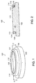
- the mandrel 100 generally includes a base 102 and a graphite ring 104.
- the base 102 comprises a titanium nitride (TiN) coated molybdenum (Mo) substrate.
- the thickness of the TiN coating is preferably in the 0.2 to 2 microns range.
- the TiN coated Mo substrate has a stepped solid cylindrical shape with a central plateau 106 and a shoulder 108.
- the central plateau 106 further includes a side wall or flank 110 having a height of approximately 0.250" (6 mm), and a circular top surface 112 having a diameter of approximately 3-4.5" (75-113 mm).
- the 90° corner 113 formed between the flank 110 and the top surface 112 is broken prior to the base being coated with TiN; i.e., the sharp edge is removed in order to expedite placement of the graphite ring 104 around the central plateau 106.
- the graphite ring 104 has an upper surface 114, a lower surface 116, an inner surface 118, and an outer surface 120.
- graphite ring is coated with silicon carbide base paint on its exposed surfaces (upper surface 114 and outer surface 120) for protection in the deposition environment.
- the height of the graphite ring 104 is preferably approximately 0.251" (6 mm); i.e., 0.001 inches higher than the height of the side wall 110 of the plateau 106.
- the thickness of the graphite ring 104 is preferably approximately 0.150-0.750", and more preferably approximately 0.250".
- the diameter across the inner surface 118 of the graphite ring 104 is approximately 0.001-0.005" greater in diameter than the diameter of the top surface 112 of the plateau 106, and most preferably 0.001 inches greater.
- the graphite ring 104 may be placed around the plateau 106, or removed from around the plateau, when the mandrel is in a cooled state (both components at room temperature) and will be secured around the plateau by an interference fit during use due to the thermal expansion of the molybdenum and the graphite.
- the graphite ring 104 is placed around the plateau 106 of the base 102 such that the lower surface 116 of the graphite ring 104 rests upon the shoulder 108 of the base 102.
- the upper surface 114 of the graphite ring 104 is substantially coplanar (i.e., 0.001" higher) with the top surface 112 of the TiN coated molybdenum base 102.
- the top surface 112 of the plateau 106 forms a first surface for receiving a CVD diamond film, while the upper surface 114 of the graphite ring 104 forms a second surface for receiving a CVD diamond film.
- the base 102 below the shoulder 108 has a diameter of approximately 7" (175 mm) and is preferably attached to a rotating cooling device.
- a diamond film is deposited on the first and second diamond film receiving surfaces 112, 114 of the mandrel until a desired diamond film thickness is achieved.
- the mandrel 100 and the diamond film 150 (shown in hatching) are then cooled. Due to the different coefficients of thermal expansion of the diamond film, the molybdenum, and the graphite, the molybdenum tends to contract under the diamond and separate from the diamond film.
- the graphite portion 104 has increased diamond adhesion properties and, as a result, the diamond tends to crack in a controlled manner at the boundary 154 of the more adherent and less adherent portions of the mandrel. This prevents the film from shattering and results in a diamond wafer 152 which is easily removed from the mandrel and has a razor clean break around its perimeter.
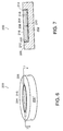
- Figures 6 and 7 show a second embodiment of the mandrel 200 of the invention.
- the mandrel 200 generally includes a graphite base 202 and a TiN coated molybdenum plug 204.
- the graphite base 202 is preferably generally cylindrical in shape, with an outer surface 205, an upper surface 206, and a central recess 208 having a floor 210 and a wall 212.
- Preferably graphite base 202 is coated with silicon carbide base paint on its exposed surfaces (outer surface 205 and upper surface 206) for protection in the deposition environment.
- the wall 212 has a height of approximately 0.250" (6 mm), and the floor 210 has a diameter of approximately 3-4.5" (75-113 mm).
- the upper surface surrounding the wall has a radial thickness of approximately 0.5".
- the 90° corner 214 formed between the upper surface 206 and the wall 212 is broken; i.e., the sharp edge is removed to expedite fitting the plug in the base.
- the plug 204 is preferably disc shaped, and has an upper surface 216, a lower surface 218, and a peripheral wall 220.
- the height of the peripheral wall 220 is preferably approximately 0.249" (6 mm); i.e., 0.001 inches lower than the height of the wall 212 forming the recess 208.
- the diameter of the plug 204 is approximately 3-4.5", and preferably at least 0.001" smaller than the diameter of the floor 210.
- the TiN coated molybdenum plug 204 may be seated in the recess when the mandrel is in a cooled state (both base 202 and plug 204 at room temperature) and will be secured within the recess by an interference fit during use due to the thermal expansion of the molybdenum and the graphite.
- the graphite base and TiN coated molybdenum plug assemble into a mandrel which has an inner upper surface with a TiN coated molybdenum central portion and a outer upper graphite surface. It will be appreciated that there may be other ways of forming a mandrel having an upper surface with a TiN coated molybdenum central surface and a surrounding graphite surface, and all other such embodiment are within the scope of this invention.
- mandrel substrates and substrate coatings have been disclosed, it will be understood that other mandrel substrates and substrate coatings can be used.
- a titanium nitride coated molybdenum mandrel substrate has been disclosed
- a titanium carbonitride coated molybdenum mandrel substrate may also be used, as well as a tungsten or titanium-zirconium-molybdenum alloy mandrel substrate.
- graphite has been described as the more diamond adhesive material, it will be appreciated that other outer “ring" materials may be used so long as the material has a greater adhesion to the diamond film than the central surface upon which the diamond wafer portion of the diamond film is formed upon.
- the graphite may have almost any ring shape, e.g., square and triangular.
- the upper surface of the graphite component is preferably generally coplanar with the upper surface of the TiN coated Mo component, it will be appreciated that the upper surface of the graphite component need not necessarily be coplanar, and that it may be angled relative to the upper surface of the TiN coated Mo component.
- the graphite component is described as having an interference fit with the Mo component when both components are heated, it will be appreciated that the graphite component may be otherwise "close fit" with the Mo component.
- a graphite ring may be thread around a plateau of an Mo base, or a plug may be key locked or screwed to a graphite base. Any manner of holding the graphite component in relation to the Mo component during diamond film deposition shall be considered a "close fit" for purposes of the claims.
- particular configurations have been disclosed in reference to the dimensions of the two components of the mandrel, it will be appreciated that other configurations could be used as well. It will therefore be appreciated by those skilled in the art that yet other modifications could be made to the provided invention without deviating from its spirit and scope as so claimed.
Landscapes
- Chemical & Material Sciences (AREA)
- Engineering & Computer Science (AREA)
- Materials Engineering (AREA)
- Metallurgy (AREA)
- Organic Chemistry (AREA)
- Crystallography & Structural Chemistry (AREA)
- Chemical Kinetics & Catalysis (AREA)
- General Chemical & Material Sciences (AREA)
- Mechanical Engineering (AREA)
- Chemical Vapour Deposition (AREA)
- Crystals, And After-Treatments Of Crystals (AREA)
Applications Claiming Priority (2)
| Application Number | Priority Date | Filing Date | Title |
|---|---|---|---|
| US96391997A | 1997-11-04 | 1997-11-04 | |
| US963919 | 1997-11-04 |
Publications (1)
| Publication Number | Publication Date |
|---|---|
| EP0916745A1 true EP0916745A1 (fr) | 1999-05-19 |
Family
ID=25507900
Family Applications (1)
| Application Number | Title | Priority Date | Filing Date |
|---|---|---|---|
| EP98203644A Withdrawn EP0916745A1 (fr) | 1997-11-04 | 1998-10-28 | Mandrin en deux parties avec bague en graphite pour le dépÔt de diamant |
Country Status (3)
| Country | Link |
|---|---|
| EP (1) | EP0916745A1 (fr) |
| JP (1) | JPH11263698A (fr) |
| CA (1) | CA2247818A1 (fr) |
Cited By (1)
| Publication number | Priority date | Publication date | Assignee | Title |
|---|---|---|---|---|
| CN106367727A (zh) * | 2016-09-06 | 2017-02-01 | 武汉工程大学 | 一种利用掩膜法制备带自支撑框架的金刚石真空窗口的方法 |
Families Citing this family (1)
| Publication number | Priority date | Publication date | Assignee | Title |
|---|---|---|---|---|
| CN113151801B (zh) * | 2021-03-03 | 2022-12-27 | 电子科技大学 | 一种自支撑悬浮碳膜制备方法 |
Citations (5)
| Publication number | Priority date | Publication date | Assignee | Title |
|---|---|---|---|---|
| EP0613963A1 (fr) * | 1993-03-05 | 1994-09-07 | General Electric Company | Production d'articles en diamant CVD sans fissures |
| EP0636706A2 (fr) * | 1993-07-26 | 1995-02-01 | General Electric Company | Appareillage pour le dépôt chimique en phase vapeur du diamant comportant des porte-substrats en graphite |
| EP0693573A1 (fr) * | 1994-07-18 | 1996-01-24 | Saint-Gobain/Norton Industrial Ceramics Corporation | Production d'un film diamant |
| EP0727507A2 (fr) * | 1995-02-15 | 1996-08-21 | Saint-Gobain/Norton Industrial Ceramics Corporation | Dispositif et procédé pour la fabrication des lames de diamant |
| EP0751237A1 (fr) * | 1995-06-07 | 1997-01-02 | Saint-Gobain/Norton Industrial Ceramics Corporation | Substrat segmenté pour la déposition du diamant par le procédé arc-jet |
-
1998
- 1998-09-25 CA CA002247818A patent/CA2247818A1/fr not_active Abandoned
- 1998-10-28 EP EP98203644A patent/EP0916745A1/fr not_active Withdrawn
- 1998-11-04 JP JP10313258A patent/JPH11263698A/ja active Pending
Patent Citations (5)
| Publication number | Priority date | Publication date | Assignee | Title |
|---|---|---|---|---|
| EP0613963A1 (fr) * | 1993-03-05 | 1994-09-07 | General Electric Company | Production d'articles en diamant CVD sans fissures |
| EP0636706A2 (fr) * | 1993-07-26 | 1995-02-01 | General Electric Company | Appareillage pour le dépôt chimique en phase vapeur du diamant comportant des porte-substrats en graphite |
| EP0693573A1 (fr) * | 1994-07-18 | 1996-01-24 | Saint-Gobain/Norton Industrial Ceramics Corporation | Production d'un film diamant |
| EP0727507A2 (fr) * | 1995-02-15 | 1996-08-21 | Saint-Gobain/Norton Industrial Ceramics Corporation | Dispositif et procédé pour la fabrication des lames de diamant |
| EP0751237A1 (fr) * | 1995-06-07 | 1997-01-02 | Saint-Gobain/Norton Industrial Ceramics Corporation | Substrat segmenté pour la déposition du diamant par le procédé arc-jet |
Cited By (1)
| Publication number | Priority date | Publication date | Assignee | Title |
|---|---|---|---|---|
| CN106367727A (zh) * | 2016-09-06 | 2017-02-01 | 武汉工程大学 | 一种利用掩膜法制备带自支撑框架的金刚石真空窗口的方法 |
Also Published As
| Publication number | Publication date |
|---|---|
| CA2247818A1 (fr) | 1999-05-04 |
| JPH11263698A (ja) | 1999-09-28 |
Similar Documents
| Publication | Publication Date | Title |
|---|---|---|
| EP0614212B1 (fr) | Un porte-substrats | |
| US5514439A (en) | Wafer support fixtures for rapid thermal processing | |
| CA2108845C (fr) | Procede de fabrication de pellicule de diamant synthetique | |
| US20110163312A1 (en) | Semiconductor-on-diamond devices and methods of forming | |
| EP3162913B1 (fr) | Suscepteur et son procédé de fabrication | |
| CA2204086C (fr) | Production de film en diamant | |
| US6533869B1 (en) | Apparatus and method for making free standing diamond | |
| JP5787558B2 (ja) | セラミックス基材支持具及びセラミックス部材の製造方法 | |
| CA2177012C (fr) | Substrat segmente pour procede ameliore de deposition de diamant assiste par plasma | |
| US20040146710A1 (en) | Metallic nanowire and method of making the same | |
| JPH03274271A (ja) | ダイヤモンド薄膜コーティング部材およびダイヤモンド薄膜コーティング方法 | |
| EP1193324B1 (fr) | Méthode de production de dômes à rapport de forme élevé par dépôt en phase vapeur | |
| US5391229A (en) | Apparatus for chemical vapor deposition of diamond including graphite substrate holders | |
| CA2247818A1 (fr) | Mandrin pour depot diamantaire en deux parties avec anneau de graphite | |
| JPH06100398A (ja) | 鏡面を有するダイヤモンド膜の製造方法 | |
| Knight et al. | Interfacial phases and the adhesion of amorphous hydrogenated carbon films deposited by rf chemical vapour deposition onto (100) silicon | |
| JPH02212394A (ja) | サセプタ | |
| Goela et al. | Mandrel reusability in precision replication of ZnS conformal domes |
Legal Events
| Date | Code | Title | Description |
|---|---|---|---|
| PUAI | Public reference made under article 153(3) epc to a published international application that has entered the european phase |
Free format text: ORIGINAL CODE: 0009012 |
|
| AK | Designated contracting states |
Kind code of ref document: A1 Designated state(s): DE FR GB |
|
| AX | Request for extension of the european patent |
Free format text: AL;LT;LV;MK;RO;SI |
|
| 17P | Request for examination filed |
Effective date: 19991119 |
|
| AKX | Designation fees paid |
Free format text: DE FR GB |
|
| 17Q | First examination report despatched |
Effective date: 20010514 |
|
| STAA | Information on the status of an ep patent application or granted ep patent |
Free format text: STATUS: THE APPLICATION IS DEEMED TO BE WITHDRAWN |
|
| 18D | Application deemed to be withdrawn |
Effective date: 20011127 |