EP0916759A2 - Verfahren und Vorrichtung zum Steuern einer Flachstrickmaschine - Google Patents
Verfahren und Vorrichtung zum Steuern einer Flachstrickmaschine Download PDFInfo
- Publication number
- EP0916759A2 EP0916759A2 EP98114349A EP98114349A EP0916759A2 EP 0916759 A2 EP0916759 A2 EP 0916759A2 EP 98114349 A EP98114349 A EP 98114349A EP 98114349 A EP98114349 A EP 98114349A EP 0916759 A2 EP0916759 A2 EP 0916759A2
- Authority
- EP
- European Patent Office
- Prior art keywords
- knitting
- motor
- needle
- reference position
- knitting member
- Prior art date
- Legal status (The legal status is an assumption and is not a legal conclusion. Google has not performed a legal analysis and makes no representation as to the accuracy of the status listed.)
- Withdrawn
Links
Images





Classifications
-
- D—TEXTILES; PAPER
- D04—BRAIDING; LACE-MAKING; KNITTING; TRIMMINGS; NON-WOVEN FABRICS
- D04B—KNITTING
- D04B15/00—Details of, or auxiliary devices incorporated in, weft knitting machines, restricted to machines of this kind
- D04B15/38—Devices for supplying, feeding, or guiding threads to needles
- D04B15/54—Thread guides
- D04B15/56—Thread guides for flat-bed knitting machines
-
- D—TEXTILES; PAPER
- D04—BRAIDING; LACE-MAKING; KNITTING; TRIMMINGS; NON-WOVEN FABRICS
- D04B—KNITTING
- D04B15/00—Details of, or auxiliary devices incorporated in, weft knitting machines, restricted to machines of this kind
- D04B15/66—Devices for determining or controlling patterns ; Program-control arrangements
-
- D—TEXTILES; PAPER
- D04—BRAIDING; LACE-MAKING; KNITTING; TRIMMINGS; NON-WOVEN FABRICS
- D04B—KNITTING
- D04B15/00—Details of, or auxiliary devices incorporated in, weft knitting machines, restricted to machines of this kind
- D04B15/94—Driving-gear not otherwise provided for
- D04B15/96—Driving-gear not otherwise provided for in flat-bed knitting machines
-
- D—TEXTILES; PAPER
- D04—BRAIDING; LACE-MAKING; KNITTING; TRIMMINGS; NON-WOVEN FABRICS
- D04B—KNITTING
- D04B35/00—Details of, or auxiliary devices incorporated in, knitting machines, not otherwise provided for
- D04B35/10—Indicating, warning, or safety devices, e.g. stop motions
- D04B35/18—Indicating, warning, or safety devices, e.g. stop motions responsive to breakage, misplacement, or malfunctioning of knitting instruments
Definitions
- This invention relates to a controlling method and apparatus for a flat knitting machine which knits while controlling the position of a knitting member such as a knitting needle or a yarn feeder by means of a motor for exclusive use.
- a flat knitting machine which performs knitting operation while the positions of knitting members are controlled by means of motors for exclusive use is disclosed in Japanese Patent Appln. Publication No. 1-12855.
- the positions of the knitting members are controlled by detecting the operation positions of the knitting members themselves or of the corresponding motors.
- Fly waste is waste of cotton produced from yarns used and accumulates on the moving paths of the knitting members as the time of use of the flat knitting machine elapses. Damage to the knitting members arises particularly when knitting needles do not move correctly. Displacement in detected position arises from a temporary lack of a detection signal in the form of pulses (an encoder signal), failure in power transmission (displacement in meshing engagement between a timing belt and a pulley arising from a slack of the belt) or the like.
- a controlling method for a flat knitting machine which includes a motor for driving a knitting member, a detector for outputting a signal corresponding to a moving amount of the motor, a position control section for receiving an output signal of the detector and driving the motor to control a position of the knitting member in response to a moving amount of the motor from a reference position.
- the controlling method comprises the steps of positioning, prior to starting of knitting, the knitting member with respect to a position setting member arranged on a moving path of the knitting member, determining, in this condition, the reference position based on an operation position of the motor, performing, after starting of knitting, the positioning again and detecting an actual moving amount of the motor from the reference position, and determining a variation between the positions of the knitting member with respect to the reference position prior to and after the starting of knitting based on a result of the detection of the moving amount.
- a controlling apparatus for a flat knitting machine comprising a motor for driving a knitting member, a detector for outputting a signal corresponding to a moving amount of the motor, a position control section for receiving an output signal of the detector and driving the motor to control a position of the knitting member in response to a moving amount of the motor from a reference position, and a position setting member arranged on a moving path of the knitting member.
- the position control section performs, prior to starting of knitting, positioning of the knitting member with respect to the position setting member, determines, in this condition, the reference position based on an operation position of the motor, performs, after starting of knitting, the positioning again and calculates an actual moving amount of the motor from the reference position, and then determines a variation between the positions of the knitting member with respect to the reference position prior to and after the starting of knitting based on a result of the detection of the moving amount.
- the positioning of the knitting member with respect to the position setting member may be performed, for example, by driving the motor until the knitting member reaches an arrangement position of the position setting member.
- the reference position may be determined as an operation position of the motor when the motor is driven by a predetermined amount from an operation position of the motor after the positioning of the knitting member is performed or as an operation position of the motor when the positioning of the knitting member is performed.
- Such a reference position may be, for example, where the knitting member is a knitting needle, a position of the motor which corresponds to a standby position (origin position) of the knitting needle.
- Knitting is started after the reference position is determined.
- the motor moves the corresponding knitting member while controlling the position of the knitting member based on the reference position. Thereafter, if accumulation of fly waste, inappropriate operation of the knitting member, displacement in detected position or the like occurs, then it appears as a variation of the position of the knitting member with respect to the reference position of the motor.
- the amount of variation of the position of the knitting member corresponding to the reference position of the motor can be obtained based on a momentum of the motor from the reference position in a positioned condition when the motor is driven, after starting of knitting, to position the knitting member with respect to the position setting member.
- the knitting member when, prior to starting of knitting, the knitting member is positioned with respect to the position setting member and the operation position of the motor in this condition is determined as a reference position, if the momentum of the motor from the reference position in a second time positioned condition reached after starting of knitting is zero, then it can be considered that the position of the knitting member with respect to the reference position of the motor exhibits no variation. However, if the momentum is outside an allowable value, then it is determined that accumulation of fly waste, inappropriate operation of the knitting member, displacement in detected position or the like has occurred, and this is informed (indicated) so that later knitting may be stopped. Consequently, expansion of deterioration of the quality of a knit fabric can be prevented.
- discrimination between normal and abnormal conditions after starting of knitting can be performed by comparing a difference between the predetermined amount and the operation amount of the motor from the reference position in a second time positioned condition with a reference position.
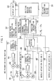
- the controlling apparatus 10 is applied to a carriageless flat knitting machine wherein a plurality of knitting needles 12 are moved back and forth not by a cam but by actuators provided individually therefor.
- a linear motor 14 is employed in the arrangement shown.
- a pulse motor, a step motor or some other motor may be employed instead.
- the carriageless flat knitting machine shown includes one or more yarn feeders 16 each for supplying a knitting yarn 18 to be knitted to the knitting needles 12. Each feeder 16 is moved back and forth by an electric motor 20.
- the controlling apparatus 10 is used to control the needle motors 14 for the knitting needles 12 and the electric motors 20 for the feeders 16.
- the momentums (actual amounts) of the needle motors 14 and the electric motors 20 are detected by encoders 22 and 24, respectively, each of which generates a momentum signal in the form of a pulse as a position signal pulse each time the corresponding motor displaces by a predetermined amount.
- a knitting machine control section 26 of the controlling apparatus 10 is connected to a knitting information setting section 28 to which various knitting information necessary for knitting is set, a display unit 30 for visibly displaying various knitting data thereon, a feeder motor control section 32 for controlling the electric motors 20, and a needle motor control section 34 for controlling the needle motors 14.
- the needle motor control section 34 includes an abnormal condition discrimination circuit 36 and a position instruction circuit 38. The abnormal condition discrimination circuit 36 and the position instruction circuit 38 are connected to the knitting machine control section 26.
- Various knitting information necessary for knitting such as a pattern to be knitted, target positions, i.e., aimed positions of the knitting needles 12, aimed positions of the feeders 16 and thrusts of them is inputted from the knitting information setting section 28 to the knitting machine control section 26 in advance.
- the knitting information is supplied from the knitting machine control section 26 to the feeder motor control section 32 and the needle motor control section 34.
- the feeder motor control section 32 is a circuit which indicates aimed positions of the electric motors 20 and hence of the feeders 16. Further, the feeder motor control section 32 receives target position signals, i.e., aimed position signals corresponding to such aimed positions from the knitting machine control section 26 and delivers the received aimed position signals as position indicating signal pulses to servo control circuits 42 in feeder driving sections 40.
- the aimed position signals are represented as momentums from origin positions of the feeders 16. If the reference positions of the electric motors 20 are adjusted to the origin positions of the feeders 16, then the aimed positions of the feeders 16 inputted from the knitting information setting section 28 can be used as they are as the aimed position signals for the electric motors 20.
- the servo control circuits 42 individually control drive circuits 44 by feedback control using the position indicating signal pulses supplied from the feeder motor control section 32 and the position signal pulses outputted from the encoders 22 to drive the electric motors 20, more particularly, to drive the electric motors 20 by momentums corresponding to the position indicating signal pulses from the reference positions, to move the corresponding feeders 16 to the aimed positions.
- the feeders 16 are moved back and forth independently of one another while the positions thereof are controlled by corresponding ones of the feeder driving sections 40 which individually include the electric motors 20 and the encoders 22.
- the position instruction circuit 38 of the needle motor control section 34 receives target position signals, i.e., aimed position signals of the needle motors 14 and hence of the corresponding knitting needles 12 from the knitting machine control section 26 and stores the received aimed position signals into a storage section 46.
- the aimed position signals stored in the storage section 46 are delivered as position indicating signal pulses to a servo control circuits 50 in a needle actuation sections 48 provided for the individual knitting needles 12.
- the needle actuation sections 48 are provided for the individual knitting needles 12.
- the aimed position signals are represented by momentums of the knitting needles 12 from the respective origin positions.
- the aimed positions of the knitting needles 12 inputted from the knitting information setting section 28 can be used as they are as the aimed position signals for the needle motors 14.
- the servo control circuits 50 individually control drive circuits 52 by feedback control using the position instruction signal pulses stored in the storage section 46 and the position signal pulses outputted from the encoders 24 to drive the needle motors 14, more particularly, to drive the needle motors 14 by momentums corresponding to the position instruction signal pulses from the reference positions of them, to cause the corresponding knitting needles 12 to perform knitting operations.
- An abnormal condition discrimination circuit and a position instruction circuit similar to the abnormal condition discrimination circuit 36 and the position instruction circuit 38 of the needle motor control section 34, respectively, may be provided in the feeder motor control section 32, and a storage section similar to the storage section 46 may be Interposed between the feeder motor control section 32 and the feeder driving sections 40.
- Knitting operation is started when a knitting starting instruction is supplied from the knitting machine control section 26 simultaneously to the feeder motor control section 32 and the needle motor control section 34.
- the feeder motor control section 32 outputs, based on predetermined knitting information, aimed position signals corresponding to target or aimed momentums from the respective positions of the electric motors 20 as position instruction signal pulses after every predetermined interval of time (for example, at intervals of 1 millisecond) to the feeder driving sections 40.
- the needle motor control section 34 writes, based on predetermined knitting information, aimed position signals corresponding to aimed momentums from the respective reference positions of the needle motors 14 as position indicating signal pulses after every predetermined interval of time (for example, at intervals of 1 millisecond) into storage areas of the storage section 46 for the individual knitting needles 12.
- the servo control circuits 42 output control signals to the drive circuits 44 based on the position indicating signal pulses supplied thereto from the feeder motor control section 32 and the position signal pulses supplied thereto from the encoders 22 so that the actual momentums (moving amounts) of the electric motors 20 may be equal to the aimed positions (target or aimed amounts).
- the servo control circuits 42 generate PWM signals based on deviations between the position indicating signal pulses and the position signal pulses as control signals after every fixed interval of time and outputs the PWM signals to the drive circuits 44. Consequently, the electric motors 20 are driven while the positions thereof are controlled by the corresponding feeder driving sections 40. Meanwhile, the feeders 16 are moved, as the corresponding electric motors 20 are driven, in the arrangement direction of the knitting needles 12 while the positions thereof are controlled to guide the respective knitting yarns 18 to knitting positions so that the knitting yarns 18 may be caught by the knitting needles 12.
- Each of the servo control circuits 50 periodically reads out the position indicating signal pulses stored in the corresponding storage area of the storage section 46 and outputs a control signal to the corresponding drive circuit 52 based on the position indicating signal pulses read out and position signal pulses supplied from the corresponding encoder 24 so that the actual momentum (moving amount) of the corresponding needle motor 14 from its reference position may be equal to the aimed position (target or aimed amount).
- the servo control circuit 50 generates a control signal based on a deviation between the position indicating signal pulses and the position signal pulses as a PWM signal after every fixed interval of time and outputs the control signal to the drive circuit 52. Consequently, the needle motor 14 is driven while the position thereof is controlled by the corresponding needle actuation section 48. Further, each of the knitting needles 12 is moved back and forth in its longitudinal direction while the position thereof is controlled as the corresponding needle motor 14 is driven.
- the controlling apparatus 10 includes, as shown in FIG. 2, a band stopper 54 serving as a position setting member for positioning a knitting needle or needles 12.
- the band stopper 54 is arranged on reciprocating moving paths of a knitting needle 12 so that it may be engaged by the knitting needle 12 when the knitting needle 12 is advanced farther than the most advanced position in knitting operation.
- the band stopper 54 may be provided for each of the knitting needles 12 or may extend over the overall knitting width so that it may be used commonly by a plurality of (preferably all) knitting needle 12 arranged on one needle bed 56. Each of the band stoppers 54 is mounted on a corresponding one of the needle beds 56.
- Each knitting needle 12 is connected to a corresponding motor by a connecting jack 58 shown in FIG. 2 so that it is moved back and forth by the corresponding motor through the connecting jack 58, and is contacted at a projection or butt 12a thereof with and positioned by the corresponding band stopper 54.
- the controlling apparatus 10 includes, as shown in FIGS. 3 and 4, for each feeder 16, a proximity sensor 60 and a dog (proximity member) 62 which serve as a position setting member for positioning the feeder 16.
- Each feeder 16 is incorporated in a yarn supply apparatus such that it supplies a knitting yarn to a knitting location from above.
- the yarn supply apparatus are supported on a common rail 64, which is assembled on a frame of the flat knitting machine so as to extend in the horizontal direction, for back and forth movement in a longitudinal direction of the rail 64.
- Each yarn supply apparatus includes a traveling member 68 supported on the rail 64 for back and forth movement in the longitudinal direction of the rail 64 by means of a plurality of rollers 66, a stay 70 extending from the traveling member 68, and a connection member 74 which connects the traveling member 68 to a timing belt 72.
- the rail 64 has guide grooves for receiving part of the rollers 66 therein.
- the electric motors 20 are mounted on the frame of the knitting machine and have output shafts on which timing pulleys (not shown) engaged with timing belts 72 are mounted.
- the timing belts 72 engaged with timing pulleys 76 mounted for rotations at locations spaced from the electric motors 20 in the longitudinal direction of the rail 64. Slackening of each of the timing belts 72 is prevented by a pair of tension rollers 78.
- the proximity sensors 60 are mounted at left side end portion of the rail 64, and the dogs 62 are mounted on the traveling members 68 or the stays 70 of each of the feeders 16. As the traveling member 68 and the stay 70 are moved by driving of the corresponding motor 20, also the feeder 16 and the dog 62 are moved. When the dog 62 comes to a position opposing the proximity sensors 60, the dog 62 is detected by the sensor 60. Accordingly, each feeder 16 is positioned as the proximity sensor 60 detects the dog 62.
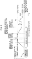
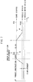
- FIGS. 5-8 illustrate a positioning step of a knitting needle 12, a determination step of a reference position of the knitting needle 12 and a calculation step of a variation of the position of the knitting needle 12 corresponding to the reference position of the corresponding needle motor 14.
- the steps mentioned above are performed for each knitting needle 12 by the corresponding needle actuation section 48 in response to an instruction from the knitting machine control section 26.
- a commutator adjustment step for all of the knitting needles 12 and the needle motors 14 is performed simultaneously.
- This commutator adjustment is performed by moving each needle motor 14 stepwise in a retracting direction so that the movement of a movable element of the needle motor 14 In the retracting direction may be stopped by a stopper not shown provided in the inside of the needle motor 14 up to an origin position of the needle motor 14.
- each knitting needle 12 is performed by operating the corresponding needle motor 14 until it reaches a position at which a motion (movement or displacement) of the needle motor 14 in one direction is stopped by the corresponding band stopper 54 and then keeping the needle motor 14 in this condition for a predetermined time.
- the power supplied to the needle motor 14 is first kept for a predetermined time at a value with which the needle motor 14 generates a thrust higher than that in knitting (for example, a thrust of 100 %) and then kept at a lower value (for example, a value with which a thrust of 12.5 % is generated by the needle motor 14) for another predetermined time.
- the knitting needle 12 By supplying power to the needle motor 14 in such a manner as described above, the knitting needle 12 is first advanced by a high thrust, and then, as the butt 12a of the knitting needle 12 is contacted with the band stopper 54, the knitting needle 12 is kept In this condition for a predetermined time, whereafter it is subjected to a comparatively low force.
- the knitting needle 12 Since the knitting needle 12 is first advanced by a high thrust as described above, it can be contacted with certainty with the band stopper 54. Further, since the knitting needle 12 is thereafter subjected to a comparatively low force, otherwise possible deformation of the band stopper 54 where a large number of knitting needles are contacted with the same can be eliminated. As a result, the knitting needle 12 and the needle motor 14 are positioned at accurate positions corresponding to the position of the band stopper 54. The position of the knitting needle 12 when the butt 12a thereof contacts the band stopper 54, that is, a correctly positioned position, is represented by "ms".
- a determination step for a reference position of the needle motor 14 is performed.
- the determination of the reference position is performed by operating the needle motor 14 by a predetermined amount in the opposite direction so that the knitting needle 12 may be retracted by a predetermined reference momentum (reference moving amount) a from the correctly positioned position "ms". Consequently, the needle motor 14 is moved to the reference position.
- the reference position in this instance is represented by "msg”.
- the reference momentum ⁇ is a fixed value and is set as a value with which, when the needle motor 14 is moved to the reference position "msg", the knitting needle 12 comes to a position coincident with a standby position (needle origin position) of the knitting needle 12 in knitting.
- the thus determined reference position is stored into the servo control circuit 50 as a standby position (needle origin position) of the knitting needle 12 in knitting when the knitting needle 12 is subjected to a thrust of 50 %.
- the positioning of the knitting needle 12 and the determination of the reference position after the commutator adjustment may be referred to as needle origin search.
- Calculation of a position variation of the knitting needle 12 that is, calculation of a variation amount between positions of the knitting needle 12 when the needle motor 14 is moved to the reference position by the servo control circuit 50 before and after knitting (including during knitting), is performed in the following manner.
- the knitting machine control section 26 drives the needle motor 14 to its reference position. Since the reference positions are stored such that the origin positions of the knitting needles coincide with aimed positions as described hereinabove, the knitting machine control section 26 outputs the needle origin positions as aimed positions to the storage section 46. Consequently, the servo control circuit 50 drives the needle motor 14 to its reference position.
- the knitting machine control section 26 operates the needle motor 14 in one direction to a position at which the operation of the needle motor 14 in the one direction is stopped, and then keeps the needle motor 14 in this condition for a predetermined time.
- the abnormal condition discrimination circuit 36 compares the actual momentum of the needle motor 14 and hence the actual momentum (moving amount) "A" of the knitting needle 12 with the reference momentum " ⁇ " of the knitting needle 12 at the time of determining the reference position "msg" to calculate the position of the knitting needle 12. Also in this instance, the thrust instruction outputted to the needle motor 14 is successively varied, for example, like 100 %, 50 %, and 12.5 %.
- the abnormal condition discrimination circuit 36 calculates the momentum "A” based on the output signal of the corresponding encoder 24, compares the thus calculated momentum "A” and the predetermined reference momentum " ⁇ " (for example, 31.0 mm) to determine a difference between them, and compares the difference between them with a predetermined reference value (for example, 0.3 mm) to discriminate whether or not the difference between them is within the reference value.
- a predetermined reference value for example, 0.3 mm
- the knitting machine control section 26 allows succeeding knitting operation.
- FIG. 7 illustrates such a displacement as described above which arises principally from a movement of a knitting needle 12, the power transmission mechanism or the like
- FIG. 8 illustrates a displacement which arises principally from fly waste accumulating on the moving path of a needle.
- the range of back and forth movement of the knitting needle is displaced from the correct range.
- the knitting machine control section 26 first corrects the reference position and then stops the knitting machine by using an abnormal condition signal outputted from the abnormal condition discrimination circuit 36 to inform (indicate) that the knitting machine is in an abnormal condition. Then, the knitting machine control section 26 displays such information (indication) on the display unit 30 together with a reason of the abnormal condition. However, if the difference between the momentums "A” and " ⁇ " remains within the allowable value, the knitting machine control section 26 does not correct the reference position and enables succeeding knitting operation.
- each of the feeders 16 is moved rightwardly from one end of its path at a high speed by the corresponding electric motor 20 first until the dog (proximity member) 62 passes the proximity sensor 60 (refer to 1 ⁇ ) and is then returned at a high speed until the dog 62 is detected again by the proximity sensor 60 (refer to 2 ⁇ ), and at a point of time when the dog 62 is detected by the proximity sensor 60, the feeder 16 is stopped. Then, the feeder 16 is moved at a low speed rightwardly from the left again (refer to 3 ⁇ ). Then, at a point of time when the dog (proximity member) 62 is detected by the proximity sensor 60 again, the feeder 16 is stopped. Consequently, the feeder 16 is positioned accurately at the position corresponding to the proximity sensor 60. Thereafter, the feeder 16 is moved leftwardly by a predetermined amount from the thus positioned position and thereafter stands by there (refer to 4 ⁇ ).
- the position corresponding to the proximity sensor 60 is determined as the origin position of the feeder 16.
- the relative distance between the positioned position and the origin position is stored as the reference momentum " ⁇ " in the abnormal condition discrimination circuit 36 and the knitting machine control section 26 in advance. It is to be noted that, in the present embodiment, the positioned position is used as the reference position, and accordingly, the reference momentum ⁇ then is set as zero.
- the feeder 16 and the electric motor 20 are positioned with respect to the proximity sensor 60, and the reference position "msg" is determined.
- the reference position "msg” is a position reached when the dog (proximity member) 62 detects the proximity sensor 60 again as the feeder is moved from the left to the right again. Knitting is performed in this condition.
- the feeder 16 and electric motor 20 are controlled so that the dog (proximity member) 62 may be moved by a predetermined distance from the reference position "msg" sensed by the proximity sensor 60.
- each of the feeders 16 is moved in a similar manner as described above so that the feeder 16 and the corresponding electric motor 20 are positioned with respect to the proximity sensor 60 again. Then, the momentum "A" from the reference position "msg" at a point of time of positioning is determined.
- the feeder motor control section 32 compares the momentum "A” and the reference momentum " ⁇ ” with each other and compares the difference between the momentums "A” and “ ⁇ ” with the reference value. If the difference between the momentums is within the reference value, then the knitting machine control section 26 corrects the reference value by making the momentum "A” zero to enable succeeding knitting operation. However, if the difference between the momentums "A” and “ ⁇ ” exceeds the reference value, then the feeder motor control section 32 informs using an abnormal condition signal outputted from the feeder motor control section 32 that the particular feeder 16 is in an abnormal condition and displays this on the display unit 30 together with a reason of the abnormal condition. Since the reference position " ⁇ " in the present embodiment is zero as described above, it is considered that the "difference between the momentums" is substantially equal to the momentum "A".
- a mechanical switch 80 which senses that the butt 12a of the knitting needle 12 is contacted therewith as shown in FIG. 10 or one or more photoelectric sensors 82 for sensing the butt 12a of the knitting needle 12 may be employed.
- a stopper for the positioning members for a feeder 16 and an electric motor 20, some other member such as a stopper may be used.
- the mechanical switch 80 shown in FIG. 10 has a detection element 81 which extends over the overall knitting width of the flat knitting machine while each of the photoelectric sensor 82 is composed of a pair of light emitting and receiving elements arranged in an opposing relationship to each other on the opposite sides of the flat knitting machine.
- Reference numeral 83 denotes an optical axis.
- a limit switch can be employed for the mechanical switches in the different apparatus described above.
- the mechanical switch 80 or the photoelectric sensor 82 is used as the position setting member, in order to determine a reference position, a sequence of operations of advancing a knitting needle 12 toward a positioning member until it is confirmed that contact of the butt 12a thereof is detected, retracting the knitting needle 12 by the reference moving amount " ⁇ " and determining the thus retracted position as a reference position should be performed for each of the knitting needles 12. If a detection signal from the position setting member is not inputted to the abnormal condition discrimination circuit 36 within a predetermined time after an instruction to advance the knitting needle 12 is issued, then it is determined that the knitting needle 12 does not operate regularly due to accumulation of fly waste, and an abnormal condition signal is outputted from the abnormal condition discrimination circuit 36 to the knitting machine control section 26.
- the stopper is provided on the left side with respect to the standby position of the feeder for the feeder not to move leftwardly as shown in FIG. 9.
- the feeder is moved leftwardly until the traveling member 68 thereof is contacted with the stopper, and either the position when the traveling member 68 is contacted with the stopper is determined as the reference position or a position rightward by the reference moving amount " ⁇ " from the position is determined as the reference position.
- a reference position corresponding to one of the traveling members can be set in the following manner.
- one of the traveling members which is positioned on the left side is contacted with the stopper while the other traveling member positioned on the right side is contacted with the traveling member positioned on the left side to effect positioning of the two traveling members.
- a similar stopper is provided also on the right-hand side end of a rail such that the left and right traveling members may correspond to the left and right stoppers, respectively, and the traveling members are contacted with the respective corresponding stoppers to effect positioning of the traveling members.
- the traveling member positioned on the right side is contacted with the stopper at the right end while the other traveling member positioned on the left side is contacted with the stopper at the left end to effect positioning of the traveling members.
- the present invention can be applied not only to a flat knitting machine of the carriageless type, but also to a flat knitting machine of the carriage type which includes a cam for moving knitting needles back and forth.
- a flat knitting machine of the carriage type if the flat knitting machine is of the type wherein a feeder is connected to and moves together with a carriage which carries the cam, then the knitting member may be the carriage, but if the knitting machine is of the type wherein a feeder and a carriage move independently of each other, then the knitting member may be the feeder and the carriage.
- positioning of a knitting member with respect to a position setting member can be performed as positioning to a value relating to the location of the position setting member such as an arrangement set position of the position setting member or a position spaced by a predetermined distance from the arrangement set position.
- the reference position for a motor can be set to a value relating to the location of the position setting member such as the arrangement set position of the position setting member or a position spaced by a predetermined distance from the arrangement set position.
Landscapes
- Engineering & Computer Science (AREA)
- Textile Engineering (AREA)
- Knitting Machines (AREA)
- Knitting Of Fabric (AREA)
Applications Claiming Priority (3)
| Application Number | Priority Date | Filing Date | Title |
|---|---|---|---|
| JP327219/97 | 1997-11-13 | ||
| JP32721997 | 1997-11-13 | ||
| JP9327219A JPH11152655A (ja) | 1997-11-13 | 1997-11-13 | 横編み機の制御方法及び装置 |
Publications (2)
| Publication Number | Publication Date |
|---|---|
| EP0916759A2 true EP0916759A2 (de) | 1999-05-19 |
| EP0916759A3 EP0916759A3 (de) | 2000-05-31 |
Family
ID=18196651
Family Applications (1)
| Application Number | Title | Priority Date | Filing Date |
|---|---|---|---|
| EP98114349A Withdrawn EP0916759A3 (de) | 1997-11-13 | 1998-07-30 | Verfahren und Vorrichtung zum Steuern einer Flachstrickmaschine |
Country Status (2)
| Country | Link |
|---|---|
| EP (1) | EP0916759A3 (de) |
| JP (1) | JPH11152655A (de) |
Cited By (7)
| Publication number | Priority date | Publication date | Assignee | Title |
|---|---|---|---|---|
| EP1061168A1 (de) * | 1999-06-16 | 2000-12-20 | Tsudakoma Kogyo Kabushiki Kaisha | Steuervorrichtung für einen Linearmotor zum Betrieb von Strickkomponenten einer Strickmaschine |
| EP1063331A1 (de) * | 1999-06-22 | 2000-12-27 | Tsudakoma Kogyo Kabushiki Kaisha | Servosteuereinheit für Flachstrickmaschine und Stricksteuervorrichtung für Flachstrickmaschine mit Servosteuereinheit |
| CN102373574A (zh) * | 2010-08-04 | 2012-03-14 | 爱吉尔电子股份公司 | 用于检测编织线上纱线意外停止的方法与装置 |
| CN102493115A (zh) * | 2011-11-29 | 2012-06-13 | 东莞华科精机有限公司 | 一种全自动起底板控制系统 |
| CN102719995A (zh) * | 2011-03-28 | 2012-10-10 | 株式会社岛精机制作所 | 横机 |
| CN109371557A (zh) * | 2018-11-21 | 2019-02-22 | 杭州之山智控技术有限公司 | 横机起底板控制系统及其方法 |
| CN110158212A (zh) * | 2019-06-10 | 2019-08-23 | 福建睿能科技股份有限公司 | 纺织控制方法以及纺织装置 |
Family Cites Families (2)
| Publication number | Priority date | Publication date | Assignee | Title |
|---|---|---|---|---|
| US4768357A (en) * | 1986-02-13 | 1988-09-06 | Asahi Kasei Kogyo Kabushiki Kaisha | Method for knitting a flat knitted fabric, a flat knitting machine and a novel flat knitted fabric knitted by said flat knitting machine |
| JPH08170253A (ja) * | 1994-12-14 | 1996-07-02 | Tsudakoma Corp | 編み機における編み針の駆動装置 |
-
1997
- 1997-11-13 JP JP9327219A patent/JPH11152655A/ja active Pending
-
1998
- 1998-07-30 EP EP98114349A patent/EP0916759A3/de not_active Withdrawn
Cited By (10)
| Publication number | Priority date | Publication date | Assignee | Title |
|---|---|---|---|---|
| EP1061168A1 (de) * | 1999-06-16 | 2000-12-20 | Tsudakoma Kogyo Kabushiki Kaisha | Steuervorrichtung für einen Linearmotor zum Betrieb von Strickkomponenten einer Strickmaschine |
| EP1063331A1 (de) * | 1999-06-22 | 2000-12-27 | Tsudakoma Kogyo Kabushiki Kaisha | Servosteuereinheit für Flachstrickmaschine und Stricksteuervorrichtung für Flachstrickmaschine mit Servosteuereinheit |
| CN102373574A (zh) * | 2010-08-04 | 2012-03-14 | 爱吉尔电子股份公司 | 用于检测编织线上纱线意外停止的方法与装置 |
| CN102373574B (zh) * | 2010-08-04 | 2014-12-31 | 爱吉尔电子股份公司 | 用于检测编织线上纱线意外停止的方法与装置 |
| CN102719995A (zh) * | 2011-03-28 | 2012-10-10 | 株式会社岛精机制作所 | 横机 |
| CN102719995B (zh) * | 2011-03-28 | 2014-12-03 | 株式会社岛精机制作所 | 横机 |
| CN102493115A (zh) * | 2011-11-29 | 2012-06-13 | 东莞华科精机有限公司 | 一种全自动起底板控制系统 |
| CN109371557A (zh) * | 2018-11-21 | 2019-02-22 | 杭州之山智控技术有限公司 | 横机起底板控制系统及其方法 |
| CN109371557B (zh) * | 2018-11-21 | 2024-02-20 | 杭州之山智控技术有限公司 | 横机起底板控制系统及其方法 |
| CN110158212A (zh) * | 2019-06-10 | 2019-08-23 | 福建睿能科技股份有限公司 | 纺织控制方法以及纺织装置 |
Also Published As
| Publication number | Publication date |
|---|---|
| JPH11152655A (ja) | 1999-06-08 |
| EP0916759A3 (de) | 2000-05-31 |
Similar Documents
| Publication | Publication Date | Title |
|---|---|---|
| EP1231310B1 (de) | Fadenliefervorrichtung | |
| EP3926084B1 (de) | Strickmaschine und fehlererkennungssystem | |
| EP0916759A2 (de) | Verfahren und Vorrichtung zum Steuern einer Flachstrickmaschine | |
| EP1548163B1 (de) | GARNZUFüHRER FüR FLACHSTRICKMASCHINE | |
| US8276263B2 (en) | Surface mounting apparatus | |
| JP2014062347A (ja) | ステッチプレッサを備えた横編機及びその制御方法 | |
| US4339933A (en) | Racking device for flat knitting machine | |
| US5862682A (en) | Method and apparatus for controlling needle driving motors in a knitting machine | |
| EP0709506B1 (de) | Vorrichtung und Verfahren zum Steuern eines Fadenführerkastens an einer Strickmaschine | |
| KR101378725B1 (ko) | 횡편기 | |
| EP1652982B1 (de) | Flachstrickmachine, sowie verfahren und vorrichtung zur entwicklung eines strickprogramms | |
| EP2246466B1 (de) | Flachstrickmaschine sowie betriebsverfahren für beweglichen träger in der flachstrickmaschine | |
| EP1498527A1 (de) | Magnetische nadelselektierung für kulierstrick- und -wirkmaschinen | |
| US20030084831A1 (en) | Sewing or embroidery machine | |
| EP1061168B1 (de) | Steuervorrichtung für einen Linearmotor zum Betrieb von Strickkomponenten einer Strickmaschine | |
| EP1908868B1 (de) | Kulierstrick- oder -wirkmaschine mit maschenpresser und verfahren zur steuerung derselben | |
| JP4415197B2 (ja) | アイ金具縫い付けパターンの自動切替方法 | |
| JPH09217248A (ja) | 織機における緯糸選択装置 | |
| JPH06158490A (ja) | 編成針の異常停止方法 | |
| JP2002079495A (ja) | 畳表の位置ずれ検知機構及び位置ずれ補正装置 | |
| JPH11152659A (ja) | 横編み機の制御装置 |
Legal Events
| Date | Code | Title | Description |
|---|---|---|---|
| PUAI | Public reference made under article 153(3) epc to a published international application that has entered the european phase |
Free format text: ORIGINAL CODE: 0009012 |
|
| AK | Designated contracting states |
Kind code of ref document: A2 Designated state(s): DE GB IT |
|
| AX | Request for extension of the european patent |
Free format text: AL;LT;LV;MK;RO;SI |
|
| PUAL | Search report despatched |
Free format text: ORIGINAL CODE: 0009013 |
|
| AK | Designated contracting states |
Kind code of ref document: A3 Designated state(s): AT BE CH CY DE DK ES FI FR GB GR IE IT LI LU MC NL PT SE |
|
| AX | Request for extension of the european patent |
Free format text: AL;LT;LV;MK;RO;SI |
|
| 17P | Request for examination filed |
Effective date: 20000912 |
|
| AKX | Designation fees paid |
Free format text: DE GB IT |
|
| STAA | Information on the status of an ep patent application or granted ep patent |
Free format text: STATUS: THE APPLICATION HAS BEEN WITHDRAWN |
|
| 17Q | First examination report despatched |
Effective date: 20020730 |
|
| 18W | Application withdrawn |
Withdrawal date: 20020821 |