EP0916836A2 - Dispositif d'admission de vapeur à l'air d'admission d'un moteur à combustion - Google Patents
Dispositif d'admission de vapeur à l'air d'admission d'un moteur à combustion Download PDFInfo
- Publication number
- EP0916836A2 EP0916836A2 EP98121359A EP98121359A EP0916836A2 EP 0916836 A2 EP0916836 A2 EP 0916836A2 EP 98121359 A EP98121359 A EP 98121359A EP 98121359 A EP98121359 A EP 98121359A EP 0916836 A2 EP0916836 A2 EP 0916836A2
- Authority
- EP
- European Patent Office
- Prior art keywords
- humidifier
- liquid
- intake air
- container
- air
- Prior art date
- Legal status (The legal status is an assumption and is not a legal conclusion. Google has not performed a legal analysis and makes no representation as to the accuracy of the status listed.)
- Granted
Links
- 238000002485 combustion reaction Methods 0.000 title claims description 16
- 239000007788 liquid Substances 0.000 claims abstract description 46
- 238000012856 packing Methods 0.000 claims description 21
- 239000007921 spray Substances 0.000 claims description 3
- 230000006698 induction Effects 0.000 abstract 1
- XLYOFNOQVPJJNP-UHFFFAOYSA-N water Substances O XLYOFNOQVPJJNP-UHFFFAOYSA-N 0.000 description 31
- 238000001704 evaporation Methods 0.000 description 11
- 230000008020 evaporation Effects 0.000 description 11
- 239000007789 gas Substances 0.000 description 7
- 239000000498 cooling water Substances 0.000 description 6
- 239000003595 mist Substances 0.000 description 6
- 238000010276 construction Methods 0.000 description 4
- MWUXSHHQAYIFBG-UHFFFAOYSA-N Nitric oxide Chemical compound O=[N] MWUXSHHQAYIFBG-UHFFFAOYSA-N 0.000 description 3
- 238000013461 design Methods 0.000 description 3
- 239000000446 fuel Substances 0.000 description 3
- 230000015572 biosynthetic process Effects 0.000 description 2
- 238000000034 method Methods 0.000 description 2
- 239000000203 mixture Substances 0.000 description 2
- 230000006866 deterioration Effects 0.000 description 1
- 238000011161 development Methods 0.000 description 1
- 230000002349 favourable effect Effects 0.000 description 1
- 230000005484 gravity Effects 0.000 description 1
- 239000000463 material Substances 0.000 description 1
- 238000012549 training Methods 0.000 description 1
Images

Classifications
-
- F—MECHANICAL ENGINEERING; LIGHTING; HEATING; WEAPONS; BLASTING
- F02—COMBUSTION ENGINES; HOT-GAS OR COMBUSTION-PRODUCT ENGINE PLANTS
- F02M—SUPPLYING COMBUSTION ENGINES IN GENERAL WITH COMBUSTIBLE MIXTURES OR CONSTITUENTS THEREOF
- F02M25/00—Engine-pertinent apparatus for adding non-fuel substances or small quantities of secondary fuel to combustion-air, main fuel or fuel-air mixture
- F02M25/022—Adding fuel and water emulsion, water or steam
- F02M25/032—Producing and adding steam
- F02M25/035—Producing and adding steam into the charge intakes
-
- Y—GENERAL TAGGING OF NEW TECHNOLOGICAL DEVELOPMENTS; GENERAL TAGGING OF CROSS-SECTIONAL TECHNOLOGIES SPANNING OVER SEVERAL SECTIONS OF THE IPC; TECHNICAL SUBJECTS COVERED BY FORMER USPC CROSS-REFERENCE ART COLLECTIONS [XRACs] AND DIGESTS
- Y02—TECHNOLOGIES OR APPLICATIONS FOR MITIGATION OR ADAPTATION AGAINST CLIMATE CHANGE
- Y02T—CLIMATE CHANGE MITIGATION TECHNOLOGIES RELATED TO TRANSPORTATION
- Y02T10/00—Road transport of goods or passengers
- Y02T10/10—Internal combustion engine [ICE] based vehicles
- Y02T10/12—Improving ICE efficiencies
Definitions
- the present invention relates to a device for feeding from steam to intake air, that of an internal combustion engine is supplied with a humidifier, which a first connection for supplying liquid for Humidifier and a second connection for feeding who has inlet air to the humidifier, the humidifier supplying steam to the intake air by contact of the inlet air and the liquid caused with each other while this by the humidifier pour a preheater to the first Connection of the humidifier is connected and the liquid before feeding to the humidifier preheated, and one to the second terminal of the humidifier connected compressor for compressing the intake air.
- Such a device is from WO 95/23 286 known.
- By supplying steam to the intake air is the level of nitrogen oxide emissions in an internal combustion engine drastically reduced as well as the Fuel efficiency increased.
- By direct evaporation of the liquid in the intake air obtained self-regulation as a special advantage to get the amount of steam in the intake air so that therefore no separate regulation of the amount of air in the intake air is required.
- the preheater is either to the cooling water or exhaust gases from the internal combustion engine connected to those in the cooling water or exhaust gases transferring stuck energy to the liquid.
- the humidifier in the known As for the device, it is a humidification tower trained the intake air and liquid in opposite directions, i.e. countercurrent, flow through, the liquid at the top and the Inlet air introduced into the humidification tower at the lower end become.
- the liquid is fed through a nozzle in the humidification tower dispersed into a mist, which by the Humidification tower falls down and through it the humidification tower compressed and thus heated intake air flows.
- Part of the Moisture evaporates and accompanies the intake air from the Humidification tower into the combustion chamber of the Internal combustion engine, for example with a diesel engine Turbocharger.
- Evaporation of the liquid in a gas mixture this way has the advantage of being essential lower temperatures occurs than in the case in which there is only water. If a strong evaporation occurs at a relatively low temperature it is possible to lower energy for the evaporation process Use stage, for example from the cooling water and / or the exhaust gases from the internal combustion engine.
- the moistening device is in the known device as a humidification tower, i.e. standing container, educated.
- This design of the humidifier is particularly suitable for guiding the intake air and the liquid in countercurrent.
- Such Construction of the humidifier can sometimes lead to space problems, especially in confined spaces, such as those found on ships are.
- the invention has for its object a device to create the specified type in relation to their height dimensions builds particularly compact.
- the humidifier is designed as a horizontal container and from the intake air and the liquid in cross flow and / or Direct current is flowed through.
- the space problems shown above are eliminated. According to the invention it was found that a such lying construction for a counterflow of the Liquid and intake air are only suitable to a limited extent, since here a relatively poor efficiency in terms of the steam generation results. This is understandable since a horizontal construction with a counter-current guide the liquid parallel to the longitudinal axis of the lying container is carried out, however, by gravity relative quickly sinks to the bottom of the container so that only one short contact distance between liquid and inlet air is available. To this relatively low efficiency to avoid steam generation, the invention proposes Solution also before that the lying container of the Inlet air and the liquid in cross flow and / or Direct current is flowed through.
- cross flow it is meant that liquid and intake air meet at an angle that is preferably 90 °, but also deviate therefrom can and for example in a range between 45 ° and 135 ° with respect to the flow direction of the inlet air can, if there is a horizontal flow through the container is assumed.
- the flow direction can also the intake air slightly from the horizontal differ.
- direct current it is meant that intake air and liquid the container essentially parallel to each other flow through, with deviations from parallelism are possible, for example up to an angle of 45 ° to the direction of flow of the intake air.
- the humidification device has at least one connected to the first port Nozzle for distributing the liquid in the container.
- This nozzle is, depending on the flow direction (cross flow or Counterflow), in the upper area or in the front area (Entry area) of the lying container.
- the Liquid is atomized into a mist using the nozzle, which falls down, with the intake air in Contact occurs and collected on the bottom of the humidifier becomes. From here it can be accessed via a line be returned to a liquid tank from which the Liquid is also removed.
- the container expediently in a lying construction has a relatively large length, it has turned out to be special proved to be favorable when the liquid is carried in cross flow, several nozzles in the upper part of the tank To arrange the flow direction of the inlet air one behind the other, so that the intake air in on its way through the container appropriate liquid sections always new liquid is fed. In this way, a particularly large one Portion of the liquid to be evaporated.
- the moistening device has at least one packing block having. This allows the humidification performance further increase. Suitable packing materials are known and need not be listed in detail here become.
- the container can optionally be equipped with a droplet separator be equipped, expediently in the downstream area of the container and after the packing blocks, if there are such.
- the liquid used is preferably to water so that the intake air of the internal combustion engine Steam is supplied.
- any desired and suitable other liquid be evaporated.
- FIG. 1 shows an internal combustion engine 1 with six cylinders 2.
- the internal combustion engine is a diesel engine with turbocharger.
- the turbocharger comprises a turbine 3, to the exhaust side of the engine 1 via an exhaust pipe 4 is connected.
- the turbine stands over a shaft 5 with a compressor 6 in connection and drives this to the engine 1 on the intake side thereof to compress a first air line 7 supplied air.
- a humidifier 8 arranged, which serves water vapor to the intake air before this via a second Air line 9 is fed to the engine.
- the steam is made up of water from a tank 10, which has a heat exchanger 11 of the humidifying device 8 is generated. In the heat exchanger 11, the water is replaced by the cooling water of the engine through a line 12 through the heat exchanger 11 circulates, heated.
- connection for the inlet air line coming from the compressor 6 7. Compressed and heated via this connection Intake air introduced into the container so that it this approximately horizontally and parallel to its longitudinal axis flows through.
- the non-evaporated water part collects at the bottom of the Container and is there via a line 13 to a tank 10 dissipated. From this tank, the water becomes a heat exchanger 11 out.
- the device works in the following way:
- the intake air is in the compressor 6, which is on the shaft 5th is driven by the turbine 3, which in turn by the Exhausting the engine 1 is driven, compressed.
- the compressed and thus heated inlet air is shown in FIG. 1 inserted from the left into the moistening device 8 and flows through it in the horizontal direction. Penetrates it the intended packing blocks 18 and is about water accumulated at the bottom of the humidifier 8 guided. Water is taken from the tank 10 and over the Heat exchanger 11 in the upper part of the humidifier 8 out where it on the three nozzles 17 on the Packing blocks 18 is sprayed. During the water falls through the packing blocks 18, it flows through which the packing blocks flow horizontally Intake air.
- Fuel the engine 1 via a Fuel line 14 is supplied. Furthermore, the engine connected to a generator 15.
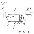
- Figure 2 shows a further embodiment of the invention Device that differs from the device of the figure 1 only by a differently designed humidification device 8 differs. In Figure 2 is therefore only a part of the overall device shown the humidifier 8th concerns.
- the moistening device is also in the embodiment of FIG 8 designed as a horizontal container.
- the humidifier container 8 of the compressed and heated intake air and flows through water in direct current.
- both media at the left end in Figure 2 of the container inserted into this. This is done via the Heat exchanger 11 supplied heated water via line 16 and is connected to one in the area the container end wall arranged nozzle 17, in which the water is distributed as a spray.
- This spray mist sinks below, however, is from the inflowing inlet air swept away.
- a Part of the water evaporates and flows with the inlet air by means of a droplet separator arranged downstream in the container 19.
Landscapes
- Engineering & Computer Science (AREA)
- Chemical & Material Sciences (AREA)
- Combustion & Propulsion (AREA)
- Mechanical Engineering (AREA)
- General Engineering & Computer Science (AREA)
- Air Humidification (AREA)
- Nozzles (AREA)
- Lubrication Details And Ventilation Of Internal Combustion Engines (AREA)
- Supercharger (AREA)
- Exhaust-Gas Circulating Devices (AREA)
- Spray-Type Burners (AREA)
Priority Applications (1)
| Application Number | Priority Date | Filing Date | Title |
|---|---|---|---|
| DK98121359T DK0916836T3 (da) | 1997-11-13 | 1998-11-10 | Indretning til tilförsel af damp til en forbrændingsmaskines indlöbsluft |
Applications Claiming Priority (2)
| Application Number | Priority Date | Filing Date | Title |
|---|---|---|---|
| DE19750181A DE19750181C2 (de) | 1997-11-13 | 1997-11-13 | Vorrichtung zur Zuführung von Dampf zur Einlaßluft einer Brennkraftmaschine |
| DE19750181 | 1997-11-13 |
Publications (3)
| Publication Number | Publication Date |
|---|---|
| EP0916836A2 true EP0916836A2 (fr) | 1999-05-19 |
| EP0916836A3 EP0916836A3 (fr) | 2000-03-08 |
| EP0916836B1 EP0916836B1 (fr) | 2004-07-28 |
Family
ID=7848530
Family Applications (1)
| Application Number | Title | Priority Date | Filing Date |
|---|---|---|---|
| EP98121359A Expired - Lifetime EP0916836B1 (fr) | 1997-11-13 | 1998-11-10 | Dispositif d'admission de vapeur à l'air d'admission d'un moteur à combustion |
Country Status (6)
| Country | Link |
|---|---|
| EP (1) | EP0916836B1 (fr) |
| AT (1) | ATE272170T1 (fr) |
| DE (2) | DE19750181C2 (fr) |
| DK (1) | DK0916836T3 (fr) |
| ES (1) | ES2227756T3 (fr) |
| PT (1) | PT916836E (fr) |
Cited By (6)
| Publication number | Priority date | Publication date | Assignee | Title |
|---|---|---|---|---|
| EP1076169A3 (fr) * | 1999-08-12 | 2001-10-10 | Munters Euroform GmbH | Dispositif pour humidifier l'air d'admission d'un moteur à combustion turbochargé |
| EP1205659A3 (fr) * | 2000-11-03 | 2002-09-11 | Wärtsilä Technology Oy AB | Procédé de réduction des émissions NOX d'un moteur à pistons surchargé |
| WO2002075141A1 (fr) * | 2001-03-20 | 2002-09-26 | Munters Euroform Gmbh | Dispositif d'humidification de l'air d'entree d'un moteur a combustion interne comportant un turbocompresseur par prechauffage au moyen d'un circuit d'eau |
| WO2003078819A1 (fr) * | 2002-03-20 | 2003-09-25 | Wärtsilä Finland Oy | Procede visant a reduire les emissions d'oxyde d'azote (nox) dans un moteur a piston suralimente et dispositif de moteur a piston |
| WO2005031144A1 (fr) * | 2003-09-24 | 2005-04-07 | Munters Euroform Gmbh | Ensemble moteur a combustion interne comprenant un dispositif d'humidification |
| WO2005038229A1 (fr) * | 2003-10-15 | 2005-04-28 | Wärtsilä Finland Oy | Procede de reduction des emissions d'oxyde d'azote (nox) d'un moteur a piston suralimente et dispositif de moteur a piston |
Families Citing this family (3)
| Publication number | Priority date | Publication date | Assignee | Title |
|---|---|---|---|---|
| DE10204181C1 (de) * | 2002-02-01 | 2003-10-09 | Man B & W Diesel Ag | Kolbenbrennkraftmaschine |
| FI118136B (fi) * | 2002-04-19 | 2007-07-13 | Marioff Corp Oy | Suihkutusmenetelmä ja -laitteisto |
| DE102011005595A1 (de) * | 2011-03-16 | 2012-09-20 | Bayerische Motoren Werke Aktiengesellschaft | Verfahren zur Nutzung von durch Betrieb einer Fahrzeugklimaanlage entstehendem Kondenswasser, Kraftfahrzeug sowie Fahrzeugkühler |
Citations (1)
| Publication number | Priority date | Publication date | Assignee | Title |
|---|---|---|---|---|
| WO1995023286A1 (fr) | 1994-02-25 | 1995-08-31 | Rosen Per | Procede et dispositif d'alimentation en vapeur de l'air d'admission d'un moteur a combustion interne |
Family Cites Families (8)
| Publication number | Priority date | Publication date | Assignee | Title |
|---|---|---|---|---|
| DE570904C (de) * | 1929-08-04 | 1933-02-22 | Gustav Schlick | Verfahren zur Bildung eines Gemisches von Luft, fein zerstaeubtem Brennstoff und Wasser |
| ES122183A1 (es) * | 1930-03-25 | 1931-04-16 | Albert Kurt | PROCEDIMIENTO PARA EL SERVICIO DE MOTORES DE COMBUSTIoN |
| US1854607A (en) * | 1930-05-15 | 1932-04-19 | Andrews Albert | Engine-cooling and supercharging means |
| DE2738807A1 (de) * | 1977-08-29 | 1979-03-15 | Henry C Linder | Verfahren und vorrichtung zur verarbeitung von brennstoff bei einer brennkraftmaschine |
| DE3339759A1 (de) * | 1983-11-03 | 1985-05-15 | Franz X. 6200 Wiesbaden Wittek | Verfahren und aufbereitungsanlage zum erzeugen eines zuendfaehigen kraftstoff/luft-gemisches fuer verbrennungskraftmaschinen |
| US4960080A (en) * | 1989-02-28 | 1990-10-02 | Cummins Engine Company, Inc. | Pollution control apparatus and method for a turbodiesel motor-generator set |
| DK170217B1 (da) * | 1993-06-04 | 1995-06-26 | Man B & W Diesel Gmbh | Stor trykladet forbrændingsmotor og fremgangsmåde til drift af en køler til afkøling af en sådan motors indsugningsluft. |
| DE19538067A1 (de) * | 1995-10-13 | 1997-04-17 | Erdgas En Systeme Gmbh | Stationäre Brennkraftmaschine und Verfahren zu ihrem Betreiben |
-
1997
- 1997-11-13 DE DE19750181A patent/DE19750181C2/de not_active Expired - Lifetime
-
1998
- 1998-11-10 DE DE59811711T patent/DE59811711D1/de not_active Expired - Fee Related
- 1998-11-10 DK DK98121359T patent/DK0916836T3/da active
- 1998-11-10 AT AT98121359T patent/ATE272170T1/de active
- 1998-11-10 PT PT98121359T patent/PT916836E/pt unknown
- 1998-11-10 EP EP98121359A patent/EP0916836B1/fr not_active Expired - Lifetime
- 1998-11-10 ES ES98121359T patent/ES2227756T3/es not_active Expired - Lifetime
Patent Citations (1)
| Publication number | Priority date | Publication date | Assignee | Title |
|---|---|---|---|---|
| WO1995023286A1 (fr) | 1994-02-25 | 1995-08-31 | Rosen Per | Procede et dispositif d'alimentation en vapeur de l'air d'admission d'un moteur a combustion interne |
Cited By (10)
| Publication number | Priority date | Publication date | Assignee | Title |
|---|---|---|---|---|
| EP1076169A3 (fr) * | 1999-08-12 | 2001-10-10 | Munters Euroform GmbH | Dispositif pour humidifier l'air d'admission d'un moteur à combustion turbochargé |
| EP1205659A3 (fr) * | 2000-11-03 | 2002-09-11 | Wärtsilä Technology Oy AB | Procédé de réduction des émissions NOX d'un moteur à pistons surchargé |
| WO2002075141A1 (fr) * | 2001-03-20 | 2002-09-26 | Munters Euroform Gmbh | Dispositif d'humidification de l'air d'entree d'un moteur a combustion interne comportant un turbocompresseur par prechauffage au moyen d'un circuit d'eau |
| WO2003078819A1 (fr) * | 2002-03-20 | 2003-09-25 | Wärtsilä Finland Oy | Procede visant a reduire les emissions d'oxyde d'azote (nox) dans un moteur a piston suralimente et dispositif de moteur a piston |
| US7178486B2 (en) | 2002-03-20 | 2007-02-20 | Wartsila Finland Oy | Method of reducing nitrogen oxide (NOx) emissions in supercharged piston engine and piston engine arrangement |
| KR100965321B1 (ko) | 2002-03-20 | 2010-06-22 | 바르실라 핀랜드 오이 | 과급된 피스톤엔진 내의 질소산화물을 감소시키는 방법 및 피스톤엔진장치 |
| WO2005031144A1 (fr) * | 2003-09-24 | 2005-04-07 | Munters Euroform Gmbh | Ensemble moteur a combustion interne comprenant un dispositif d'humidification |
| WO2005038229A1 (fr) * | 2003-10-15 | 2005-04-28 | Wärtsilä Finland Oy | Procede de reduction des emissions d'oxyde d'azote (nox) d'un moteur a piston suralimente et dispositif de moteur a piston |
| CN100408842C (zh) * | 2003-10-15 | 2008-08-06 | 瓦特西拉芬兰有限公司 | 降低增压活塞发动机氮氧化物排放物(NOx)的方法和活塞发动机装置 |
| KR101110924B1 (ko) | 2003-10-15 | 2012-04-12 | 바르실라 핀랜드 오이 | 과급 피스톤엔진의 질소산화배출물의 저감방법 및 피스톤엔진장치 |
Also Published As
| Publication number | Publication date |
|---|---|
| PT916836E (pt) | 2004-12-31 |
| EP0916836B1 (fr) | 2004-07-28 |
| DE59811711D1 (de) | 2004-09-02 |
| ES2227756T3 (es) | 2005-04-01 |
| ATE272170T1 (de) | 2004-08-15 |
| EP0916836A3 (fr) | 2000-03-08 |
| DE19750181C2 (de) | 2000-06-21 |
| DE19750181A1 (de) | 1999-05-27 |
| DK0916836T3 (da) | 2004-12-06 |
Similar Documents
| Publication | Publication Date | Title |
|---|---|---|
| DE69516307T2 (de) | Verfahren zum zuführen von dampf zur einlassluft einer brennkraftmaschine und vorrichtung dazu | |
| DE69836910T2 (de) | Vorrichtung für eine gasturbine | |
| DE69010830T2 (de) | Dampfpumpe mit Gegenstromaustauscher für Luft und Verbrennungsprodukte ohne Zwischenfluid. | |
| DE69833500T2 (de) | Zubehör für die energiegewinnung mittels gasturbine und luftbefeuchter | |
| DE69919821T2 (de) | Vorrichtung zum verdichten eines gasförmigen mediums und systeme die eine solche vorrichtung enthalten | |
| DE2163938A1 (de) | Vorrichtung zum Verdampfen von Kraftstoff | |
| DE8204570U1 (de) | Luftgekuehlter dampfverfluessiger | |
| DE19717267A1 (de) | Verfahren zur Aufbereitung von tiefgekühltem Flüssiggas | |
| EP0916836B1 (fr) | Dispositif d'admission de vapeur à l'air d'admission d'un moteur à combustion | |
| DE60318821T2 (de) | VERFAHREN ZUR REDUZIERUNG VON STICKSTOFFOXID- (NOx-)EMISSIONEN IN AUFGELADENEN KOLBENMOTOREN UND KOLBENMOTORANORDNUNG | |
| DE3120098A1 (de) | Wassererhitzungsgeraet | |
| DE69621655T2 (de) | Verfahren und vorrichtung zum liefern von mechanischer arbeit und, wenn gewünscht, wärme in einem gasverdampfungsturbinenprozess | |
| WO2019096481A1 (fr) | Système d'humidification et système de piles à combustible muni d'un système d'humidification | |
| DE1140957B (de) | Absorptionskuehlsystem und Verfahren fuer den Betrieb desselben | |
| DE69829870T2 (de) | Vorrichtung zur kühlung von gasen | |
| DE1019861B (de) | Zusatzgeraet fuer Vergasermotore | |
| DE10204181C1 (de) | Kolbenbrennkraftmaschine | |
| DE3418699A1 (de) | Vorrichtung zur erzeugung von injektionsgas, vorzugsweise zum austreiben von erdoel aus lagerstaetten | |
| DE60300583T2 (de) | Luftzufuhrsystem für eine Brennkraftmaschine | |
| DE4303514A1 (de) | Einrichtung zur Verringerung des Schadstoffausstosses bei Kraftfahrzeugen | |
| EP0908676B1 (fr) | Procédé et dispositif pour la mise en oeuvre d'une chaudière fonctionnant aux hydrocarbures liquides ou gazeux | |
| DE2139766A1 (fr) | ||
| DE10060788A1 (de) | Verfahren und Anordnung zur Bereitstellung eines zündfähigen Arbeitsgases aus einem Kryo-Kraftstoff | |
| DE69510640T2 (de) | Kessel, der zur Beheizung eines Arbeitsströmungsmittels bestimmt ist | |
| EP0577543A1 (fr) | Procédé et installation de nettoyage de gaz d'échappement d'un gros moteur diesel |
Legal Events
| Date | Code | Title | Description |
|---|---|---|---|
| PUAI | Public reference made under article 153(3) epc to a published international application that has entered the european phase |
Free format text: ORIGINAL CODE: 0009012 |
|
| AK | Designated contracting states |
Kind code of ref document: A2 Designated state(s): AT BE CH DE DK ES FR GB IE IT LI NL PT SE |
|
| AX | Request for extension of the european patent |
Free format text: AL;LT;LV;MK;RO;SI |
|
| RIN1 | Information on inventor provided before grant (corrected) |
Inventor name: WETTERGARD, JAN Inventor name: ROSEN, PER |
|
| PUAL | Search report despatched |
Free format text: ORIGINAL CODE: 0009013 |
|
| AK | Designated contracting states |
Kind code of ref document: A3 Designated state(s): AT BE CH CY DE DK ES FI FR GB GR IE IT LI LU MC NL PT SE |
|
| AX | Request for extension of the european patent |
Free format text: AL;LT;LV;MK;RO;SI |
|
| 17P | Request for examination filed |
Effective date: 20000907 |
|
| AKX | Designation fees paid |
Free format text: AT BE CH DE DK ES FR GB IE IT LI NL PT SE |
|
| 17Q | First examination report despatched |
Effective date: 20021128 |
|
| GRAP | Despatch of communication of intention to grant a patent |
Free format text: ORIGINAL CODE: EPIDOSNIGR1 |
|
| GRAS | Grant fee paid |
Free format text: ORIGINAL CODE: EPIDOSNIGR3 |
|
| GRAA | (expected) grant |
Free format text: ORIGINAL CODE: 0009210 |
|
| RIN1 | Information on inventor provided before grant (corrected) |
Inventor name: WETTERGARD, JAN Inventor name: ROSEN, PER |
|
| AK | Designated contracting states |
Kind code of ref document: B1 Designated state(s): AT BE CH DE DK ES FR GB IE IT LI NL PT SE |
|
| REG | Reference to a national code |
Ref country code: GB Ref legal event code: FG4D Free format text: NOT ENGLISH |
|
| REG | Reference to a national code |
Ref country code: CH Ref legal event code: EP |
|
| REG | Reference to a national code |
Ref country code: IE Ref legal event code: FG4D Free format text: GERMAN |
|
| REF | Corresponds to: |
Ref document number: 59811711 Country of ref document: DE Date of ref document: 20040902 Kind code of ref document: P |
|
| REG | Reference to a national code |
Ref country code: SE Ref legal event code: TRGR |
|
| REG | Reference to a national code |
Ref country code: DK Ref legal event code: T3 |
|
| GBT | Gb: translation of ep patent filed (gb section 77(6)(a)/1977) |
Effective date: 20041203 |
|
| REG | Reference to a national code |
Ref country code: PT Ref legal event code: SC4A Free format text: AVAILABILITY OF NATIONAL TRANSLATION Effective date: 20041028 |
|
| REG | Reference to a national code |
Ref country code: CH Ref legal event code: NV Representative=s name: HEPP, WENGER & RYFFEL AG |
|
| REG | Reference to a national code |
Ref country code: ES Ref legal event code: FG2A Ref document number: 2227756 Country of ref document: ES Kind code of ref document: T3 |
|
| PG25 | Lapsed in a contracting state [announced via postgrant information from national office to epo] |
Ref country code: DE Free format text: LAPSE BECAUSE OF NON-PAYMENT OF DUE FEES Effective date: 20050601 |
|
| PLBE | No opposition filed within time limit |
Free format text: ORIGINAL CODE: 0009261 |
|
| STAA | Information on the status of an ep patent application or granted ep patent |
Free format text: STATUS: NO OPPOSITION FILED WITHIN TIME LIMIT |
|
| ET | Fr: translation filed | ||
| 26N | No opposition filed |
Effective date: 20050429 |
|
| PG25 | Lapsed in a contracting state [announced via postgrant information from national office to epo] |
Ref country code: IT Free format text: LAPSE BECAUSE OF NON-PAYMENT OF DUE FEES Effective date: 20051110 |
|
| PGRI | Patent reinstated in contracting state [announced from national office to epo] |
Ref country code: IT Effective date: 20091201 |
|
| REG | Reference to a national code |
Ref country code: FR Ref legal event code: PLFP Year of fee payment: 18 |
|
| REG | Reference to a national code |
Ref country code: FR Ref legal event code: PLFP Year of fee payment: 19 |
|
| REG | Reference to a national code |
Ref country code: FR Ref legal event code: PLFP Year of fee payment: 20 |
|
| PGFP | Annual fee paid to national office [announced via postgrant information from national office to epo] |
Ref country code: DK Payment date: 20171115 Year of fee payment: 20 Ref country code: NL Payment date: 20171115 Year of fee payment: 20 Ref country code: FR Payment date: 20171117 Year of fee payment: 20 |
|
| PGFP | Annual fee paid to national office [announced via postgrant information from national office to epo] |
Ref country code: PT Payment date: 20171103 Year of fee payment: 20 Ref country code: IT Payment date: 20171123 Year of fee payment: 20 Ref country code: AT Payment date: 20171128 Year of fee payment: 20 Ref country code: BE Payment date: 20171116 Year of fee payment: 20 Ref country code: ES Payment date: 20171201 Year of fee payment: 20 Ref country code: SE Payment date: 20171115 Year of fee payment: 20 Ref country code: GB Payment date: 20171108 Year of fee payment: 20 Ref country code: IE Payment date: 20171103 Year of fee payment: 20 |
|
| PGFP | Annual fee paid to national office [announced via postgrant information from national office to epo] |
Ref country code: CH Payment date: 20180125 Year of fee payment: 20 |
|
| REG | Reference to a national code |
Ref country code: DK Ref legal event code: EUP Effective date: 20181110 |
|
| REG | Reference to a national code |
Ref country code: NL Ref legal event code: MK Effective date: 20181109 |
|
| REG | Reference to a national code |
Ref country code: CH Ref legal event code: PL |
|
| REG | Reference to a national code |
Ref country code: GB Ref legal event code: PE20 Expiry date: 20181109 |
|
| REG | Reference to a national code |
Ref country code: BE Ref legal event code: MK Effective date: 20181110 |
|
| REG | Reference to a national code |
Ref country code: AT Ref legal event code: MK07 Ref document number: 272170 Country of ref document: AT Kind code of ref document: T Effective date: 20181110 |
|
| REG | Reference to a national code |
Ref country code: IE Ref legal event code: MK9A |
|
| REG | Reference to a national code |
Ref country code: SE Ref legal event code: EUG |
|
| PG25 | Lapsed in a contracting state [announced via postgrant information from national office to epo] |
Ref country code: IE Free format text: LAPSE BECAUSE OF EXPIRATION OF PROTECTION Effective date: 20181110 Ref country code: PT Free format text: LAPSE BECAUSE OF EXPIRATION OF PROTECTION Effective date: 20181119 |
|
| PG25 | Lapsed in a contracting state [announced via postgrant information from national office to epo] |
Ref country code: GB Free format text: LAPSE BECAUSE OF EXPIRATION OF PROTECTION Effective date: 20181109 |
|
| REG | Reference to a national code |
Ref country code: ES Ref legal event code: FD2A Effective date: 20200803 |
|
| PG25 | Lapsed in a contracting state [announced via postgrant information from national office to epo] |
Ref country code: ES Free format text: LAPSE BECAUSE OF EXPIRATION OF PROTECTION Effective date: 20181111 |