EP0916901A1 - Appareil pour réduire le tartrage pour chauffe-eau à gaz - Google Patents
Appareil pour réduire le tartrage pour chauffe-eau à gaz Download PDFInfo
- Publication number
- EP0916901A1 EP0916901A1 EP97830588A EP97830588A EP0916901A1 EP 0916901 A1 EP0916901 A1 EP 0916901A1 EP 97830588 A EP97830588 A EP 97830588A EP 97830588 A EP97830588 A EP 97830588A EP 0916901 A1 EP0916901 A1 EP 0916901A1
- Authority
- EP
- European Patent Office
- Prior art keywords
- heating water
- heat exchanger
- water
- heating
- sanitary
- Prior art date
- Legal status (The legal status is an assumption and is not a legal conclusion. Google has not performed a legal analysis and makes no representation as to the accuracy of the status listed.)
- Withdrawn
Links
- 239000008236 heating water Substances 0.000 claims abstract description 73
- XLYOFNOQVPJJNP-UHFFFAOYSA-N water Substances O XLYOFNOQVPJJNP-UHFFFAOYSA-N 0.000 claims abstract description 40
- 238000010438 heat treatment Methods 0.000 claims description 11
- 230000015572 biosynthetic process Effects 0.000 description 5
- OSGAYBCDTDRGGQ-UHFFFAOYSA-L calcium sulfate Chemical compound [Ca+2].[O-]S([O-])(=O)=O OSGAYBCDTDRGGQ-UHFFFAOYSA-L 0.000 description 2
- 239000012530 fluid Substances 0.000 description 2
- 150000003839 salts Chemical class 0.000 description 2
- 238000012546 transfer Methods 0.000 description 2
- 230000002411 adverse Effects 0.000 description 1
- -1 calcium sulphate Chemical class 0.000 description 1
- 235000011132 calcium sulphate Nutrition 0.000 description 1
- 239000001175 calcium sulphate Substances 0.000 description 1
- 239000011248 coating agent Substances 0.000 description 1
- 238000000576 coating method Methods 0.000 description 1
- 238000002485 combustion reaction Methods 0.000 description 1
- 238000011161 development Methods 0.000 description 1
- 239000003517 fume Substances 0.000 description 1
- 229910052751 metal Inorganic materials 0.000 description 1
- 239000002184 metal Substances 0.000 description 1
- 238000012986 modification Methods 0.000 description 1
- 230000004048 modification Effects 0.000 description 1
- 238000012544 monitoring process Methods 0.000 description 1
- 238000013021 overheating Methods 0.000 description 1
- 238000001556 precipitation Methods 0.000 description 1
Images

Classifications
-
- F—MECHANICAL ENGINEERING; LIGHTING; HEATING; WEAPONS; BLASTING
- F24—HEATING; RANGES; VENTILATING
- F24D—DOMESTIC- OR SPACE-HEATING SYSTEMS, e.g. CENTRAL HEATING SYSTEMS; DOMESTIC HOT-WATER SUPPLY SYSTEMS; ELEMENTS OR COMPONENTS THEREFOR
- F24D3/00—Hot-water central heating systems
- F24D3/08—Hot-water central heating systems in combination with systems for domestic hot-water supply
-
- F—MECHANICAL ENGINEERING; LIGHTING; HEATING; WEAPONS; BLASTING
- F24—HEATING; RANGES; VENTILATING
- F24D—DOMESTIC- OR SPACE-HEATING SYSTEMS, e.g. CENTRAL HEATING SYSTEMS; DOMESTIC HOT-WATER SUPPLY SYSTEMS; ELEMENTS OR COMPONENTS THEREFOR
- F24D2220/00—Components of central heating installations excluding heat sources
- F24D2220/08—Storage tanks
Definitions
- the invention generally relates to gas-fired boilers intended to be used for supplying hot water for heating and sanitary purposes. More particularly, the present invention relates to a device permitting the scale formation in said gas-fired boilers to be reduced.
- the gas-fired boilers comprise a circuit for the heating water (primary circuit) and a circuit for the sanitary water (secondary circuit) .
- Each circuit is provided with an own heat exchanger (primary heat exchanger and secondary heat exchanger).
- primary heat exchanger heat provided by the burner flame is transferred to the heating water.
- secondary heat exchanger heat is transferred from the hot heating water circulating in the primary circuit to the cold sanitary water circulating in the secondary circuit.
- the formation of scale is more likely to occur in the secondary heat exchanger.
- the conventional gas-fired boilers do not prevent a certain amount of the heating water utilized as a medium for heating the sanitary water from remaining in the secondary heat exchanger when there is no demand of sanitary water.
- the amount of hot heating water that remains at rest in the secondary heat exchanger provides an optimal condition for the development of scale on the inside of the secondary heat exchanger.
- the object of the present invention is to provide a device for reducing the scale formation in the secondary heat exchanger of gas-fired boilers for domestic purposes by preventing the heating water from flowing and remaining in the secondary heat exchanger when there is no demand of sanitary water, while permitting the heating water to be heated during a water preheating period.
- the scale reducing device for gas-fired boilers is characterized in that it comprises a pipe arranged so as to by-pass the heating water inlet and outlet pipes of the secondary heat exchanger and a valve for controlling the flow of the heating water through said pipe, said device being disposed in the primary circuit and arranged to by-pass the secondary heat exchanger so as to prevent the heating water from flowing and remaining therein when there is no demand of hot sanitary water.
- the valve controlling the flow through the pipe is an electrically operated by-pass valve under control of a manostat provided in the secondary circuit and a temperature sensor provided in the heating water storage vessel, so that said by-pass valve will be closed when there is demand of hot sanitary water and opened when said demand of sanitary water is terminated or when the temperature of the heating water is below a predetermined value.
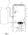
- the gas-fired boiler 10 comprises a primary circuit 11 and a secondary circuit 12, both intended to heat the water through a corresponding heat exchanger, i.e. a primary heat exchanger 13 for the heating water and a secondary heat exchanger 14 for the sanitary water.
- the primary circuit 11 is formed of a heating water supply pipe 15 departing from the primary heat exchanger 13 where the heating water is subjected to the hot combustion fumes, and a heating water return pipe 16 which leads to the primary heat exchanger 13.
- the heating water return pipe 16 embodies a circulation pump 17 for the heating water in the primary circuit 11, a safety device 18 connected to an emergency switch 18' and intended to cut off the heating water flow in the case of a malfunctioning and a three-way valve 19 for controlling the flow direction of the heating water.
- the gas-fired boiler 10 also includes a heating water storage vessel 20 which is intended to store the heating water when the latter is not to be supplied to the heating units (not shown).
- the storage vessel 20 is connected to the heating water outlet of the secondary heat exchanger 14 via an outlet pipe 21 and to the primary circuit 11 via a return pipe 22 leading to the three-way valve 19.
- the heating water inlet of secondary heat exchanger 14 is connected to the primary circuit 11 via an inlet pipe 23 which is branched off from the heating water supply pipe 15 and in which a check valve 24 is provided.
- the heating water flow can be diverted from the heating water supply pipe 15 into the secondary heat exchanger 14 via the inlet pipe 23 and therefrom into the storage vessel 20, and then returned to the heating water return pipe 16 through the return pipe 22.
- a temperature sensor 25 is included in the heating water supply pipe for sensing the temperature of the heating water from the primary heat exchanger 13.
- the secondary circuit 12 includes a sanitary hot water delivery pipe 26 departing from the sanitary water outlet of the secondary heat exchanger 14 and a sanitary cold water supply pipe 27 leading to the sanitary water inlet of said secondary heat exchanger.
- a temperature sensor 28 is located in the sanitary hot water delivery pipe 26 for monitoring the temperature of the sanitary water.
- the sanitary cold water supply pipe 27 includes a flow control device 29, typically a manostat, connected to a switch 29' and intended to control the flow of the sanitary water.
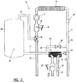
- FIG 2 there is shown a gas-fired boiler for domestic purposes provided with the scale reducing device in the primary circuit 11 according to the invention.
- the scale reducing device in the primary circuit 11 according to the invention.
- all parts corresponding to those shown in Figure 1 are identified by the same numeral characters.
- the scale reducing device comprises a by-pass pipe 30' establishing a parallel flow path for the heating water around the secondary heat exchanger 14 and a by-pass valve 30'' controlling the flow of the heating water through said by-pass pipe 30'.
- the by-pass pipe 30' is arranged so as to by-pass the heating water inlet and outlet pipes 23, 21 of the secondary heat exchanger 14.
- the heating water storage vessel 20 is provided with a temperature sensor 31 the purpose of which will be explained in the following.
- the by-pass valve 30'' of this device 30 is electrically operated in response to signals transmitted by the flow control device 29 located in the secondary circuit 12 and the temperature sensor 31 located in the heating water storage vessel 20.
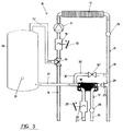
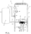
- a gas-fired boiler comprising the scale reducing device 30 of the invention has three operation modes during which the heating water and the sanitary water flows are indicated by the arrows in Figures 3, 4 and 5, respectively.
- FIG. 3 there is shown the first operation mode in which there is no demand of hot water for heating or sanitary purposes.
- the by-pass valve 30'' is open, whereas the three-way valve 19 is switched to disconnect the primary circuit 11 from the heating units (not shown) by closing the heating water return pipe 16.
- the heating water flow is so diverted from the heating water supply pipe 15 into the water storage vessel 20 via the by-pass pipe 30' and returned to the three-way valve 19 via the return pipe 22. In so doing, the heating water is heated in the primary heat exchanger 13 during the water preheating period, but does not flow through the secondary heat exchanger 14 as occurs in the conventional gas-fired boilers.
- FIG 4 there is shown the second operation mode in which there is demand of hot water for heating purposes only.
- the three-way valve 19 is switched to disconnect the secondary heat exchanger 14 from the primary circuit 11 by closing the return pipe 22.
- the heating water is supplied to the heating units (not shown) via the heating water supply pipe 15 and returns back to the primary heat exchanger 13 via the heating water return pipe 16.
- FIG. 5 shows the third operation mode in which there is also demand of hot water for sanitary purposes.
- the by-pass valve 30'' of the scale reducing device 30 is closed and the three-way valve 19 is switched to disconnect the heating units from the primary circuit 11 by closing the heating water return pipe 16.
- the flow of the heating water is diverted from the heating water supply pipe 15 into the secondary heat exchanger 14 and the storage vessel 20, and then returned to the three-way valve 19 via the return pipe 22. Since the by-pass valve 30'' is closed, the hot heating water is forced by the circulation pump 17 to flow through the secondary heat exchanger 14 where it transfers heat to the cold sanitary water entering therein.
- the by-pass valve 30'' opens and the secondary heat exchanger 14 empties so that no heating water will remain at rest therein. Then, the three-way valve 19 is switched to disconnect the secondary heat exchanger 14 from the primary circuit 11 and to connect the heating units to primary circuit 11 back again.
- the scale reducing device 30 of the present invention substantially reduces the possibility of scale formation inside the secondary heat exchanger 14 without involving expensive modifications in the conventional gas-fired boilers for domestic purposes.
Landscapes
- Engineering & Computer Science (AREA)
- Water Supply & Treatment (AREA)
- Physics & Mathematics (AREA)
- Thermal Sciences (AREA)
- Chemical & Material Sciences (AREA)
- Combustion & Propulsion (AREA)
- Mechanical Engineering (AREA)
- General Engineering & Computer Science (AREA)
- Instantaneous Water Boilers, Portable Hot-Water Supply Apparatuses, And Control Of Portable Hot-Water Supply Apparatuses (AREA)
Priority Applications (1)
| Application Number | Priority Date | Filing Date | Title |
|---|---|---|---|
| EP97830588A EP0916901A1 (fr) | 1997-11-11 | 1997-11-11 | Appareil pour réduire le tartrage pour chauffe-eau à gaz |
Applications Claiming Priority (1)
| Application Number | Priority Date | Filing Date | Title |
|---|---|---|---|
| EP97830588A EP0916901A1 (fr) | 1997-11-11 | 1997-11-11 | Appareil pour réduire le tartrage pour chauffe-eau à gaz |
Publications (1)
| Publication Number | Publication Date |
|---|---|
| EP0916901A1 true EP0916901A1 (fr) | 1999-05-19 |
Family
ID=8230851
Family Applications (1)
| Application Number | Title | Priority Date | Filing Date |
|---|---|---|---|
| EP97830588A Withdrawn EP0916901A1 (fr) | 1997-11-11 | 1997-11-11 | Appareil pour réduire le tartrage pour chauffe-eau à gaz |
Country Status (1)
| Country | Link |
|---|---|
| EP (1) | EP0916901A1 (fr) |
Cited By (6)
| Publication number | Priority date | Publication date | Assignee | Title |
|---|---|---|---|---|
| EP1026449A1 (fr) * | 1999-02-03 | 2000-08-09 | IABER S.p.A. | Chaudière avec écoulement maximal |
| EP0940636A3 (fr) * | 1998-03-06 | 2001-09-12 | Immergas S.p.A. | Chaudière et méthode pour chauffer et pour préparer de l'eau chaude sanitaire |
| EP0981031A3 (fr) * | 1998-08-18 | 2002-07-31 | ALCO Corporation of Namdong Industrial Area 156BL/10LT | Appareil pour circuler l'eau de chauffage et pour le chauffage instantané de l'eau sanitaire dans une chaudière mixte |
| EP1577615A1 (fr) * | 2004-03-17 | 2005-09-21 | Martin Sandler Systemtechnik E.K. | Procédé et dispositif pour la production de l'eau sanitaire avec un échangeur de chaleur |
| CN101289232B (zh) * | 2008-06-06 | 2012-10-03 | 淄博建龙化工有限公司 | 一种利用硫酸生产低温余热预热脱盐水的方法和装置 |
| CN107076461A (zh) * | 2014-11-19 | 2017-08-18 | 庆东纳碧安株式会社 | 具有与水管管道一体化的止回阀的锅炉 |
Citations (3)
| Publication number | Priority date | Publication date | Assignee | Title |
|---|---|---|---|---|
| US4347972A (en) * | 1979-02-27 | 1982-09-07 | Ab Ctc | Apparatus for production of hot water |
| GB2262593A (en) * | 1991-12-17 | 1993-06-23 | Inter Albion Ltd | An apparatus for and method of providing hot sanitary water |
| EP0635682A1 (fr) * | 1993-07-20 | 1995-01-25 | INTEGRA S.r.l. | Chaudière-mixte à accumulation de chaleur |
-
1997
- 1997-11-11 EP EP97830588A patent/EP0916901A1/fr not_active Withdrawn
Patent Citations (3)
| Publication number | Priority date | Publication date | Assignee | Title |
|---|---|---|---|---|
| US4347972A (en) * | 1979-02-27 | 1982-09-07 | Ab Ctc | Apparatus for production of hot water |
| GB2262593A (en) * | 1991-12-17 | 1993-06-23 | Inter Albion Ltd | An apparatus for and method of providing hot sanitary water |
| EP0635682A1 (fr) * | 1993-07-20 | 1995-01-25 | INTEGRA S.r.l. | Chaudière-mixte à accumulation de chaleur |
Cited By (7)
| Publication number | Priority date | Publication date | Assignee | Title |
|---|---|---|---|---|
| EP0940636A3 (fr) * | 1998-03-06 | 2001-09-12 | Immergas S.p.A. | Chaudière et méthode pour chauffer et pour préparer de l'eau chaude sanitaire |
| EP0981031A3 (fr) * | 1998-08-18 | 2002-07-31 | ALCO Corporation of Namdong Industrial Area 156BL/10LT | Appareil pour circuler l'eau de chauffage et pour le chauffage instantané de l'eau sanitaire dans une chaudière mixte |
| EP1026449A1 (fr) * | 1999-02-03 | 2000-08-09 | IABER S.p.A. | Chaudière avec écoulement maximal |
| EP1577615A1 (fr) * | 2004-03-17 | 2005-09-21 | Martin Sandler Systemtechnik E.K. | Procédé et dispositif pour la production de l'eau sanitaire avec un échangeur de chaleur |
| CN101289232B (zh) * | 2008-06-06 | 2012-10-03 | 淄博建龙化工有限公司 | 一种利用硫酸生产低温余热预热脱盐水的方法和装置 |
| CN107076461A (zh) * | 2014-11-19 | 2017-08-18 | 庆东纳碧安株式会社 | 具有与水管管道一体化的止回阀的锅炉 |
| CN107076461B (zh) * | 2014-11-19 | 2020-01-31 | 庆东纳碧安株式会社 | 具有与水管管道一体化的止回阀的锅炉 |
Similar Documents
| Publication | Publication Date | Title |
|---|---|---|
| US3896992A (en) | Heat recovery system for space heating and for potable water heating | |
| EP0916901A1 (fr) | Appareil pour réduire le tartrage pour chauffe-eau à gaz | |
| US8505619B2 (en) | Heat exchanger with temperature-controlled valve | |
| CN110940088A (zh) | 无水箱热水器设备、系统以及方法 | |
| JP3836526B2 (ja) | 給湯システム | |
| EP0940636B1 (fr) | Chaudière de chauffage et de préparation d'eau chaude sanitaire | |
| GB2235966A (en) | Water heating systems | |
| JP3800667B2 (ja) | 風呂装置 | |
| KR100279886B1 (ko) | 온수난방 겸용 가스보일러에서의 난방절체시 삼방변 이동 및연소제어 방법 | |
| JP3834406B2 (ja) | 一缶二水路給湯器 | |
| JP3613033B2 (ja) | 循環式給湯装置 | |
| JPH045925Y2 (fr) | ||
| JP3584454B2 (ja) | 自然循環式給湯器付風呂釜 | |
| JP4784266B2 (ja) | 給湯装置 | |
| JPH0136019Y2 (fr) | ||
| JP4602062B2 (ja) | 給湯装置 | |
| KR0140389B1 (ko) | 급탕기능이 있는 온수 난방장치 | |
| JPH0218430Y2 (fr) | ||
| JP3834421B2 (ja) | 一缶多水路型給湯機 およびその制御方法 | |
| JP3834405B2 (ja) | 一缶二水路給湯器 | |
| EP0828116A2 (fr) | Système de chauffage | |
| JP2006112648A (ja) | 給湯装置 | |
| JPH068447Y2 (ja) | 給湯用ガスブースター | |
| JPH11325600A (ja) | 温水ボイラの温度制御装置 | |
| JPH0641053Y2 (ja) | 給湯装置 |
Legal Events
| Date | Code | Title | Description |
|---|---|---|---|
| PUAI | Public reference made under article 153(3) epc to a published international application that has entered the european phase |
Free format text: ORIGINAL CODE: 0009012 |
|
| 17P | Request for examination filed |
Effective date: 19980922 |
|
| AK | Designated contracting states |
Kind code of ref document: A1 Designated state(s): AT BE CH DE DK ES FI FR GB GR IE IT LI LU MC NL PT SE |
|
| AX | Request for extension of the european patent |
Free format text: AL;LT;LV;MK;RO;SI |
|
| AKX | Designation fees paid |
Free format text: AT DE ES FR GB IT |
|
| 17Q | First examination report despatched |
Effective date: 20001208 |
|
| STAA | Information on the status of an ep patent application or granted ep patent |
Free format text: STATUS: THE APPLICATION HAS BEEN WITHDRAWN |
|
| 18W | Application withdrawn |
Withdrawal date: 20010327 |