EP0916912A2 - Radiateur - Google Patents
Radiateur Download PDFInfo
- Publication number
- EP0916912A2 EP0916912A2 EP98120684A EP98120684A EP0916912A2 EP 0916912 A2 EP0916912 A2 EP 0916912A2 EP 98120684 A EP98120684 A EP 98120684A EP 98120684 A EP98120684 A EP 98120684A EP 0916912 A2 EP0916912 A2 EP 0916912A2
- Authority
- EP
- European Patent Office
- Prior art keywords
- radiator
- valve
- heating
- connection
- riser
- Prior art date
- Legal status (The legal status is an assumption and is not a legal conclusion. Google has not performed a legal analysis and makes no representation as to the accuracy of the status listed.)
- Withdrawn
Links
Images


Classifications
-
- F—MECHANICAL ENGINEERING; LIGHTING; HEATING; WEAPONS; BLASTING
- F24—HEATING; RANGES; VENTILATING
- F24D—DOMESTIC- OR SPACE-HEATING SYSTEMS, e.g. CENTRAL HEATING SYSTEMS; DOMESTIC HOT-WATER SUPPLY SYSTEMS; ELEMENTS OR COMPONENTS THEREFOR
- F24D19/00—Details
- F24D19/02—Arrangement of mountings or supports for radiators
- F24D19/024—Functioning details of supporting means for radiators
- F24D19/0293—Radiators rotating without being demounted
-
- F—MECHANICAL ENGINEERING; LIGHTING; HEATING; WEAPONS; BLASTING
- F24—HEATING; RANGES; VENTILATING
- F24D—DOMESTIC- OR SPACE-HEATING SYSTEMS, e.g. CENTRAL HEATING SYSTEMS; DOMESTIC HOT-WATER SUPPLY SYSTEMS; ELEMENTS OR COMPONENTS THEREFOR
- F24D19/00—Details
- F24D19/0002—Means for connecting central heating radiators to circulation pipes
-
- F—MECHANICAL ENGINEERING; LIGHTING; HEATING; WEAPONS; BLASTING
- F24—HEATING; RANGES; VENTILATING
- F24D—DOMESTIC- OR SPACE-HEATING SYSTEMS, e.g. CENTRAL HEATING SYSTEMS; DOMESTIC HOT-WATER SUPPLY SYSTEMS; ELEMENTS OR COMPONENTS THEREFOR
- F24D19/00—Details
- F24D19/0002—Means for connecting central heating radiators to circulation pipes
- F24D19/0056—Supplies from the central heating system
- F24D19/0058—Supplies from the central heating system coming out the floor
- F24D19/0063—Supplies from the central heating system coming out the floor under the radiator
-
- F—MECHANICAL ENGINEERING; LIGHTING; HEATING; WEAPONS; BLASTING
- F24—HEATING; RANGES; VENTILATING
- F24D—DOMESTIC- OR SPACE-HEATING SYSTEMS, e.g. CENTRAL HEATING SYSTEMS; DOMESTIC HOT-WATER SUPPLY SYSTEMS; ELEMENTS OR COMPONENTS THEREFOR
- F24D19/00—Details
- F24D19/08—Arrangements for drainage, venting or aerating
- F24D19/082—Arrangements for drainage, venting or aerating for water heating systems
- F24D19/083—Venting arrangements
- F24D19/085—Arrangement of venting valves for central heating radiators
Definitions
- the present invention relates to a radiator for central heating systems and in particular a panel radiator for central heating systems, such as district heating systems, central heating systems or the like.
- a radiator is with a flow and a return line, with a heating line extending therebetween.
- radiators in particular panel radiators
- Such radiators are usually in the lower section of the radiator connected, the flow on an outer side edge of the radiator is led up to an upper portion of this radiator to there one heating register or two heating registers to be connected.
- Such a radiator in which the heating medium is supplied laterally above, has the disadvantage that in particular with medium and low heating outputs, a temperature drop over the length of the radiator may appear very massive.
- valve or thermostatic valve from the side of the radiator staggered, such that it is, for example, from the upper section of the radiator protrudes in its vertical extent so that the valve is easy to reach is in the design of the radiator and is less accident-prone.
- the riser can also be a vertically extending heating tube, which is attached to her the lower end is mechanically connected to the radiator, for example, fluidically however only connected to the flow of the radiator or the central heating system is.
- the valve can advantageously, for example, be centered on the top Radiators are provided.
- valve is arranged at the upper end of the radiator designed according to the invention is, it may be advantageous in the case of a panel radiator, a temperature sensor or a thermostatic head on a thermally shielded area of the Radiator to prevent the temperature sensor from being near heat radiating sections of the radiator is irritated or regulation independent depending on the temperature of a room in which the radiator is located and only of the temperature of the radiator.
- the control knob of the valve of a radiator with features according to the invention can be preferably on the upper section of the radiator, preferably on the upper cover of the Provide the radiator, the arrangement of the control knob being offset and preferred can be done at least approximately in the middle. Accordingly, a control knob of the valve can also be arranged with a tube radiator.
- the riser and / or the pipe, via the radiator at the lower section to the central heating system or district heating system is connected, can also be at least partially made of a flexible material be trained. This can be both the assembly of the radiator and subsequent renovation work or the like when the radiator is out of its standing position must be swung out in a radiator recess or the like.
- the riser or downpipe comprises for connection to the radiator a connection fitting that is attached to the riser.
- the connection fitting has at least one preferably angled by about 90 ° to the connection area of the riser Connection section to connect the heating line or a heating plate comprising this.
- this connection fitting a connection for two Should form heating plates, the connection fitting has two, preferably by at least about 90 ° exactly 90 ° angled connection areas.
- the connection fitting can also additionally with connection areas, for example for a vent valve, for the valve for regulation the flow of the heating medium through the radiator and / or other functional parts be used.
- the lower connection that is to say the return connection of the radiator, can also advantageously be used have a corresponding connection fitting.
- valve can regulate the flow of the heating medium through the radiator with features according to the invention can also be provided in a valve fitting to the Riser is connected.
- connection fitting can be used of the radiator to the riser only with a connection section for a heating plate or two opposite connection sections for two heating plates or the like be provided. If necessary, a connection section for a vent valve can also be provided be provided.
- connection fitting and the Valve fitting are combined to form a combination fitting, the valve section on the combination fitting in its installed position on the radiator, so that a control knob of the valve is preferably accessible from above.
- this combination fitting also an installation section for the ventilation device include.
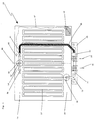
- the reference numeral 10 is generally a radiator with features according to reproduced the invention. It should be emphasized that the connection arrangement with or without a valve can also be regarded as an invention and possibly in claims can be dressed.
- the radiator 10 is supplied by a central heating system 20 supplied with heating medium.
- the used or cooled heating medium is over the Return 18 discharged.
- the inlet and the return 20, 18 are a radiator inlet 22 and a radiator-side return 24 assigned.
- the whole connection facial expression with the radiator-side flow 22, the radiator-side return 24, the connections for the radiator and possibly other components are via a mounting plate 26 summarized, which can be attached to the wall of a building.
- a riser 28 extends from the radiator supply line and extends to the upper one Section of the radiator 10 extends. There is a connection line opposite 30, via a connection area 32 to the radiator 10 or the heating register 12 a collective discharge line 16 is connected.
- the line 30 can be arranged so that it is in relation to a
- the axis of symmetry 48 is arranged on the same side as the riser 28.
- the heater 10 can be a heating plate with a heating register 12, 14, 16 as well have two heating plates, which can be designed accordingly.
- the heating medium supplied to the radiator 10 is in the illustrated embodiment fed to the heating register 12 via the distribution line 14 and beyond the heating register 12 summarized by the derivation 16 to be introduced into the return line 30 become.
- a valve 46 is arranged on the upper section 44 of the riser 28.
- This valve can both thermostatically controlled with a temperature sensor located directly there be, but it has proven to be advantageous, the actual temperature sensor 40 to be placed on a section of the radiator that is not subject to high temperatures, so that the temperature of the radiator measuring the temperature of a room in which the Radiator 10 is arranged, not falsified.
- the connection between the Temperature sensors for example a paraffin cartridge or the like, can be used via a suitable connection, for example a capillary 42 can be transferred to the valve.
- the control knob of the valve 46 should advantageously be at the upper end of the radiator 10 may be arranged. If an upper cover is provided, the adjusting knob of the Valve 46 protrude from this cover to allow adjustment.
- the control knob of the valve can be connected to the valve plate using a special adjustment mechanism be, the connection 42, for example a capillary, can influence the position of the valve plate.
- the valve 46 can preferably be arranged in such a way that it can be operated via an adjusting knob (not shown), from an existing top cover of the radiator 10 in the area 48 protrudes near or directly on the axis of symmetry 48 of the radiator 10 is operable.
- valve 46 should be housed in the radiator while it is from the outside of the radiator, whether from above or from one side or from the front, can be operated. Greater distances between the valve 46 and the control knob can be achieved by mechanical and / or hydrodynamic coupling arrangements are bridged.
- the valve 46 can both have an adjustment range over which a basic or fixed flow rate adjustment can be carried out. There is also a To provide a control section, by hand or via the thermostat section 40 Regulation can be carried out. Both functional areas can also be combined in one common geometry can be provided.
- connection fitting 50, 52 is provided for connecting the riser 28.
- the connection fitting has only one connection section 52, which extends from the body 50 of the connection fitting 52, 50.
- a vent valve 56 can be scheduled.
- the said sections can each be formed as individual components be. However, it is particularly preferred if at least some of the parts 46, 50, 52, 54 and 56 are connected to a connection fitting, which is preferably preferred for all of said parts is provided.
- the heating medium is on the flow 20, 22 inserted into the riser 28.
- the heating medium passes through the line section 44 and the valve 46 in the line connection section 54 and subsequently via the Fitting 50 and the connecting section 52 in the distributor line 14 of the radiator 10. Then the heating medium flows through the heating register 12 into the lower manifold 16 and via the connection section 32 and the radiator-side return line 30 and Return 24 into the central heating return 18.
- the flow direction of the Heating medium can of course also be reversed.
- FIG. 2 shows a further embodiment of a radiator 100 with features in accordance with the invention can be seen.
- the temperature sensor 140 is in the middle here arranged at the lower end of the radiator 100.
- the temperature sensor along with that Control valve 140 is connected via an actuating axis, capillary or the like to the (not directly shown) knob 148 connected.
- the volume expansion of the temperature sensor or the thermostat section 140 is transmitted via an axis or a corresponding capillary, so that the felt Temperature that corresponds to the room temperature or at least very close to it the valve 140 or the facial expressions controlling this valve, on which preferably also the Control knob of the valve (not shown) attacks.
- the control knob 148 and / or is preferred the valve 140 is arranged on the axis of symmetry 148 or close to this axis of symmetry.
- Reference numeral 146 here designates a fixed valve, via which one Flow rate of the heating medium through the radiator can be preset. Accordingly, this is a purely KV adjustment.
- the thermostatic head / control valve 140 can be thermally shielded from the Radiators are insulated so that it is essentially or exclusively for the Room temperature and not accessible for the temperature of the radiator itself.
- the heating medium flows in via a connecting line 128a the thermostatic head / control valve 140 and is then adjusted according to the setting Riser line 128 is routed to the upper connection fitting 150, 152.
- connection section can be located at the lower end of the riser 44 44a can be provided on which a flexible line, for example in the form of a plastic hose or a composite hose with a plastic-metal-plastic layer sequence can be connected.
- connection fitting 50 here has two connection areas 52, so that this connection fitting
- a maximum of two heating plates can be attached.
- the attachment can be done by soldering, welding or resistance welding.
- the valve 46, 146 can according to Figures 1, 2 are provided, for example in a separate valve connection fitting.
- a connection can be provided to which the vent valve 56, 156 according to Figures 1, 2 can be connected.
- FIG 4 shows a further variant of the connection fitting of a radiator with features according to the invention.
- This radiator has two heating plates with respective heating registers 12 and distribution lines 14.
- the valve 46 is in the center of the connection fitting 50 provided according to Figure 4, and is in a corresponding opening.
- the valve is in principle accessible from above, with an upper one arranged on the radiator panels Cover 11 should be provided a cutout.
- this type of connection can be made the heating plates to the central heating system via the connection fitting 50 also independently make of the presence of the top cover 11.
- the valve 46 has one Flow adjustment section 47, at the respective valve plate 47a, the respective one Valve seats 47b assigned to heating plates lie opposite or opposite these can be twisted and thereby adjusted.
- valve 46 is connected here to the lower connection space 50a, which is particularly evident from FIG. 5.
- the flow medium enters the valve 46 through the central opening 51 and from here it is used equally for the two symmetrically arranged heating plates distributed.
- connection fitting 50 can also be seen in FIG. 5.
- a connection can optionally be made opposite the mouth of the riser 44 be provided for a vent valve.
- the vent valve can of course also be elsewhere be provided.
Landscapes
- Engineering & Computer Science (AREA)
- Physics & Mathematics (AREA)
- Thermal Sciences (AREA)
- Chemical & Material Sciences (AREA)
- Combustion & Propulsion (AREA)
- Mechanical Engineering (AREA)
- General Engineering & Computer Science (AREA)
- Domestic Hot-Water Supply Systems And Details Of Heating Systems (AREA)
- Resistance Heating (AREA)
- Steam Or Hot-Water Central Heating Systems (AREA)
Applications Claiming Priority (2)
| Application Number | Priority Date | Filing Date | Title |
|---|---|---|---|
| DE19750624A DE19750624A1 (de) | 1997-11-14 | 1997-11-14 | Systemheizkörper |
| DE19750624 | 1997-11-14 |
Publications (1)
| Publication Number | Publication Date |
|---|---|
| EP0916912A2 true EP0916912A2 (fr) | 1999-05-19 |
Family
ID=7848825
Family Applications (1)
| Application Number | Title | Priority Date | Filing Date |
|---|---|---|---|
| EP98120684A Withdrawn EP0916912A2 (fr) | 1997-11-14 | 1998-11-05 | Radiateur |
Country Status (4)
| Country | Link |
|---|---|
| EP (1) | EP0916912A2 (fr) |
| CZ (1) | CZ367398A3 (fr) |
| DE (1) | DE19750624A1 (fr) |
| PL (1) | PL329632A1 (fr) |
Cited By (4)
| Publication number | Priority date | Publication date | Assignee | Title |
|---|---|---|---|---|
| EP1227290A1 (fr) * | 2001-01-25 | 2002-07-31 | Christel König | Radiateur |
| CN103090524A (zh) * | 2012-12-09 | 2013-05-08 | 李万红 | 太阳能开水器 |
| CN103123140A (zh) * | 2012-12-09 | 2013-05-29 | 李万红 | 太阳能暖气片 |
| WO2014183732A1 (fr) * | 2013-05-14 | 2014-11-20 | Korado, A.S. | Élément de connexion assurant la connexion de deux plaques chauffantes de radiateur |
Families Citing this family (2)
| Publication number | Priority date | Publication date | Assignee | Title |
|---|---|---|---|---|
| CN102679766A (zh) * | 2011-03-07 | 2012-09-19 | 于昌军 | 分体组合散热器 |
| DE102013008056B4 (de) | 2013-05-10 | 2020-06-10 | Alexei Issakov | Verfahren zur Heizung eines Raumes mittels eines mit einem Wärmeträger durchflossenen Heizkörpers |
-
1997
- 1997-11-14 DE DE19750624A patent/DE19750624A1/de not_active Withdrawn
-
1998
- 1998-11-05 EP EP98120684A patent/EP0916912A2/fr not_active Withdrawn
- 1998-11-10 PL PL98329632A patent/PL329632A1/xx unknown
- 1998-11-12 CZ CZ983673A patent/CZ367398A3/cs unknown
Cited By (6)
| Publication number | Priority date | Publication date | Assignee | Title |
|---|---|---|---|---|
| EP1227290A1 (fr) * | 2001-01-25 | 2002-07-31 | Christel König | Radiateur |
| CN103090524A (zh) * | 2012-12-09 | 2013-05-08 | 李万红 | 太阳能开水器 |
| CN103123140A (zh) * | 2012-12-09 | 2013-05-29 | 李万红 | 太阳能暖气片 |
| CN103090524B (zh) * | 2012-12-09 | 2015-07-15 | 宁波市科技园区绿牌软包装技术贸易有限公司 | 太阳能开水器 |
| CN103123140B (zh) * | 2012-12-09 | 2016-01-20 | 宁波市科技园区绿牌软包装技术贸易有限公司 | 太阳能暖气片 |
| WO2014183732A1 (fr) * | 2013-05-14 | 2014-11-20 | Korado, A.S. | Élément de connexion assurant la connexion de deux plaques chauffantes de radiateur |
Also Published As
| Publication number | Publication date |
|---|---|
| CZ367398A3 (cs) | 1999-06-16 |
| DE19750624A1 (de) | 1999-05-20 |
| PL329632A1 (en) | 1999-05-24 |
Similar Documents
| Publication | Publication Date | Title |
|---|---|---|
| EP2181376B1 (fr) | Élément soupape et dispositif de régulation thermostatique servant à réguler un débit massique | |
| DE112017003477T5 (de) | Wärmetauscher mit dualem internem ventil | |
| DE19750814A1 (de) | Wärmetauscher, insbesondere Ölkühler mit einem eingeschlossenen Regelventil, sowie Verfahren zur Regelung eines Wärmetauschers | |
| DE3439585C2 (fr) | ||
| EP2087290A1 (fr) | Installation de chauffage ou de réfrigération | |
| DE19912821C2 (de) | Ventilanordnung | |
| DE7614177U1 (de) | Warmluftheizgeraet | |
| EP0916912A2 (fr) | Radiateur | |
| EP0027933A1 (fr) | Soupape thermostatique, notamment soupape thermostatique pour radiateur de chauffage | |
| DE69924647T2 (de) | Plattenwärmetauscher mit integriertem ventil | |
| DE102011005365A1 (de) | Flächenheizeinrichtung und Anschlussbox | |
| DE29511076U1 (de) | Heizkörperanordnung | |
| DE19750109C2 (de) | Anschlußgarnitur und Heizkörper | |
| EP0236531B1 (fr) | Assemblage de valve pour radiateur | |
| DE102005019578A1 (de) | Vorrichtung zum Heizen durch Fluidzirkulation | |
| DE102011084297A1 (de) | Anschlusskörper für einen Heizkörper | |
| DE2909398C2 (de) | Temperatursenkungsgerät zur Verwendung bei einem vorhandenen Thermostat | |
| AT412991B (de) | Verteilerventil | |
| CH647588A5 (en) | Device for regulating or controlling a hot-water floor-heating system | |
| WO1999020949A1 (fr) | Radiateur, notamment radiateur plat | |
| DE20014519U1 (de) | Heizkörper mit mittigem Anschluß | |
| DE19802912C2 (de) | Mittel zur Anpassung des Normabstandes eines bauseits vorhandenen Heizkörperanschlusses für Radiatoren und dgl. an einen anderen Heizkörpernabenabstand, insbesondere von Heizplatten | |
| DE19645480C1 (de) | Ventilarmatur an einem Plattenheizkörper | |
| DE2541272C3 (de) | Zentralheizanlage mit im Einrohrsystem angeschlossenen Radiatoren | |
| DE2315195C3 (de) | Ventilarmatur für Einrohrheizungen |
Legal Events
| Date | Code | Title | Description |
|---|---|---|---|
| PUAI | Public reference made under article 153(3) epc to a published international application that has entered the european phase |
Free format text: ORIGINAL CODE: 0009012 |
|
| AK | Designated contracting states |
Kind code of ref document: A2 Designated state(s): AT BE CH CY DE DK ES FI FR GB GR IE IT LI LU MC NL PT SE |
|
| AX | Request for extension of the european patent |
Free format text: AL;LT;LV;MK;RO;SI |
|
| STAA | Information on the status of an ep patent application or granted ep patent |
Free format text: STATUS: THE APPLICATION IS DEEMED TO BE WITHDRAWN |
|
| 18D | Application deemed to be withdrawn |
Effective date: 20010601 |
|
| R18D | Application deemed to be withdrawn (corrected) |
Effective date: 20010601 |