EP0916931A1 - Einlegesohle mit Schritt-Zählvorrichtung - Google Patents
Einlegesohle mit Schritt-Zählvorrichtung Download PDFInfo
- Publication number
- EP0916931A1 EP0916931A1 EP97309030A EP97309030A EP0916931A1 EP 0916931 A1 EP0916931 A1 EP 0916931A1 EP 97309030 A EP97309030 A EP 97309030A EP 97309030 A EP97309030 A EP 97309030A EP 0916931 A1 EP0916931 A1 EP 0916931A1
- Authority
- EP
- European Patent Office
- Prior art keywords
- circuit
- insole pad
- counting device
- recited
- liquid crystal
- Prior art date
- Legal status (The legal status is an assumption and is not a legal conclusion. Google has not performed a legal analysis and makes no representation as to the accuracy of the status listed.)
- Granted
Links
- 239000012530 fluid Substances 0.000 claims abstract description 31
- 239000004973 liquid crystal related substance Substances 0.000 claims abstract description 20
- 238000001914 filtration Methods 0.000 claims description 3
- 230000003247 decreasing effect Effects 0.000 claims 1
- IJGRMHOSHXDMSA-UHFFFAOYSA-N Atomic nitrogen Chemical compound N#N IJGRMHOSHXDMSA-UHFFFAOYSA-N 0.000 description 2
- WHXSMMKQMYFTQS-UHFFFAOYSA-N Lithium Chemical compound [Li] WHXSMMKQMYFTQS-UHFFFAOYSA-N 0.000 description 2
- 230000003203 everyday effect Effects 0.000 description 2
- 239000007788 liquid Substances 0.000 description 2
- 229910052744 lithium Inorganic materials 0.000 description 2
- QSHDDOUJBYECFT-UHFFFAOYSA-N mercury Chemical compound [Hg] QSHDDOUJBYECFT-UHFFFAOYSA-N 0.000 description 2
- 229910052753 mercury Inorganic materials 0.000 description 2
- 230000004048 modification Effects 0.000 description 2
- 238000012986 modification Methods 0.000 description 2
- 239000000853 adhesive Substances 0.000 description 1
- 230000001070 adhesive effect Effects 0.000 description 1
- 239000003990 capacitor Substances 0.000 description 1
- 230000008859 change Effects 0.000 description 1
- 230000002354 daily effect Effects 0.000 description 1
- 230000002708 enhancing effect Effects 0.000 description 1
- 235000013305 food Nutrition 0.000 description 1
- 239000007789 gas Substances 0.000 description 1
- 230000036449 good health Effects 0.000 description 1
- 239000000463 material Substances 0.000 description 1
- 235000012054 meals Nutrition 0.000 description 1
- 229910052757 nitrogen Inorganic materials 0.000 description 1
- 230000035764 nutrition Effects 0.000 description 1
- 235000016709 nutrition Nutrition 0.000 description 1
- 239000003921 oil Substances 0.000 description 1
- 238000005192 partition Methods 0.000 description 1
- 230000004044 response Effects 0.000 description 1
- 238000007789 sealing Methods 0.000 description 1
- 229920002379 silicone rubber Polymers 0.000 description 1
- 230000001960 triggered effect Effects 0.000 description 1
- 210000000707 wrist Anatomy 0.000 description 1
Images



Classifications
-
- G—PHYSICS
- G01—MEASURING; TESTING
- G01C—MEASURING DISTANCES, LEVELS OR BEARINGS; SURVEYING; NAVIGATION; GYROSCOPIC INSTRUMENTS; PHOTOGRAMMETRY OR VIDEOGRAMMETRY
- G01C22/00—Measuring distance traversed on the ground by vehicles, persons, animals or other moving solid bodies, e.g. using odometers, using pedometers
- G01C22/006—Pedometers
-
- A—HUMAN NECESSITIES
- A43—FOOTWEAR
- A43B—CHARACTERISTIC FEATURES OF FOOTWEAR; PARTS OF FOOTWEAR
- A43B17/00—Insoles for insertion, e.g. footbeds or inlays, for attachment to the shoe after the upper has been joined
- A43B17/02—Insoles for insertion, e.g. footbeds or inlays, for attachment to the shoe after the upper has been joined wedge-like or resilient
- A43B17/026—Insoles for insertion, e.g. footbeds or inlays, for attachment to the shoe after the upper has been joined wedge-like or resilient filled with a non-compressible fluid, e.g. gel, water
-
- A—HUMAN NECESSITIES
- A43—FOOTWEAR
- A43B—CHARACTERISTIC FEATURES OF FOOTWEAR; PARTS OF FOOTWEAR
- A43B17/00—Insoles for insertion, e.g. footbeds or inlays, for attachment to the shoe after the upper has been joined
- A43B17/02—Insoles for insertion, e.g. footbeds or inlays, for attachment to the shoe after the upper has been joined wedge-like or resilient
- A43B17/03—Insoles for insertion, e.g. footbeds or inlays, for attachment to the shoe after the upper has been joined wedge-like or resilient filled with a gas, e.g. air
-
- A—HUMAN NECESSITIES
- A43—FOOTWEAR
- A43B—CHARACTERISTIC FEATURES OF FOOTWEAR; PARTS OF FOOTWEAR
- A43B3/00—Footwear characterised by the shape or the use
-
- A—HUMAN NECESSITIES
- A43—FOOTWEAR
- A43B—CHARACTERISTIC FEATURES OF FOOTWEAR; PARTS OF FOOTWEAR
- A43B3/00—Footwear characterised by the shape or the use
- A43B3/34—Footwear characterised by the shape or the use with electrical or electronic arrangements
Definitions
- the present invention relates to an insole pad, more particularly, to an insole pad in which a step counting device is incorporated with, by this counting device the weight of the user, walking mileage, and the calories consumed can be calculated through the insole pad which is incorporated with radio transmitter and receiver.
- Taiwan Utility Model Patent No. 84216806 entitled “Electronic Weight Shoes”. This application has been allowed.
- Taiwan utility model patent application numbered 86205954 entitled “Electronic Step-Counting Shoe”, which is still pending at the present stage.
- the present invention is provided.
- the weight of the user, mileage or walking steps and the consumed calories are calculated by multiplying the mileage and the weight. Furthermore, the user can readily access to the weight, the mileage and the consumed calories.
- An object of the invention is to provide an insole pad having step-counting device in which an insole pad is incorporated with a step-counting device, so that the weight of the user, the mileage, and the calories being consumed can be readily calculated.
- an object of the invention is to provide an insole pad having step-counter device in which an individual radio frequency (RF) receiving circuit, with which the signals transmitted from an RF transmitting circuit disposed within an insole pad body, can be readily received.
- the received RF signals can be readily displayed on a liquid crystal display so as to advise the user the instant situation.
- RF radio frequency
- the insole pad having step-counting device includes an insole pad body, a fluid bag, a connecting portion, a pressure-sensitive means (sensor), a thermostat, a transmitting circuit, and a receiving circuit.
- the shape of the insole pad body can be readily formed to meet the left or right foot of the user.
- the fluid bag, the connecting portion, the sensor, the thermostat, and the transmitting circuit are all disposed within the insole pad body.
- the fluid bag includes at least an outlet which is connected to the connecting portion.
- the fluid bag is filled with fluid, such as gas, i.e. air or nitrogen; or liquid, i.e. liquid or oil, or even silicon rubber.
- the shape of the fluid bag is required to conform to the change of the insole pad body.
- the sensor and the thermostat are electrically connected and are disposed on the connecting portion for a direct contact with the fluid.
- the sensor and the thermostat can readily detect the variation of pressure and temperature, respectively.
- the variation of pressure and temperature can be converted into pressure and temperature signals respectively.
- the transmitting circuit is disposed within the insole pad body and is electrically connected with the sensor and the thermostat respectively.
- the pressure and temperature signals collected can be further amplified and converted into frequency signals that can be further converted into a value. This value can be further transmitted.
- the receiving circuit is separately arranged with the transmitting circuit.
- the signals transmitted from the transmitting circuit can be collected and then modulated, amplified, and finally displayed.
- the receiving circuit can be mounted in a watch for the user to readily access to the information converted from the frequency signals.
- the receiving circuit can also be disposed on a necklace or else.
- the variation of pressure and numbers of stepping can be readily calculated.
- the approximate consumed calories can be calculated.
- the transmitting circuit can transmit this information, and the receiving circuit collects the information. Accordingly, the weight of the user, the mileage, and the calories being consumed can be readily measured.
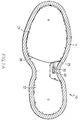
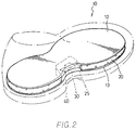
- the insole pad having a radio transmitter and receiver generally comprises an insole pad body 10, a fluid bag 20, a connecting portion 30, a pressure-sensitive sensor 45 (not shown in Figure 1), a thermostat 50 (not shown in Figure 1), a transmitting circuit 40, and a receiving circuit 70 (not shown in Figure 1).
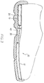
- the insole pad body 10 includes an upper protecting lining 12 and a lower protecting lining 13, and the fluid bag 20 is disposed there between.
- the fluid bag 20 is filled with fluid.
- the connecting portion 30, the sensor 45, the thermostat 50 and the transmitting circuit 40 are all installed onto the insole pad body 10.
- the insole pad body 10 can also be a single upper protecting lining 12 or lower protecting lining 13.
- the insole pad body 10 is a hollow lining 11 in which the fluid bag 20, the connecting portion 30, the sensor 45, the thermostat 50 and the transmitting circuit 40 can be disposed.
- the fluid bag 20 can be divided into a front chamber 21 and a rear chamber 22 by means of a partition 26.
- the front chamber 21 of the fluid bag 20 is provided with an outlet 25.
- Each of the front and rear chambers 21, 22 is provided with a reinforced rib 23 and a nozzle 24, wherein the reinforced rib 23 serves as enhancing the rigidity of the insole pad body 10.
- the nozzle 24 serves as an inlet for fluid.
- the outer portion of the connecting portion 30, the sensor 45, and the thermostat 50 are made by the same material.
- the connecting portion 30, the sensor 45 and the thermostat 50 can be joined together by means of heat-sealing or by adhesive.
- the sensor 45 and the thermostat 50 can be disposed within the fluid bag 20 such that it can be directly contacted with the fluid.
- the overall weight of the user will exert onto the fluid bag 20.
- the sensor 45 can detect the variation of the pressure within the fluid bag 20 in response to the weight of the user.
- the thermostat 50 can also detect the variation of the temperature within the fluid bag 20. The detected variations of the pressure and temperature can be converted into a signal, respectively.
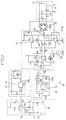
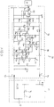
- the transmitting circuit 40 includes a first power circuit 41, a first amplifying circuit 46, a converting circuit 51, a first micro-controlling circuit 53, and a radio transmitting circuit 55.
- the first circuit 41 includes a pair of first cells 42, a first switch 43, and a breaker 44.
- the first cell 42 includes a pair of 1.5 V dc batteries, which are connected in series. Mercury or lithium batteries can also be used to provide the power required by the transmitting circuit 40.
- the first switch 43 is used to control the on/off of the power circuit 41. The power can be suitably switched off when not in use.
- the breaker 44 is a Ge-diode D1. The circuit can be suitably protected when the polarity of the first cell 42 is reversed.
- the first amplifying circuit 46 includes three amplifiers 47, a power adjusting element 48, and a reset element 49.
- the sensor 45 and the thermostat 50 are electrically connected to the first amplifying circuit 46.
- the amplifier 47 is commercially available and the model number is TLO74N, which is an OP operational amplifier.
- TLO74N which is an OP operational amplifier.
- the pressure and temperature signals sent from the sensor 45 and the thermostat 50 can be amplified and then are sent to the converting circuit 51.
- the signals can be amplified up to 250 times.
- the amplifying voltage power is controlled and adjusted by the power-adjusting element 48. Besides, when the insole pad body 10 is lifted from the ground, the pressure signal can be reset to zero by the reset element 49.
- the converting circuit 51 includes at least a converter 52.
- the pressure and temperature signal transmitted from the first amplifying circuit 46 will be sent to the converting circuit 51.
- These pressure and temperature signals will then be converted into a frequency signal, respectively, by the converter 52, and which are then sent to a micro-control circuit 53.
- the converter 52 is commercially available and the model number is XR-4151, V-F converter.
- the first micro-control circuit 53 includes a first micro-controller 54.
- the first micro-control circuit 53 can calculate the frequency signal so as to get a final value.
- the value includes the detected pressure, the number of stepping, and consumption of calories. These values will finally be sent to the radio transmitting circuit 55.
- the first micro-controller 54 is a commercially available and the model number is PIC12C508.
- the sensor 45 first detects the variation of the pressure, and this detected variation will be converted into a signal which can be transformed into a value by the first micro-controller 54. Accordingly, the weight of the user can be calculated. However, when the power of the transmitting circuit 40 is shut off, this pressure will be reset.
- the micro-controller 54 is preset with a threshold and when the pressure value detected by the sensor 45 is smaller than this threshold, it can be assured that the insole pad body 10 has been lifted from the ground. On the other hand, when the pressure value detected by the sensor 45 is larger than this threshold, it can be assured that the insole pad body 10 is pressed against the ground.
- the first micro-controller 54 will add 1 for each cycle. Accordingly, the mileage that the user has walked can be readily calculated.
- the approximate consumption of calories is first calculated from a multiplication of the pressure value and the number of stepping. Then this multiplication times a constant and the approximate consumed calories can be attained.
- the radio transmitting circuit 55 includes a modulator 56, a first resonating circuit 57, a transmitting antenna 58, and a frequency-modulating device 59.
- the modulator 56 can convert the received value into an Amplitude Modulation frequency. Then this AM frequency is further transformed into a lower energy, super-high radio frequency by the first resonating circuit 57 of high frequency LC, and finally, this high radio frequency can be transmitted by the antenna 58.
- the modulating device 59 for adjusting the radio frequency is attained by a variable capacitor C41.
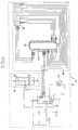
- the receiving circuit 70 includes a second power circuit 71, a signal receiving circuit 76, a second amplifying circuit 79, a frequency-detecting circuit 80, and a receiving-controlling circuit 81.
- the second power circuit 71 includes a pair of second batteries 72, a second switch 73, a breaker 74, and a plurality of filters 75.
- a pair of dc cells which are connected in series, configures the second batteries 72.
- the battery can also be replaced by a mercury or lithium battery.
- the second switch 73 is used to control the on/off of the second power circuit 71 and the power can be shut off when not in use.
- the breaker 74 is a Ge-diode D1, accordingly the circuit can be suitably protected when the polarity of the first battery 42 is reversed.
- the signal receiving circuit 76 can collect the radio frequency transmitted from the transmitting circuit 40.
- the signal receiving circuit 76 includes a filtering device 75, a receiving antenna 77, and a second resonating circuit 78.
- the radio frequency can be collected by the receiving antenna 77 and then be transmitted to the second resonating circuit 78.
- the second resonating circuit 78 is a tuner configured by the LC resonating.
- the radio frequency transmitted by the transmitting circuit 40 can be filtered and then be transmitted to the second amplifying circuit 79.
- a pair of induces L3, L4 are configured with the filtering device 75.
- Three transistors Q2, Q3 and Q4, that are connected in series, are configured with the second amplifying circuit 79.
- the radio frequency, which is collected and filtered can be further amplified.
- the amplified radio frequency is further transmitted to the frequency-detecting circuit 80 for detecting the frequency.
- the potential variation between whether there is a detected radio frequency can be verified.
- the potential variation is further transmitted to the receiving controlling circuit 81.
- the receiving controlling circuit 81 includes a second micro-controller 82, a function selecting circuit 84, and a liquid crystal displaying circuit 86.
- the second micro-controller 82 can decode the signal transmitted from the frequency-detecting circuit 80. Finally, the value transmitted from the transmitting circuit 40 can be attained.
- the user may select the information through the function-controlling circuit 84.
- the liquid crystal displaying circuit 86 includes a liquid crystal display driver 87 and a liquid crystal display 88.
- the liquid crystal display driver may receive the given signal which can be used to drive the liquid crystal display 88. As a result, the user can be advised by the selected information.
- the second micro-controller 82 is commercially available and is an IC bearing the model number PIC16C54.
- the receiving circuit 70 can be built into a watch 90.
- the receiving controlling circuit 81 is further provided with a beeper 83.
- the beeper 83 is a capacitor-type piezoelectric beeper and is electrically connected to the second micro-controller 82.
- the second micro-controller 82 is preset with a threshold, i.e. a certain amount of the stepping, the mileage, and the consumed calories. Accordingly, when the value from the transmitting circuit 40 is collected by the second micro-controller 82 and exceeds the preset threshold, the beeper 83 will be triggered so as to alarm the user.
- the connecting portion 30, the pressure sensor 45, the thermostat 50, and the transmitting circuit 40 are all disposed within the left insole pad body 10. And the value measured by the insole pad body 10 will be transmitted to the receiving circuit 70 or the watch 90. As a result, the user can be conveniently advised by the value displayed on the watch 90.
- the removable insole pad body 10 that bearing a radio transmitter, can be disposed within the shoe while the watch 90 be worn onto the wrist of the user. Then the mileage, the numbers of stepping, and the approximate consumed of calories can be readily measured and displayed.
Landscapes
- Engineering & Computer Science (AREA)
- Microelectronics & Electronic Packaging (AREA)
- Physics & Mathematics (AREA)
- General Physics & Mathematics (AREA)
- Radar, Positioning & Navigation (AREA)
- Remote Sensing (AREA)
- Footwear And Its Accessory, Manufacturing Method And Apparatuses (AREA)
- Arrangements For Transmission Of Measured Signals (AREA)
Priority Applications (4)
| Application Number | Priority Date | Filing Date | Title |
|---|---|---|---|
| US08/964,149 US5875571A (en) | 1997-11-06 | 1997-11-06 | Insole pad having step-counting device |
| ES97309030T ES2221020T3 (es) | 1997-11-06 | 1997-11-11 | Plantilla con dispositivo contador de pasos. |
| DE69728987T DE69728987T2 (de) | 1997-11-06 | 1997-11-11 | Einlegesohle mit Schritt-Zählvorrichtung |
| EP97309030A EP0916931B1 (de) | 1997-11-06 | 1997-11-11 | Einlegesohle mit Schritt-Zählvorrichtung |
Applications Claiming Priority (2)
| Application Number | Priority Date | Filing Date | Title |
|---|---|---|---|
| US08/964,149 US5875571A (en) | 1997-11-06 | 1997-11-06 | Insole pad having step-counting device |
| EP97309030A EP0916931B1 (de) | 1997-11-06 | 1997-11-11 | Einlegesohle mit Schritt-Zählvorrichtung |
Publications (2)
| Publication Number | Publication Date |
|---|---|
| EP0916931A1 true EP0916931A1 (de) | 1999-05-19 |
| EP0916931B1 EP0916931B1 (de) | 2004-05-06 |
Family
ID=26147692
Family Applications (1)
| Application Number | Title | Priority Date | Filing Date |
|---|---|---|---|
| EP97309030A Expired - Lifetime EP0916931B1 (de) | 1997-11-06 | 1997-11-11 | Einlegesohle mit Schritt-Zählvorrichtung |
Country Status (4)
| Country | Link |
|---|---|
| US (1) | US5875571A (de) |
| EP (1) | EP0916931B1 (de) |
| DE (1) | DE69728987T2 (de) |
| ES (1) | ES2221020T3 (de) |
Cited By (3)
| Publication number | Priority date | Publication date | Assignee | Title |
|---|---|---|---|---|
| WO2006003635A1 (en) * | 2004-07-02 | 2006-01-12 | Koninklijke Philips Electronics N.V. | Dynamically adjustable impact-buffering sports shoe |
| WO2006067434A1 (en) * | 2004-12-21 | 2006-06-29 | Powered Triangle Limited | Footwear and accessories therefor |
| ES2259491A1 (es) * | 2003-08-04 | 2006-10-01 | Asociacion De Investigacion Para La Industria Del Calzado Y Conexas (Inescop) | Dispositivo programable de monitorizacion continua del pie en condiciones normales de marcha, adaptable a cualquier calzado convencional. |
Families Citing this family (46)
| Publication number | Priority date | Publication date | Assignee | Title |
|---|---|---|---|---|
| US6578291B2 (en) * | 2000-06-06 | 2003-06-17 | John Hirsch | Shoe wear indicator |
| AU2002255568B8 (en) | 2001-02-20 | 2014-01-09 | Adidas Ag | Modular personal network systems and methods |
| US20050195094A1 (en) * | 2004-03-05 | 2005-09-08 | White Russell W. | System and method for utilizing a bicycle computer to monitor athletic performance |
| DE102004045176B4 (de) * | 2004-09-17 | 2011-07-21 | Adidas International Marketing B.V. | Blase |
| US7114822B2 (en) * | 2004-11-12 | 2006-10-03 | Bbc International, Ltd. | Article of footwear with remote sound activating unit |
| US7254516B2 (en) * | 2004-12-17 | 2007-08-07 | Nike, Inc. | Multi-sensor monitoring of athletic performance |
| DE102005014709C5 (de) | 2005-03-31 | 2011-03-24 | Adidas International Marketing B.V. | Schuh |
| US20070169381A1 (en) * | 2006-01-23 | 2007-07-26 | Gordon Steven N | Shoe Pedometer |
| US20100004566A1 (en) * | 2008-01-11 | 2010-01-07 | Esoles, L,L.C. | Intelligent orthotic insoles |
| US7921716B2 (en) * | 2008-03-20 | 2011-04-12 | University Of Utah Research Foundation | Method and system for measuring energy expenditure and foot incline in individuals |
| US9591993B2 (en) * | 2008-03-20 | 2017-03-14 | University Of Utah Research Foundation | Method and system for analyzing gait and providing real-time feedback on gait asymmetry |
| US8384551B2 (en) * | 2008-05-28 | 2013-02-26 | MedHab, LLC | Sensor device and method for monitoring physical stresses placed on a user |
| US7969315B1 (en) | 2008-05-28 | 2011-06-28 | MedHab, LLC | Sensor device and method for monitoring physical stresses placed upon a user |
| US9655405B2 (en) * | 2010-04-22 | 2017-05-23 | Kristan Lisa Hamill | Insoles for tracking, data transfer systems and methods involving the insoles, and methods of manufacture |
| US9940682B2 (en) | 2010-08-11 | 2018-04-10 | Nike, Inc. | Athletic activity user experience and environment |
| WO2012036428A2 (ko) * | 2010-09-16 | 2012-03-22 | Kim Jung Bae | 플렉서블 디스플레이를 포함하는 신체활동지수 계측기 및 이를 포함하는 신발깔창 |
| US8850716B2 (en) * | 2010-12-28 | 2014-10-07 | Schawbel Technologies Llc | Heated insole remote control systems |
| US9453772B2 (en) * | 2011-03-24 | 2016-09-27 | MedHab, LLC | Method of manufacturing a sensor insole |
| US9993181B2 (en) | 2011-03-24 | 2018-06-12 | Med Hab, LLC | System and method for monitoring a runner'S gait |
| US10004946B2 (en) | 2011-03-24 | 2018-06-26 | MedHab, LLC | System and method for monitoring power applied to a bicycle |
| CN102853844A (zh) * | 2011-06-27 | 2013-01-02 | 富泰华工业(深圳)有限公司 | 计步系统及具有数据传输功能的计步器 |
| WO2013101920A1 (en) | 2011-12-30 | 2013-07-04 | The Schawbel Corporation | Heated insoles |
| US9510646B2 (en) | 2012-07-17 | 2016-12-06 | Nike, Inc. | Article of footwear having a flexible fluid-filled chamber |
| DE102013202485B4 (de) | 2013-02-15 | 2022-12-29 | Adidas Ag | Ball für eine Ballsportart |
| US9314064B2 (en) | 2013-12-04 | 2016-04-19 | Schawbel Technologies Llc | Heated insole with removable heating assembly |
| CA2930858C (en) | 2013-12-04 | 2021-01-26 | Schawbel Technologies Llc | Heated insole with removable and rechargeable battery |
| US9572397B2 (en) | 2013-12-04 | 2017-02-21 | Schawbel Technologies Llc | Heated insole with removable assembly |
| US9320320B1 (en) | 2014-01-10 | 2016-04-26 | Harry A. Shamir | Exercise shoe |
| USD737769S1 (en) | 2014-04-09 | 2015-09-01 | Schawbel Technologies Llc | Battery pack for an insole |
| USD734012S1 (en) | 2014-04-09 | 2015-07-14 | Schawbel Technologies Llc | Insole |
| US10638927B1 (en) * | 2014-05-15 | 2020-05-05 | Casca Designs Inc. | Intelligent, additively-manufactured outerwear and methods of manufacturing thereof |
| US10016941B1 (en) | 2014-05-15 | 2018-07-10 | Feetz, Inc. | Systems and methods for measuring body parts for designing customized outerwear |
| US10241498B1 (en) | 2014-05-15 | 2019-03-26 | Feetz, Inc. | Customized, additive-manufactured outerwear and methods for manufacturing thereof |
| CN104207409B (zh) * | 2014-09-22 | 2017-06-30 | 吉林大学 | 一种压力自感知、自发电的智能鞋垫 |
| WO2016154507A1 (en) * | 2015-03-25 | 2016-09-29 | Son Jae S | Apparatuses, devices, and methods for measuring fluid pressure variation in an insole |
| WO2016161259A1 (en) | 2015-04-03 | 2016-10-06 | Schawbel Technologies Llc | Portable heating systems |
| US10222283B2 (en) * | 2015-04-08 | 2019-03-05 | Smart Skin Technologies Inc. | Systems and methods of providing automated feedback to a user using a shoe insole assembly |
| CN107690291B (zh) | 2015-05-28 | 2021-06-29 | 耐克创新有限合伙公司 | 具有内部共形电子器件的鞋类垫 |
| WO2016205465A1 (en) | 2015-06-16 | 2016-12-22 | Sridhar Iyengar | Apparatuses, devices, and methods for measuring insole deformation |
| USD794813S1 (en) | 2015-07-15 | 2017-08-15 | Schawbel Technologies Llc | Heat pack |
| WO2018086678A1 (en) * | 2016-11-09 | 2018-05-17 | Power2Watt B.V. | Power measuring sporting shoe |
| US11638554B2 (en) | 2018-02-21 | 2023-05-02 | T.J.Smith And Nephew, Limited | Negative pressure dressing system with foot load monitoring |
| NL2020897B1 (en) * | 2018-05-08 | 2019-11-14 | Power2Watt B V | Apparatus and methods for recording power output during an activity. |
| EP3804452A1 (de) | 2018-06-04 | 2021-04-14 | T.J. Smith & Nephew, Limited | Gerätekommunikationsverwaltung bei benutzeraktivitätsüberwachungssystemen |
| US11350877B2 (en) * | 2018-09-24 | 2022-06-07 | Arizona Board Of Regents On Behalf Of Arizona State University | Smart shoes with adaptive sampling for rehabilitation and health monitoring |
| JP7544740B2 (ja) | 2019-05-01 | 2024-09-03 | ティージェイ スミス アンド ネフュー リミテッド | ユーザ活動監視システムにおける通信およびユーザインターフェース制御 |
Citations (6)
| Publication number | Priority date | Publication date | Assignee | Title |
|---|---|---|---|---|
| US4763287A (en) * | 1986-05-24 | 1988-08-09 | Puma Ag Rudolf Dassler Sport | Measuring performance information in running disciplines and shoe systems |
| US5323650A (en) * | 1993-01-14 | 1994-06-28 | Fullen Systems, Inc. | System for continuously measuring forces applied to the foot |
| WO1995014430A1 (en) * | 1993-11-22 | 1995-06-01 | Della Ca Pietro | Method for determination of the weight of human body and device for performing the method |
| US5471405A (en) * | 1992-11-13 | 1995-11-28 | Marsh; Stephen A. | Apparatus for measurement of forces and pressures applied to a garment |
| US5655316A (en) * | 1995-12-11 | 1997-08-12 | Raymond Hwang | Shoe with weighing and step counting means |
| US5661916A (en) * | 1996-07-05 | 1997-09-02 | Huang; Tien-Tsai | Electronic step counting shoe |
Family Cites Families (5)
| Publication number | Priority date | Publication date | Assignee | Title |
|---|---|---|---|---|
| US3702999A (en) * | 1971-02-22 | 1972-11-14 | Ivan A Gradisar | Partial weight bear warning device |
| US3974491A (en) * | 1974-07-22 | 1976-08-10 | Smithkline Corporation | Load signaling device for a patient's foot |
| US5230249A (en) * | 1990-08-20 | 1993-07-27 | Casio Computer Co., Ltd. | Shoe or boot provided with tank chambers |
| US5195254A (en) * | 1991-06-24 | 1993-03-23 | Tyng Liou Y | Sole |
| US5673500A (en) * | 1995-12-11 | 1997-10-07 | Raymond Hwang | Shoe with weighing means |
-
1997
- 1997-11-06 US US08/964,149 patent/US5875571A/en not_active Expired - Fee Related
- 1997-11-11 ES ES97309030T patent/ES2221020T3/es not_active Expired - Lifetime
- 1997-11-11 EP EP97309030A patent/EP0916931B1/de not_active Expired - Lifetime
- 1997-11-11 DE DE69728987T patent/DE69728987T2/de not_active Expired - Fee Related
Patent Citations (6)
| Publication number | Priority date | Publication date | Assignee | Title |
|---|---|---|---|---|
| US4763287A (en) * | 1986-05-24 | 1988-08-09 | Puma Ag Rudolf Dassler Sport | Measuring performance information in running disciplines and shoe systems |
| US5471405A (en) * | 1992-11-13 | 1995-11-28 | Marsh; Stephen A. | Apparatus for measurement of forces and pressures applied to a garment |
| US5323650A (en) * | 1993-01-14 | 1994-06-28 | Fullen Systems, Inc. | System for continuously measuring forces applied to the foot |
| WO1995014430A1 (en) * | 1993-11-22 | 1995-06-01 | Della Ca Pietro | Method for determination of the weight of human body and device for performing the method |
| US5655316A (en) * | 1995-12-11 | 1997-08-12 | Raymond Hwang | Shoe with weighing and step counting means |
| US5661916A (en) * | 1996-07-05 | 1997-09-02 | Huang; Tien-Tsai | Electronic step counting shoe |
Non-Patent Citations (2)
| Title |
|---|
| R.B. FROST ET AL.: "A load cell and sole assembly for dynamic pointwise vertical force measurement in walking", ENGINEERING IN MEDICINE., vol. 10, no. 1, January 1981 (1981-01-01), LONDON GB, pages 45 - 50, XP002059133 * |
| S. MIYAZAKI: "Foot-force measuring device for clinical assessment of pathological gait", MEDICAL AND BIOLOGICAL ENGINEERING AND COMPUTING., vol. 16, no. 4, July 1978 (1978-07-01), STEVENAGE GB, pages 429 - 436, XP002059132 * |
Cited By (4)
| Publication number | Priority date | Publication date | Assignee | Title |
|---|---|---|---|---|
| ES2259491A1 (es) * | 2003-08-04 | 2006-10-01 | Asociacion De Investigacion Para La Industria Del Calzado Y Conexas (Inescop) | Dispositivo programable de monitorizacion continua del pie en condiciones normales de marcha, adaptable a cualquier calzado convencional. |
| ES2259491B1 (es) * | 2003-08-04 | 2007-12-01 | Asociacion De Investigacion Para La Industria Del Calzado Y Conexas (Inescop) | Dispositivo programable de monitorizacion continua del pie en condiciones normales de marcha, adaptable a cualquier calzado convencional. |
| WO2006003635A1 (en) * | 2004-07-02 | 2006-01-12 | Koninklijke Philips Electronics N.V. | Dynamically adjustable impact-buffering sports shoe |
| WO2006067434A1 (en) * | 2004-12-21 | 2006-06-29 | Powered Triangle Limited | Footwear and accessories therefor |
Also Published As
| Publication number | Publication date |
|---|---|
| US5875571A (en) | 1999-03-02 |
| DE69728987T2 (de) | 2004-10-21 |
| DE69728987D1 (de) | 2004-06-09 |
| ES2221020T3 (es) | 2004-12-16 |
| EP0916931B1 (de) | 2004-05-06 |
Similar Documents
| Publication | Publication Date | Title |
|---|---|---|
| US5875571A (en) | Insole pad having step-counting device | |
| US5815954A (en) | Shoe with an electronic step counter | |
| US5721539A (en) | Speedometer for in-line skates | |
| US6011491A (en) | Speedometer for in-line skates | |
| US4578769A (en) | Device for determining the speed, distance traversed, elapsed time and calories expended by a person while running | |
| US7493232B1 (en) | Device and method for monitoring hydration status | |
| JP5926511B2 (ja) | 美容・健康モニタリングシステム | |
| US7229416B2 (en) | Exercise expenditure monitor device and method | |
| US20060248965A1 (en) | Systems and methods of power output measurement | |
| US20050245793A1 (en) | Personal wellness monitor system and process | |
| CN201790034U (zh) | 设有采集并传输运动数据智能模块的鞋子 | |
| US6805006B2 (en) | Method and apparatus for measuring the maximum speed of a runner over a prescribed distance including a transmitter and receiver | |
| US5797201A (en) | Shoe with step counting capability | |
| JP2002519754A (ja) | 柔軟なディスプレイを有する着用装置 | |
| EP3352652A1 (de) | Hydrierungsüberwachungssystem | |
| KR20090102264A (ko) | 웨어러블 측정 장치 | |
| EP0917893B1 (de) | Geschwindigkeitsmesser für In-Line-Skating | |
| CN106388792A (zh) | 智能手环 | |
| JP2018192240A (ja) | ウェアラブルデバイス | |
| US5661916A (en) | Electronic step counting shoe | |
| JPH0614803A (ja) | 運動情報を収集する運動靴 | |
| EP1967823A1 (de) | Überwachungssystem | |
| CN1089221C (zh) | 无线电发射活动式流体鞋垫及其接收器 | |
| La Rosa et al. | An energy autonomous and battery-free measurement system for ambient light power with time domain readout | |
| US20120099617A1 (en) | Electronic clinical thermometer |
Legal Events
| Date | Code | Title | Description |
|---|---|---|---|
| PUAI | Public reference made under article 153(3) epc to a published international application that has entered the european phase |
Free format text: ORIGINAL CODE: 0009012 |
|
| AK | Designated contracting states |
Kind code of ref document: A1 Designated state(s): DE ES FR GB IT NL |
|
| AX | Request for extension of the european patent |
Free format text: AL;LT;LV;MK;RO;SI |
|
| 17P | Request for examination filed |
Effective date: 19991115 |
|
| AKX | Designation fees paid |
Free format text: DE ES FR GB IT NL |
|
| GRAP | Despatch of communication of intention to grant a patent |
Free format text: ORIGINAL CODE: EPIDOSNIGR1 |
|
| GRAA | (expected) grant |
Free format text: ORIGINAL CODE: 0009210 |
|
| GRAS | Grant fee paid |
Free format text: ORIGINAL CODE: EPIDOSNIGR3 |
|
| AK | Designated contracting states |
Kind code of ref document: B1 Designated state(s): DE ES FR GB IT NL |
|
| REG | Reference to a national code |
Ref country code: GB Ref legal event code: FG4D |
|
| REF | Corresponds to: |
Ref document number: 69728987 Country of ref document: DE Date of ref document: 20040609 Kind code of ref document: P |
|
| PGFP | Annual fee paid to national office [announced via postgrant information from national office to epo] |
Ref country code: ES Payment date: 20041006 Year of fee payment: 8 |
|
| PGFP | Annual fee paid to national office [announced via postgrant information from national office to epo] |
Ref country code: NL Payment date: 20041123 Year of fee payment: 8 |
|
| REG | Reference to a national code |
Ref country code: ES Ref legal event code: FG2A Ref document number: 2221020 Country of ref document: ES Kind code of ref document: T3 |
|
| ET | Fr: translation filed | ||
| PLBE | No opposition filed within time limit |
Free format text: ORIGINAL CODE: 0009261 |
|
| STAA | Information on the status of an ep patent application or granted ep patent |
Free format text: STATUS: NO OPPOSITION FILED WITHIN TIME LIMIT |
|
| 26N | No opposition filed |
Effective date: 20050208 |
|
| PG25 | Lapsed in a contracting state [announced via postgrant information from national office to epo] |
Ref country code: IT Free format text: LAPSE BECAUSE OF NON-PAYMENT OF DUE FEES Effective date: 20051111 |
|
| PG25 | Lapsed in a contracting state [announced via postgrant information from national office to epo] |
Ref country code: ES Free format text: LAPSE BECAUSE OF NON-PAYMENT OF DUE FEES Effective date: 20051112 |
|
| PGFP | Annual fee paid to national office [announced via postgrant information from national office to epo] |
Ref country code: GB Payment date: 20051115 Year of fee payment: 9 |
|
| PGFP | Annual fee paid to national office [announced via postgrant information from national office to epo] |
Ref country code: FR Payment date: 20051128 Year of fee payment: 9 |
|
| PGFP | Annual fee paid to national office [announced via postgrant information from national office to epo] |
Ref country code: DE Payment date: 20051129 Year of fee payment: 9 |
|
| PG25 | Lapsed in a contracting state [announced via postgrant information from national office to epo] |
Ref country code: NL Free format text: LAPSE BECAUSE OF NON-PAYMENT OF DUE FEES Effective date: 20060601 |
|
| NLV4 | Nl: lapsed or anulled due to non-payment of the annual fee |
Effective date: 20060601 |
|
| REG | Reference to a national code |
Ref country code: ES Ref legal event code: FD2A Effective date: 20051112 |
|
| PG25 | Lapsed in a contracting state [announced via postgrant information from national office to epo] |
Ref country code: DE Free format text: LAPSE BECAUSE OF NON-PAYMENT OF DUE FEES Effective date: 20070601 |
|
| GBPC | Gb: european patent ceased through non-payment of renewal fee |
Effective date: 20061111 |
|
| REG | Reference to a national code |
Ref country code: FR Ref legal event code: ST Effective date: 20070731 |
|
| PG25 | Lapsed in a contracting state [announced via postgrant information from national office to epo] |
Ref country code: GB Free format text: LAPSE BECAUSE OF NON-PAYMENT OF DUE FEES Effective date: 20061111 |
|
| PG25 | Lapsed in a contracting state [announced via postgrant information from national office to epo] |
Ref country code: FR Free format text: LAPSE BECAUSE OF NON-PAYMENT OF DUE FEES Effective date: 20061130 |