EP0916935B1 - Dispositif et méthode pour tester la résistance des roues de véhicules - Google Patents
Dispositif et méthode pour tester la résistance des roues de véhicules Download PDFInfo
- Publication number
- EP0916935B1 EP0916935B1 EP98120054A EP98120054A EP0916935B1 EP 0916935 B1 EP0916935 B1 EP 0916935B1 EP 98120054 A EP98120054 A EP 98120054A EP 98120054 A EP98120054 A EP 98120054A EP 0916935 B1 EP0916935 B1 EP 0916935B1
- Authority
- EP
- European Patent Office
- Prior art keywords
- load
- wheel
- force
- forces
- parallel
- Prior art date
- Legal status (The legal status is an assumption and is not a legal conclusion. Google has not performed a legal analysis and makes no representation as to the accuracy of the status listed.)
- Expired - Lifetime
Links
- 238000012360 testing method Methods 0.000 title claims description 41
- 238000000034 method Methods 0.000 title claims description 15
- 238000005452 bending Methods 0.000 description 19
- 238000010998 test method Methods 0.000 description 6
- 238000010276 construction Methods 0.000 description 4
- 210000000078 claw Anatomy 0.000 description 2
- 230000001419 dependent effect Effects 0.000 description 2
- 238000002474 experimental method Methods 0.000 description 2
- 238000007792 addition Methods 0.000 description 1
- 230000006835 compression Effects 0.000 description 1
- 238000007906 compression Methods 0.000 description 1
- 238000013461 design Methods 0.000 description 1
- 238000009661 fatigue test Methods 0.000 description 1
- 239000012530 fluid Substances 0.000 description 1
- 238000005259 measurement Methods 0.000 description 1
- 230000036316 preload Effects 0.000 description 1
- 238000005096 rolling process Methods 0.000 description 1
- 230000003068 static effect Effects 0.000 description 1
- 238000012546 transfer Methods 0.000 description 1
Images


Classifications
-
- G—PHYSICS
- G01—MEASURING; TESTING
- G01M—TESTING STATIC OR DYNAMIC BALANCE OF MACHINES OR STRUCTURES; TESTING OF STRUCTURES OR APPARATUS, NOT OTHERWISE PROVIDED FOR
- G01M17/00—Testing of vehicles
- G01M17/007—Wheeled or endless-tracked vehicles
- G01M17/013—Wheels
Definitions
- the invention relates to a device for strength testing of motor vehicle wheels according to the preamble of claim 1.
- the invention is also based on a method for testing the strength of essentially one wheel rim and one connected wheel bowl existing motor vehicle wheels directed according to the preamble of claim 13.
- Motor vehicle wheels are subject to high loads in their operation, mainly due to the wheel contact forces in Result of the weight of the vehicle and the wheel side forces arise when cornering or driving on a slope.
- Devices known, also known as rotary bending testing machines be designated.
- the wheel rim is fixed to a machine Clamping device clamped and the wheel bowl connected to a load introduction element in the form of a lever arm, the one at its free end by a rotating eccentric applied with a moment and a rotating radial load becomes.
- the wheel is used for weight-loaded machines usually with its rim on a rotatable jig attached while a load transfer element on the wheel disc attacks in the form of a lever arm, on the free end a transverse force acts and so on the wheel bowl exerts a bending moment and a radial force.
- Circulation bending testing machines known (DE 41 11 265 A1), in which do not use claws on the rim flange to hold the wheel is clamped, but in which the wheel relative to the jig Can perform pivoting movements around the to avoid otherwise existing disadvantage, symmetrical loads to evoke those that occur in actual operation, incorrectly simulate asymmetrical loads.
- This known testing machine is therefore not available to an axial clamping of the wheel only one lengthways Axial, tensile articulation of the test specimen Provided at the end of the journal.
- the known machines have the disadvantage that when machine the machine to different lever arm lengths can be loaded with equally large bending moments radial forces acting simultaneously on the wheel however are different. This has different localities Stresses on the same wheel when checking it in various rotary bending testing machines, so that divergent fracture positions and service life values result and the test results obtained from two test machines are hardly comparable with each other. Often are defined Lever arm lengths specified; but it has continued to this day cannot enforce a uniform measure for the lever arm length and there are still bending testing machines with different ones Arm lengths in use.
- rotary bending testing machines are known in which the radial force is introduced by a complicated lever arm gear in the load plane of the wheel contact force or in which the stress on the wheel in the two directions parallel and radially to the wheel axis by dividing the force results into an axial - And a radial force is realized at a suitable position.
- the object of the invention is an apparatus and a method of the generic type so that it is possible is the entire test range of one with just one machine Load of the wheel only with a pure radial force or with a pure axial force without moment up to one Load with a pure moment without radial force or without Simulate axial force, regardless of the dimensions of the wheel to be tested.
- the method according to the invention and the device should therefore be able to Load types of the known bending testing machines for practically everyone Imitate wheel sizes.
- the load force thus generated preferably has a line of action that is at right angles to the Lines of action of the two parallel load forces can by the three exerted on the load introduction element
- Load forces are the wheel contact force acting on the wheel while driving and wheel lateral force at any wheel contact point can be simulated on the test bench without changing the geometry, see above that with one and the same device reliable test results won for bikes of different dimensions can be a reliable statement of their strength allow.
- That of the load force generators on the load introduction element Forces to be exercised can simply be Taking into account the force application points of the load force generators by drawing up the equations of moment and force equilibrium around the wheel mounting point, where the wheel contact and lateral forces to be simulated and the Dimensions for the tire radius and the offset are specified under which they attack while driving in the wheel.
- the load power generators are expediently hydraulic cylinders, preferably around cylinders acting on both sides, with which it is possible to change forces of any size of the hydraulic pressure in the hydraulic system in a large Generate area.
- the load introduction element expediently consists essentially from a lever arm that can be connected coaxially and rotatably to the wheel.
- the wheel itself is preferably on with its wheel rim the jig can be attached while the load application element is connected to the wheel bowl.
- the jig advantageously consists essentially of a clamping plate arranged on a drive shaft the wheel with one or both rim flanges using clamping jaws can be set.
- the load introduction element is preferably at its wheel end with a bearing element similar to a steering knuckle with a wheel bearing for Provide connection to the wheel that the relative rotatability of clamping device and load introduction element.
- a particularly advantageous embodiment results if the load force generators for the parallel load forces are orthogonal to the wheel axle on the load introduction element.
- a load force generator used hydraulic cylinders working parallel to each other a free moment and also a radial force to exercise on the bike, what a burden of just by a wheel contact force corresponding to that at a distance or an offset from the clamping surface of the wheel on the Attacks the wheel hub.
- this Load force generator for the anti-parallel load forces in parallel to allow the wheel to engage the load introduction element.
- load force generators preferably acts orthogonally to the lines of action of the two parallel load forces on the load introduction element on. This configuration allows a simple one and quick calculation of the three load forces.
- the wheel rim is useful with its outer rim flange the jig can be attached. This enables a special quick assembly of the wheel on the test bench. If this is in individual cases, it is of course also possible to design the jig so that the wheel rim can be attached to it with its inner rim flange or even so that the jig both attaches to the wheel rim holds their inner as well as on their outer rim flange. In these cases, the jig can be made using a hollow shaft be rotatably mounted on the machine frame, the load introduction element then the hollow shaft interspersed with play.
- the invention is based on the knowledge that it can be produced of a free moment due to two anti-parallel load forces the bending moment curve of another, load level acting on the load introduction element in its level to postpone what a change in position of the resultant force is completely equivalent.
- Fig. 1 shows a schematic representation of a wheel hub 10 mounted motor vehicle wheel 11, which consists essentially of a Wheel bowl 12 and a wheel rim 13 connected thereto, on which the tire 14 for the wheel is mounted.
- Wheel contact force Fv and wheel side force Fh load the wheel or its wheel disc 12 with a bending moment M, a radial force R and an axial force A.
- This load which, with the same size and direction of the resultant force Fg, depends on the distance b and the radius r of the tire varies, should be simulated realistically during a fatigue test on a test bench. The method described below is used for this purpose, which is carried out with the aid of the device according to the invention shown in FIGS. 2 to 5.
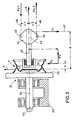
- Fig. 2 shows a schematic representation of a first embodiment a test device 21 according to the invention for motor vehicle wheels, with a jig 22 which is essentially from a drive shaft rotatably mounted on the machine frame 23 24 and a platen 25 connected thereto. On the platen 25, the vehicle wheel 11 is on his outer rim flange 26 clamped with holding claws, not shown.
- the device also has a load introduction element 27 in the form of a lever arm 28 on its wheel-side End 29 is provided with a bearing element 30 with which it on the wheel disc 12 by means of screws, not shown, coaxially and is rotatably connected.
- the lever arm 28 engages at fixed intervals a1, a2 from the contact surface 19 two load force generators 31 in the form of hydraulic cylinders 32 on, with their cylinder-side end on the machine frame 23 support.
- the hydraulic cylinders 32 are arranged that their piston rods 33 are orthogonal to the wheel axis 20 run so that they are on the lever arm 28 two parallel to each other current load forces Fr1, Fr2 can generate, their lines of action 34 and 35 also orthogonal to the wheel axis 20 are.
- a is at a third load application point 36 third load force generator 37 in the form of a hydraulic cylinder arranged, but which is aligned coaxially to the wheel axis 20 and a force Fa on the load introduction element via its piston rod 27 can exercise, the line of action 38 with the The wheel axis coincides and is therefore orthogonal to the two other, parallel forces Fr1, Fr2. All three hydraulic cylinders are independent of each other via pressure medium lines 39 can be pressurized with hydraulic fluid under pressure and can therefore use forces of any size positive as well as negative sign in their direction of movement exert on the load introduction element 27.
- the load forces Fa, Fr1, Fr2 can be clearly determined as a function of the specified values of the distance b , the tire radius r , the wheel contact force Fv and the wheel side force Fh.
- the forces calculated in this way can be set exactly by the hydraulic cylinders by adjusting the pressure conditions in their cylinder or annular spaces 40 or 41, for which purpose these are expediently provided with load cells (not shown) between the machine frame 23 and the load application points 36. If the clamping device 22 is driven to rotate with the wheel mounted thereon, as indicated by the arrow 42, the wheel bowl is subjected to a very realistic stress in the circulation bending test method as in driving operation.
- the device described it is also possible with the device described to also simulate the operation of simpler rotary bending testing machines, for example such a machine which exerts only a radial force acting on the wheel at a distance b from the contact surface 19 and a corresponding bending moment.
- the then predetermined lever arm length and the likewise predetermined radial force can be simulated by the load force generators 31 without changing the load application points 36, in which case the third load force generator 37 does not exert any axial force on the lever arm 28 in this special case.
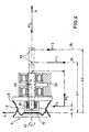
- Fig. 3 shows a second embodiment of the device according to the invention.
- the load introduction element 27 is provided at its rear, free end 43 with a cantilever plate 44 projecting radially on two sides from the lever arm 28.
- At the radially outer end of the cantilever plate 44 there are two load application points 45 at distances c1, c2 from the wheel axis 20, at which two load force generators act, which are not shown separately in the present case, but which, as in the embodiment shown in FIG. 2, are essentially consist of hydraulic cylinders.
- the axial forces Fa1, Fa2 exerted by these load force generators on the load introduction element 27 have lines of action 46 which run parallel to one another and to the wheel axis 20.
- a third load force generator acts, which is also not shown for the sake of simplicity and which can exert a third force Fr on the load application element, the line of action 47 of which is perpendicular the lines of action of the two axial forces Fa1, Fa2.
- the device is the wheel 11 on its inner rim flange 48 attached to the platen 25.
- the drive shaft 24 of the jig as Hollow shaft designed and the load introduction element 27 passes through the hollow shaft with play e and protrudes from the rear Late 50's out of this.
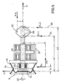
- Parallel load force generators (not shown) that are radial Load forces FR1, FR2 directed towards the wheel axis on the load introduction element 27 can exercise.
- a third (also not shown) load force generator can on the load introduction element 27 exert an axial load Fa.
- FIG. 5 largely corresponds to the device according to FIG. 4; However, here the axial force Fa does not act exactly centrally in the X-axis of the load introduction element 27, but under an axial offset c at a load application point 45.
- the described device and the method are suitable for Testing of practically all motor vehicle wheels including cast wheels, Truck wheels etc.
Landscapes
- Physics & Mathematics (AREA)
- General Physics & Mathematics (AREA)
- Investigating Strength Of Materials By Application Of Mechanical Stress (AREA)
Claims (18)
- Dispositif pour tester la résistance de roues de véhicule (11) essentiellement constituées d'une jante (13) et d'un flasque (12) qui y est raccordé, comprenant un élément de mise en charge (27) pouvant être raccordé à la jante (13) ou au flasque (12), et sur lequel deux générateurs de force de chargement (31) sont appliqués à distance (a2 - al) l'un de l'autre, les forces de chargement (Fr1, Fr2) pouvant ainsi être générées agissant parallèlement l'une à l'autre sur l'élément de mise en charge (27), tandis qu'un troisième générateur de force de chargement (37) est appliqué sur l'élément de mise en charge (27) de telle manière que la troisième force de chargement (Fa) ainsi générée a une ligne d'action (38) qui forme un angle avec les lignes d'action (34, 35) des deux forces de chargement parallèles (Fr1, Fr2), caractérisé en ce que les forces de chargement (Fr1, Fr2, Fa) sont librement réglables en valeur, et en ce qu'il est prévu pour l'autre respectif des composants de la roue (12 ou respectivement 13) un dispositif de bridage (22) qui est monté sur un cadre de machine (23) du dispositif (21), avec possibilité pour le dispositif de bridage de tourner et d'être entraíné par rapport à l'élément de mise en charge (27).
- Dispositif selon la revendication 1, caractérisé en ce que les générateurs de force de chargement (31, 37) sont des vérins hydrauliques (32).
- Dispositif selon la revendication 1 ou 2, caractérisé en ce que l'élément de mise en charge (27) est essentiellement constitué d'un bras de levier (28) pouvant être raccordé à la roue (11) de façon rotative et sensiblement coaxiale.
- Dispositif selon l'une des revendications 1 à 3, caractérisé en ce que la roue (11) peut être fixée au dispositif de bridage (22) par sa jante (13) et l'élément de mise en charge (27) peut être raccordé au flasque (12) de la roue.
- Dispositif selon l'une des revendications 1 à 4, caractérisé en ce que le dispositif de bridage (22) est essentiellement constitué d'une plaque de bridage (25) montée sur un arbre d'entraínement (24).
- Dispositif selon l'une des revendications 1 à 5, caractérisé en ce que l'élément de mise en charge (27) est muni d'un élément de palier (30) à son extrémité (29) côté roue, pour le raccordement à la roue (11).
- Dispositif selon l'une des revendications 1 à 6, caractérisé en ce que les générateurs de forces de chargement (31) pour les forces de chargement parallèles (Fr1, Fr2) sont appliqués sur l'élément de mise en charge (27) orthogonalement à l'axe de roue (20).
- Dispositif selon l'une des revendications 1 à 7, caractérisé en ce que les générateurs de forces de chargement pour les forces de chargement parallèles (Fa1, Fa2) sont appliqués sur l'élément de mise en charge (27) parallèlement à l'axe de roue (20).
- Dispositif selon l'une des revendications 1 à 8, caractérisé en ce que le générateur de force de chargement (37) pour la troisième force de chargement (Fa) est appliqué sur l'élément de mise en charge (27) orthogonalement aux lignes d'action (34, 35) des forces de chargement parallèles (Fr1, Fr2).
- Dispositif selon l'une des revendications 1 à 9, caractérisé en ce que la jante (13) de la roue peut être fixée au dispositif de bridage (22) par son bord de jante extérieur (26).
- Dispositif selon l'une des revendications 1 à 10, caractérisé en ce que la jante (13) de la roue peut être fixée au dispositif de bridage (22) par son bord de jante intérieur (48).
- Dispositif selon l'une des revendications 1 à 11, caractérisé en ce que le dispositif de bridage (22) est monté rotatif sur le cadre de machine (23) au moyen d'un arbre creux (49), l'élément de mise en charge (27) traversant l'arbre creux (49) avec jeu (e).
- Procédé pour tester la résistance de roues de véhicule essentiellement constituées d'une jante (13) de la roue et d'un flasque (12) de la roue, dans lequel par l'intermédiaire d'un élément de mise en charge (27), on exerce sur le flasque (12) de la roue un chargement simulant la force d'appui de la roue et la force latérale de la roue (Fv, Fh) en circulation, la charge étant produite sous la forme d'un moment libre s'exerçant sur l'élément de mise en charge (27), généré par deux forces anti-parallèles, d'une force additionnelle appliquée à l'élément de mise en charge (27) en un des points d'application de charge (36) du moment libre parallèlement aux lignes d'action des forces de chargement anti-parallèles, ainsi que d'une autre force (Fa), dont la ligne d'action (38) est perpendiculaire aux lignes d'action (34, 35) de la première force et des forces de chargement anti-parallèles, caractérisé en ce que l'on fixe la roue par sa jante (13) sur un dispositif de bridage (22) que l'on fait tourner par rapport à l'élément de mise en charge (27) pendant que s'exerce le chargement, et en ce que les valeurs du moment et des forces peuvent être choisies librement.
- Procédé selon la revendication 13, caractérisé en ce que les deux forces anti-parallèles générant le moment libre agissent sur l'élément de mise en charge (27) en des points d'application de force (36) fixes.
- Procédé selon la revendication 14, caractérisé en ce que les forces anti-parallèles agissent sur l'élément de mise en charge (27) orthogonalement à l'axe de rotation (20) de la roue (11).
- Procédé selon la revendication 14, caractérisé en ce que les forces anti-parallèles agissent sur l'élément de mise en charge (27) parallèlement à l'axe de rotation (20) de la roue (11).
- Procédé selon l'une des revendications 13 à 16, caractérisé en ce que le moment libre et les forces sont générées au moyen de vérins hydrauliques (32) appliqués sur l'élément de mise en charge (27) en des points d'application d'effort fixes (36).
- Procédé selon l'une des revendications 13 à 17, caractérisé en ce que les valeurs des forces (Fr1, Fr2, Fa ou respectivement Fa1, Fa2, Fr) appliquées aux points d'application d'effort (36) sont obtenues à partir de la valeur des forces d'appui de la roue et latérale de la roue (Fv, Fn) à simuler, de la position du point d'appui du pneu (15) et de la position des points d'application d'effort (36).
Applications Claiming Priority (2)
| Application Number | Priority Date | Filing Date | Title |
|---|---|---|---|
| DE19750483A DE19750483A1 (de) | 1997-11-14 | 1997-11-14 | Vorrichtung und Verfahren zur Festigkeitsprüfung von Kraftfahrzeugrädern |
| DE19750483 | 1997-11-14 |
Publications (3)
| Publication Number | Publication Date |
|---|---|
| EP0916935A2 EP0916935A2 (fr) | 1999-05-19 |
| EP0916935A3 EP0916935A3 (fr) | 1999-12-01 |
| EP0916935B1 true EP0916935B1 (fr) | 2004-06-23 |
Family
ID=7848736
Family Applications (1)
| Application Number | Title | Priority Date | Filing Date |
|---|---|---|---|
| EP98120054A Expired - Lifetime EP0916935B1 (fr) | 1997-11-14 | 1998-10-23 | Dispositif et méthode pour tester la résistance des roues de véhicules |
Country Status (2)
| Country | Link |
|---|---|
| EP (1) | EP0916935B1 (fr) |
| DE (2) | DE19750483A1 (fr) |
Families Citing this family (10)
| Publication number | Priority date | Publication date | Assignee | Title |
|---|---|---|---|---|
| BRPI0512131A (pt) | 2004-06-17 | 2008-02-06 | Mts System Corp | método de obter arquivos de ativação para uma máquina de teste para testar aros de roda e máquina de teste para teste de aros de roda |
| DE102004041590B3 (de) * | 2004-08-26 | 2005-12-29 | Ief Werner Gmbh | Spann- und Dreheinrichtung zum Vermessen eines Kraftfahrzeugrades mit Mittelloch |
| CN101165464B (zh) * | 2006-10-16 | 2010-08-25 | 庄添财 | 万向轮疲劳试验装置 |
| CN102103056B (zh) * | 2011-03-18 | 2012-07-11 | 西南交通大学 | 一种火车轮轴旋转弯曲疲劳的比例试验装置 |
| CN103674572A (zh) * | 2012-09-03 | 2014-03-26 | 天津市自行车研究院 | 自行车车轮夹持力试验机 |
| DE102012112250B4 (de) * | 2012-12-13 | 2024-10-31 | Dr. Ing. H.C. F. Porsche Aktiengesellschaft | Prüfvorrichtung |
| CN106546494B (zh) * | 2016-09-28 | 2023-05-19 | 重庆圣巴巴拉实业有限公司 | 汽车轮毂回转弯曲试验机 |
| CN106338432B (zh) * | 2016-09-28 | 2024-02-20 | 重庆圣巴巴拉实业有限公司 | 转向节刚性固定轮毂回转弯曲试验机轮毂夹紧装置 |
| CN107796717B (zh) * | 2017-11-27 | 2023-04-25 | 中国航空综合技术研究所 | 旋转弯曲疲劳检测装置及旋转弯曲疲劳试验方法 |
| CN109002676B (zh) * | 2018-10-11 | 2022-12-16 | 安徽合力股份有限公司 | 一种轮辋的仿真建模方法 |
Family Cites Families (15)
| Publication number | Priority date | Publication date | Assignee | Title |
|---|---|---|---|---|
| US3780573A (en) * | 1971-03-22 | 1973-12-25 | Dunlop Ltd | Uniformity test machines |
| GB1438200A (fr) * | 1973-12-17 | 1976-06-03 | ||
| DE2726927B2 (de) * | 1977-06-15 | 1979-10-11 | Gebr. Hofmann Gmbh & Co Kg, Maschinenfabrik, 6100 Darmstadt | Reifenprüfeinrichtung |
| DE2854803B1 (de) * | 1978-12-15 | 1980-01-17 | Kronprinz Mannesmann | Vorrichtung und Verfahren zum Pruefen der Dauerfestigkeit von Fahrzeugraedern |
| DE3010315A1 (de) * | 1980-03-18 | 1981-09-24 | Carl Schenck Ag, 6100 Darmstadt | Maschine zur optimierung des laufverhaltens von reifen bzw. raedern |
| DE3129741C3 (de) * | 1980-07-28 | 1993-12-23 | Fmc Corp | Verfahren zur Funktionsüberprüfung bei einer Radauswuchtvorrichtung |
| DE3040252A1 (de) * | 1980-10-24 | 1982-10-21 | Rolf Prof. Dr.-Ing. 7534 Birkenfeld Gnadler | Radaufhaengung fuer ein pruefrad eines reifenpruefstandes |
| US4499759A (en) * | 1980-12-05 | 1985-02-19 | The Budd Company | Road simulator testing automotive and truck wheels and hubs |
| US4475383A (en) * | 1981-04-11 | 1984-10-09 | Fraunhofer-Gesellschaft Zur Foerderung Der Angewandten Forschung E.V. | Method and apparatus for testing vehicular wheels |
| US4502328A (en) * | 1982-08-10 | 1985-03-05 | Hofmann Corporation Automotive Service Equipment | Free spinning electronic wheel balancer |
| DE3341721C2 (de) * | 1983-11-18 | 1986-11-06 | Bayerische Motoren Werke AG, 8000 München | Prüfvorrichtung für Fahrzeugräder |
| US5046368A (en) * | 1989-11-29 | 1991-09-10 | Baumel Stanley J | Apparatus and method for fatigue testing a wheel |
| DE9012154U1 (de) * | 1990-01-11 | 1990-11-08 | Mannesmann AG, 4000 Düsseldorf | Einrichtung zur betriebsähnlichen Prüfung von bereiften Fahrzeugrädern |
| DE4111265C2 (de) * | 1990-04-20 | 1998-12-24 | Volkswagen Ag | Umlaufbiege-Prüfvorrichtung, insbesondere für eine Kraftfahrzeugfelge |
| DE4111057C1 (fr) * | 1991-04-05 | 1992-04-30 | Fraunhofer-Gesellschaft Zur Foerderung Der Angewandten Forschung Ev, 8000 Muenchen, De |
-
1997
- 1997-11-14 DE DE19750483A patent/DE19750483A1/de not_active Withdrawn
-
1998
- 1998-10-23 DE DE59811591T patent/DE59811591D1/de not_active Expired - Fee Related
- 1998-10-23 EP EP98120054A patent/EP0916935B1/fr not_active Expired - Lifetime
Also Published As
| Publication number | Publication date |
|---|---|
| EP0916935A2 (fr) | 1999-05-19 |
| DE19750483A1 (de) | 1999-05-20 |
| EP0916935A3 (fr) | 1999-12-01 |
| DE59811591D1 (de) | 2004-07-29 |
Similar Documents
| Publication | Publication Date | Title |
|---|---|---|
| DE102010034850B4 (de) | Straßensimulationsprüfstand | |
| EP0350608B1 (fr) | Procédé et dispositif d'essai d'axes de véhicules utilitaires avec des ressorts | |
| DE2708484C2 (de) | Drehmoment-Meßanordnung | |
| DE3604186C2 (fr) | ||
| DE102012101613B4 (de) | Prüfstand für Kraftfahrzeuge | |
| DE202010018277U1 (de) | Radsatz | |
| EP0916935B1 (fr) | Dispositif et méthode pour tester la résistance des roues de véhicules | |
| EP0927879B1 (fr) | Utilisation d'un dispositif pour tester des roues de véhicule | |
| DE102007044718B3 (de) | Einrichtung zur Prüfung von Fahrzeugrädern | |
| DE69611344T2 (de) | Prüfvorrichtung für ein Rad mit Felge und Reifen mittels Führung des Rades über ein Hindernis | |
| DE4111057C1 (fr) | ||
| DE102021205369B3 (de) | Prüfstand für einen Antriebsstrang eines Kraftfahrzeugs | |
| WO1998010263A1 (fr) | Dispositif pour le controle de vehicules | |
| DE3934626C2 (de) | Vorrichtung zum Überprüfen von Kraftfahrzeugreifen | |
| DE2400921C3 (de) | Vorrichtung zum Prüfen mechanisch beanspruchter, radförmiger Teile | |
| DE19505682B4 (de) | Geräuschsimulator | |
| DE102010012178B4 (de) | Vorrichtung und Verfahren zur Bestimmung einer Karosserieverformung eines Fahrzeugs | |
| DE60023286T2 (de) | Belastungsanordnung fuer eine fahrzeugachsen - test - anordnung mit lateralen streben, die mit vertikalen streben verbunden sind | |
| DE102017101522B4 (de) | Prüfstand zur Simulation von an einer Radlageranordnung auftretenden Belastungen und Verfahren zum Betrieb eines Prüfstands | |
| DE19822922B4 (de) | Prüfstand für ein Kraftfahrzeug | |
| DE3913070A1 (de) | Pruefstand fuer kettenfahrzeuge | |
| DE3606118A1 (de) | Rollen-bremsenpruefstand fuer kraftfahrzeugbremsen | |
| DE102004023730A1 (de) | Fahrzeugprüfstand | |
| DE29918490U1 (de) | Profilierte Laufrolle für einen Fahrzeugprüfstand | |
| DE3814646A1 (de) | Vorrichtung zum ueberpruefen von kraftfahrzeugreifen |
Legal Events
| Date | Code | Title | Description |
|---|---|---|---|
| PUAI | Public reference made under article 153(3) epc to a published international application that has entered the european phase |
Free format text: ORIGINAL CODE: 0009012 |
|
| AK | Designated contracting states |
Kind code of ref document: A2 Designated state(s): BE DE ES FR GB IT |
|
| AX | Request for extension of the european patent |
Free format text: AL;LT;LV;MK;RO;SI |
|
| PUAL | Search report despatched |
Free format text: ORIGINAL CODE: 0009013 |
|
| RIC1 | Information provided on ipc code assigned before grant |
Free format text: 6G 01M 17/013 A, 6G 01M 17/02 B |
|
| AK | Designated contracting states |
Kind code of ref document: A3 Designated state(s): AT BE CH CY DE DK ES FI FR GB GR IE IT LI LU MC NL PT SE |
|
| AX | Request for extension of the european patent |
Free format text: AL;LT;LV;MK;RO;SI |
|
| 17P | Request for examination filed |
Effective date: 20000225 |
|
| AKX | Designation fees paid |
Free format text: BE DE ES FR GB IT |
|
| 17Q | First examination report despatched |
Effective date: 20010627 |
|
| APAB | Appeal dossier modified |
Free format text: ORIGINAL CODE: EPIDOS NOAPE |
|
| GRAP | Despatch of communication of intention to grant a patent |
Free format text: ORIGINAL CODE: EPIDOSNIGR1 |
|
| GRAS | Grant fee paid |
Free format text: ORIGINAL CODE: EPIDOSNIGR3 |
|
| GRAA | (expected) grant |
Free format text: ORIGINAL CODE: 0009210 |
|
| AK | Designated contracting states |
Kind code of ref document: B1 Designated state(s): BE DE ES FR GB IT |
|
| REG | Reference to a national code |
Ref country code: GB Ref legal event code: FG4D Free format text: NOT ENGLISH |
|
| REF | Corresponds to: |
Ref document number: 59811591 Country of ref document: DE Date of ref document: 20040729 Kind code of ref document: P |
|
| GBT | Gb: translation of ep patent filed (gb section 77(6)(a)/1977) |
Effective date: 20040818 |
|
| PG25 | Lapsed in a contracting state [announced via postgrant information from national office to epo] |
Ref country code: ES Free format text: LAPSE BECAUSE OF FAILURE TO SUBMIT A TRANSLATION OF THE DESCRIPTION OR TO PAY THE FEE WITHIN THE PRESCRIBED TIME-LIMIT Effective date: 20041004 |
|
| REG | Reference to a national code |
Ref country code: GB Ref legal event code: 746 Effective date: 20040910 |
|
| PG25 | Lapsed in a contracting state [announced via postgrant information from national office to epo] |
Ref country code: BE Free format text: LAPSE BECAUSE OF NON-PAYMENT OF DUE FEES Effective date: 20041031 |
|
| APAA | Appeal reference recorded |
Free format text: ORIGINAL CODE: EPIDOS REFN |
|
| PLBE | No opposition filed within time limit |
Free format text: ORIGINAL CODE: 0009261 |
|
| STAA | Information on the status of an ep patent application or granted ep patent |
Free format text: STATUS: NO OPPOSITION FILED WITHIN TIME LIMIT |
|
| BERE | Be: lapsed |
Owner name: HAYES LEMMERZ HOLDING G.M.B.H. Effective date: 20041031 |
|
| ET | Fr: translation filed | ||
| 26N | No opposition filed |
Effective date: 20050324 |
|
| APAH | Appeal reference modified |
Free format text: ORIGINAL CODE: EPIDOSCREFNO |
|
| PGFP | Annual fee paid to national office [announced via postgrant information from national office to epo] |
Ref country code: DE Payment date: 20060821 Year of fee payment: 9 |
|
| PGFP | Annual fee paid to national office [announced via postgrant information from national office to epo] |
Ref country code: GB Payment date: 20060831 Year of fee payment: 9 |
|
| PGFP | Annual fee paid to national office [announced via postgrant information from national office to epo] |
Ref country code: FR Payment date: 20061026 Year of fee payment: 9 |
|
| PGFP | Annual fee paid to national office [announced via postgrant information from national office to epo] |
Ref country code: IT Payment date: 20061031 Year of fee payment: 9 |
|
| BERE | Be: lapsed |
Owner name: *HAYES LEMMERZ HOLDING G.M.B.H. Effective date: 20041031 |
|
| GBPC | Gb: european patent ceased through non-payment of renewal fee |
Effective date: 20071023 |
|
| PG25 | Lapsed in a contracting state [announced via postgrant information from national office to epo] |
Ref country code: DE Free format text: LAPSE BECAUSE OF NON-PAYMENT OF DUE FEES Effective date: 20080501 |
|
| REG | Reference to a national code |
Ref country code: FR Ref legal event code: ST Effective date: 20080630 |
|
| PG25 | Lapsed in a contracting state [announced via postgrant information from national office to epo] |
Ref country code: GB Free format text: LAPSE BECAUSE OF NON-PAYMENT OF DUE FEES Effective date: 20071023 |
|
| PG25 | Lapsed in a contracting state [announced via postgrant information from national office to epo] |
Ref country code: FR Free format text: LAPSE BECAUSE OF NON-PAYMENT OF DUE FEES Effective date: 20071031 |
|
| PG25 | Lapsed in a contracting state [announced via postgrant information from national office to epo] |
Ref country code: IT Free format text: LAPSE BECAUSE OF NON-PAYMENT OF DUE FEES Effective date: 20071023 |