EP0917065A2 - Extension de bus SCSI utilisant des files d'attente marquées dans un environnement multi-initiateur - Google Patents
Extension de bus SCSI utilisant des files d'attente marquées dans un environnement multi-initiateur Download PDFInfo
- Publication number
- EP0917065A2 EP0917065A2 EP98308938A EP98308938A EP0917065A2 EP 0917065 A2 EP0917065 A2 EP 0917065A2 EP 98308938 A EP98308938 A EP 98308938A EP 98308938 A EP98308938 A EP 98308938A EP 0917065 A2 EP0917065 A2 EP 0917065A2
- Authority
- EP
- European Patent Office
- Prior art keywords
- bus
- address
- auxiliary
- initiator
- main
- Prior art date
- Legal status (The legal status is an assumption and is not a legal conclusion. Google has not performed a legal analysis and makes no representation as to the accuracy of the status listed.)
- Withdrawn
Links
Images


Classifications
-
- G—PHYSICS
- G06—COMPUTING OR CALCULATING; COUNTING
- G06F—ELECTRIC DIGITAL DATA PROCESSING
- G06F13/00—Interconnection of, or transfer of information or other signals between, memories, input/output devices or central processing units
- G06F13/38—Information transfer, e.g. on bus
- G06F13/40—Bus structure
- G06F13/4004—Coupling between buses
- G06F13/4027—Coupling between buses using bus bridges
- G06F13/4045—Coupling between buses using bus bridges where the bus bridge performs an extender function
Definitions
- the invention generally relates to computer systems, and, more particularly, to input/output interfaces used to connect peripheral devices to a digital computer.
- SCSI Small Computer System Interface
- ANSI X3.131-1986 The well recognized Small Computer System Interface
- peripheral devices may include, for example, disk drives, tape drives, printers, compact disk read-only memories, and scanners.
- SCSI standards are available from the American National Standards Institute, Inc., New York, N.Y., U.S.A., and are incorporated herein by reference.
- SCSI bus an I/O bus, which commonly is referred to as a "SCSI bus.”
- SCSI bus utilizes a SCSI bus protocol, specified by the SCSI standards, that is implemented distributively within either central processing units, host adapters of computers on the bus, and/or controllers of peripheral devices on the bus.
- SCSI bus protocol provides means for the transfer of information between a pair of devices attached to the bus. This information is usually associated with the execution of device input-output commands, such as read or write.
- the bus protocol includes an addressing mechanism for identifying the devices and establishing a pathway or connection between them for the movement of command data.
- the addressable entities that participate in a connection are: The initiator The bus device originating the connection. The target The bus device to which the connection is directed. The logical unit An I/O device attached to the target, which services the I/O command.
- a bus device is physically connected to the SCSI bus and is referenced by specifying its bus I/D as described in the SCSI standard.
- a SCSI bus may contain up to 16 bus devices having bus I/Ds 0 through 15. At least one bus device must be capable of performing initiator operations.
- the I/O operation is executed by a logical unit attached to the target.
- the SCSI standard allows up to 32 logical units per target.
- Logical units are addressed by means of a logical unit number or LUN which is sent by special control messages during the MESSAGE IN or MESSAGE OUT phases described below.
- a connection is fully specified by a triplet consisting of the initiator bus ID, the target bus ID and the logical unit number of the I/O device attached to the target.
- connection between a pair of devices may have one of the following states:
- a bus device alters connection state through the series of bus phases set forth below.
- the bus device creating a connection is called the initiator.
- the bus device to which the connection is directed is called the target.
- a connection comes into existence through the sequence of ARBITRATION, SELECTION and MESSAGE OUT phases, referred to hereinafter as the SELECT-MESSAGE OUT operation.
- the initiator After arbitrating for the bus, the initiator enters the SELECTION phase and notifies the intended target by asserting its bus I/D as specified in the SCSI standard. Upon receiving the expected target response, the initiator passes control of the bus to the target. The target then solicits the logical unit number by placing the bus in the MESSAGE OUT phase and fetching the appropriate control message from the initiator. At this point, the connection enters the ACTIVE state and data specifying the command to be processed is sent to the logical unit.
- the logical unit While processing a command, it is usually the case that the logical unit must perform some preliminary work, such as a seek to a particular disk sector and track, before actual data transfer can take place. Since the bus is not needed during this time, the target will release control so the bus can be used to service other connections. In this case, the target relinquishes the bus and places the connection in the LATENT state using the messages and signals specified in the SCSI standard.
- the target places the latent connection in the ACTIVE state through the sequence of ARBITRATION, RESELECTION and MESSAGE IN phases specified in the SCSI standard, collectively referred to hereinafter as the RESELECT-MESSAGE IN operation.
- the target arbitrates for the bus then enters the RESELECTION phase. During this phase, the target notifies the initiator that a connection is to be reestablished by asserting the initiator's bus ID. Upon receiving the expected initiator response, the target completes reactivation by entering the MESSAGE IN phase and passing the logical unit number to the initiator. At this point, the transfer of command data can be continued. Upon completion of data transfer, the target terminates the connection by placing it in the NONEXISTENT state using the signals and messages described in the SCSI standard.
- a bus extender environment consists of the following elements:
- a main bus can have up to 15 extenders and each extender may have up to 15 targets attached.
- the number of bus devices that can be connected to an I/O system is increased from a maximum of 16 to a maximum of 241, 15 extenders each having 15 targets; plus one initiator on the main bus.
- the extender achieves transparency by presenting the auxiliary bus devices as if they were logical units attached to a target device e.g. the extender. Conversely, to a target device on the auxiliary bus, the extender achieves transparency by behaving as if it were the real initiator on the main bus.
- the extender intervenes to form the path from the main bus initiator to the auxiliary bus target. This is done by forming two separate partial connections: one between the initiator on the main bus and the extender and the other from the extender to the target on the auxiliary bus. The partial connections are then joined together to create a single physical path. Once the path is formed, the extender simply acts as a conduit for the transfer of data.
- the process of reactivating a latent connection involves reconnecting the target on the auxiliary bus to the initiator on the main bus as follows:
- the method for recovering the initiator bus ID during step 2 of the reselection process effectively restricts the auxiliary bus target to no more than one connection at a time. Multiple connections, each from a different initiator cannot be accommodated since there is no way to retrieve the proper initiator bus ID by the table lookup method described.
- the invention contemplates reserving an address on an auxiliary SCSI bus for each initiator device located on a main SCSI bus and connected to the auxiliary SCSI bus by a bus extender apparatus.
- the bus extender modifies the address of the initiator device in the asserted SELECTION signal to the reserved address on the auxiliary bus associated with that initiator device.
- the bus extender converts the reserved address on the auxiliary bus to the actual address of the corresponding initiator device on the main bus. In this manner, target devices on the auxiliary bus are able to support tag command queuing as defined in the SCSI protocol where multiple initiator devices reside on the main bus.
- the step of modifying the SELECTION signal in one embodiment, comprises converting the address of the initiator device in the SELECTION signal to a reserved address from the auxiliary bus associated with the initiator device.
- the method includes the further steps of detecting a RESELECTION signal asserted by a target device on the auxiliary bus, modifying the RESELECTION signal and asserting the modified RESELECTION signal on the main bus.
- the step of modifying the RESELECTION signal may comprise the step of converting the reserved address in the RESELECTION signal to the address of the associated initiator device on the main bus.
- a computer program product for use with a bus extender apparatus operatively coupling a main SCSI bus to an auxiliary SCSI bus includes a computer program product having computer useable program code embodied on the medium, the program code comprising code for associating with each initiator device a reserved address on the auxiliary bus, program code for detecting a SELECTION signal asserted by an initiator device, program code for modifying the SELECTION signal, and program code for asserting the modified SELECTION signal on the auxiliary bus.
- the computer program product further comprises program code for detecting a RESELECTION signal asserted by a target device, program code for modifying the RESELECTION signal and program code for asserting the modified RESELECTION signal on the main bus.
- the apparatus further comprises means for detecting a RESELECTION signal asserted by a target device, means for modifying the RESELECTION signal and means for asserting the modified RESELECTION signal on the main bus.
- the apparatus further comprises means for translating the physical address of one of the plurality of first bus devices to the reserved address for communications intended for an auxiliary bus device, and, means for translating a reserved address to a physical address for communications intended for a first bus device.
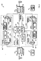
- FIG. 1 shows a computer system 10 that may be used with an illustrative embodiment of the invention for interpreting and processing SELECTION signals transmitted via the known tagged queuing method.
- the computer system 10 includes first and second host computers 14 and 16 interconnected by a SCSI interface 20.
- the SCSI interface 20 includes a main SCSI bus 26 connected to the host computer 14, the auxiliary computer 16 and a first set of SCSI-conforming peripheral devices 22.
- the SCSI interface 20 also includes a auxiliary SCSI bus 28 connected to a second set of five SCSI-conforming peripheral devices 24.
- the SCSI interface 20 also includes a bus extender 30 (hereinafter "bridge 30") for interconnecting the main and auxiliary buses 26, 28.
- bridge 30 bus extender 30
- Host computer 14 is connected to the main bus 26 via a conventional SCSI port 14A.
- host computer 16 is connected to main bus 26 via a host adapter 16A incorporating such a port.
- the interface 20 is responsible for transferring digital signals between the host computers 14, 16 and the auxiliary-bus peripheral devices 24.
- Both computers 14, 16 and each main-bus peripheral device 22 have a unique address on the main bus 26.
- Such addresses are specified in the drawings as ID_0 through ID_7.
- each of the auxiliary-bus peripheral devices 24 has a unique address on the auxiliary bus 28.
- Such addresses also are specified in the drawings as ID_1 through ID_6. ID_0 and ID_7 are reserved as discussed below.
- the bridge 30 also occupies a unique address on each of the main and auxiliary buses 26, 28.
- the bridge 30 has a main bus address of ID_0 and a auxiliary bus address of ID_7.
- the bridge address on the auxiliary bus can be included in the set of auxiliary bus reserved addresses.
- the specific assignment of address IDs can be varied by those skilled in the art, although priority during signal contention on the buses as discussed below should be taken into consideration during ID assignment.
- the particular configuration of the computer system 10 of Figure 1 is for illustrative purposes only. Any combination of computers and main bus peripheral devices can be used in conjunction with the invention as long as at least one initiator is connected to the main bus. For instance, a single computer and seven peripheral devices could be connected to the main bus.
- peripheral devices 22 and 24 can be implemented with any commercially available units adhering to the SCSI standards. As long as such units conform to the SCSI standards, such peripheral devices need not be specifically adapted or modified in terms of either hardware or software for use in conjunction with the invention.
- Data signals may be transmitted from the computers 14 and 16, i.e. initiators, to the peripheral devices 24 on the auxiliary bus 28, i.e. targets, by means of the SELECTION-MESSAGE OUT operation as defined in the SCSI specification.
- targets may re-select an initiator to continue a previously interrupted transmission from such initiator by means of a RESELECTION MESSAGE IN operation, as defined in the SCSI specification.
- FIG. 2 shows a block diagram of an illustrative bridge 30 in accordance with the present invention.
- Bridge 30 includes a main bus 26 and auxiliary-bus transceivers 44, transfer circuits 46, 48 for selectively passing signals between the main bus transceiver 42 and the auxiliary-bus transceiver 44, and control logic 50 for controlling the operation of the other components of the bridge 30.
- the bridge 30 also has a main bus ID-input logic 52, such as a group of switches, which permits a user to manually enter, and then store, a main bus ID identifying the bridge 30.
- the bridge 30 has a clock 30A for providing timing signals, and a power supply 30B.
- Each transceiver 42, 44 has a receiver 56 for receiving signals from the respective originating buses 26, 28, and a driver 58 for sending or asserting signals on the respective target buses 28, 26.
- the transceivers 42, 44 can be either both differential or both single-ended transceivers, or one can be differential and the other single-ended, and, in any event, should conform with the type of signal lines on the bus 26, 28 to which each transceiver 42, 44 is connected.
- Each transfer circuit 46, 48 modifies certain signals, i.e., connection-control signals, received by the transceivers 42, 44, and passes other signals, i.e., message data signals, without modification.
- Each transfer circuit 46, 48 has a demultiplexer 62 ("DEMUX") for receiving the received signals at a data input thereof from its respective transceiver 42 or 44 and, in response to a control signal at a control input thereof, for passing the message data signals onto direct data lines 64 connected to a first output of the DEMUX 62 and passing the connection-control signals 65A or 65B to a converter 66 connected to a second output of the DEMUX 62.
- the direct data lines 64 of the transfer circuit 46, 48 directly couple the message data signal passed by the DEMUX 62 to a multiplexer 68 ("MUX") at a first data input thereof.
- the converters 66 translate the ID and LUN field data of the connection-control signals 65A, 65B into appropriate ID and LUN field data for use on the destination bus 28, 26, in conformance with the address specifications of the SCSI standards.
- the converter 66 then passes the generated ID and LUN field data to the connection-control signal generator 72, which generates connection-control signals 65C, 65D suitable for use on the bus 28, 26 that is to receive the communication.
- the operation of the converters 66 and signal generators 72 of the transfer circuits 46, 48 is described in more detail below and in the previously referenced patent.
- connection-control signals 65C, 65D generated by the signal generator 72 of the transfer circuit 46, 48 are applied to the MUX 68 at a second data input thereof. Responsive to a control signal 74B, 76B at a control input thereof, the MUX 68 passes either the message data signals received over the direct data lines 64, the connection-control signals 65C, 65D, or signals 74C, 76C generated by the control logic 50 (as described hereinafter), to the driver 58 of transreciever 42, 44.
- the control logic 50 includes first and second control logic modules 74, 76, respectively, which, among other functions, (I) monitor (via detect lines 78) signals received by the transceivers 42, 44, and, in response thereto, (ii) control the direction of the transceivers 42, 44 i.e., whether the transceivers are driving or receiving signals using transceiver control lines 82, (iii) control the operation of the DEMUXs 62 and the MUXs 68 by applying thereto appropriate control signals 74A, 74B, and 76A, 76B, and (iv) assert signals 74C, 76C to third data inputs of MUXs 68 to be sent over the target buses.
- first and second control logic modules 74, 76 respectively, which, among other functions, (I) monitor (via detect lines 78) signals received by the transceivers 42, 44, and, in response thereto, (ii) control the direction of the transceivers 42, 44 i.e., whether
- control logic 50 processes SELECTION signals in accordance with the method illustrative in Fig. 3 and may be implemented economically through the use of application-specific integrated circuitry (ASIC).
- controller logic 50 may comprise a programmable logic array or logic devices.
- the transfer circuits 46 and 48 also may be implemented using ASIC.
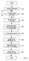
- FIG. 3 is a flow chart illustrating the process for interpreting and processing a SELECTION signal transmitted across the bridge 30 in accordance with the present invention.
- the process begins with step 300 in which an address is reserved on the auxiliary bus for both of the computers 14 and 16.
- the computer 14 will be considered to be the initiator transmitting a SELECTION signal.
- bridge 30 detects the SELECTION signal from the computer 14 (step 302)
- bridge 30 determines the reserved address on the auxiliary bus 28 assigned to the computer 14.
- the bridge 30 modifies the initiator address field in the address portion of the SELECTION signal, thereby producing a converted SELECTION signal, as illustrated by procedural step 304.
- a description of the address portions of a SELECTION signal, including the initiator address field can be found in the SCSI specification.
- the converted SELECTION signal is directed to the intended target.
- the target reads the address information, as illustrated by step 308 and drives a MESSAGE OUT signal on the auxiliary bus in accordance with the SCSI specification as illustrated by step 309.
- the target device then accesses its local memory (not shown) and determines the content, e.g., the command of the message, in the signal also in accordance with the SCSI protocol (step 310).
- the target executes the function specified in the message such as, for example, a write command, thus ending the process.
- Step 312 also is executed in accordance with defined SCSI protocol.
- the process of Figure 3 is effective for use with multiple initiators because the target receives the reserved addresses on the auxiliary bus 28 associated with the initiator device asserting the SELECTION signal. Accordingly, the targets do not receive the address of the bridge 30, as disclosed in the House et al. patent which does not identify which initiator transmitted the SELECTION signal, and, therefore, prohibits utilization of tagged queuing.
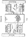
- Fig. 4 illustrates diagrammatically the operation of the bridge 30 during processing of SELECTION signals. More specifically, as shown in Figure 4, first and second main bus connection control signals 122, 124 are received from the main bus 26 by the bridge 30. The bridge 30 uses the data in these signals to generate auxiliary-bus first and second connection control signals 126, 128 to be sent over the auxiliary bus 28.
- the main bus first connection-control signal 122 has an initiator ID field providing the ID of the initiator, e.g. host computer 14, that originated the communication, and a target ID field that provides the ID of the bridge 30 so as to identify the bridge 30 as the intended recipient on the main bus 26 of the communication.
- Converter 66 of transfer circuit 46, in the illustrative embodiment, may include a plurality of writable registers in to which the reserved address for each initiator on the main bus may be written or programmed. As illustrated in Fig. 4, converter 66 converts the initiator ID field of the first connection-control signal 122 into the corresponding reserved address on the auxiliary bus in the form of initiator ID field of the first connection-control signal 126. In the block diagram of Fig. 4 there is no latch necessary to retain the initiator ID field, as was implemented in the bridge disclosed in the House et al. patent.
- the second connection-control signals 124 correspond, for example, to IDENTIFY signals under the SCSI standards, and include a LUN field which, for purposes of the invention, specifies the ultimate target peripheral, e.g. device 24, on the auxiliary bus 28.
- the host computer 14 thus is responsible for identifying both the bridge 30 and the ultimate recipient of the communication in the main bus connection-control signals.
- the converter 66 of the transfer circuit 46 translates the LUN field data of the received second connection-control signal 124 into an address on the auxiliary bus 28 for incorporation into auxiliary bus first connection-control signal 126.
- the converter 66 of circuit 46 also initializes the LUN field data to a predetermined value of zero, for example, for incorporation into a auxiliary-bus second connection-control signal 128.
- the bridge 30 assures that the parity bit 132 provided by the SCSI standards is correct for the generated IDENTIFY message. Specifically, the bridge 30 modifies the parity bit 132 received from the main bus 26 based on whether the change in the value of the LUN field changed the parity for the LUN field i.e., from even to odd, or odd to even, and provides the modified parity bit 134 to the auxiliary bus 28. Accordingly, the bridge 30 changes the parity of the IDENTIFY message based solely on the LUN field data.
- the remaining functions of bus extender 30 during the SELECTION-related phases operate substantially similar to that described in United States Patent 5,274,783.
- FIG. 5 is a flow chart illustrating the process for interpreting and processing a RESELECTION signal to the initiator, i.e., computer 14, transmitted across the bridge 30 in accordance with the present invention.
- the process begins at step 500 in which the bridge 30 is in "monitor mode.” When in this mode, bridge 30 monitors the auxiliary bus 28 for RESELECTION signals directed to any of the reserved addresses i.e., initiator addresses on the auxiliary bus 28, as illustrated by step 502. If such a signal is detected, the initiator address information in the RESELECTION signal is converted to the corresponding address of the initiator on the main bus 26, as illustrated by step 504. Once converted, the bridge then directs or asserts the modified RESELECTION signal on the main bus for detection by the appropriate initiator, e.g. computer 14, in accordance with the SCSI protocol and as illustrated by step 506.
- the appropriate initiator e.g. computer 14, in accordance with the SCSI protocol and as illustrated by step 506.
- Fig. 6 illustrates diagrammatically the operation of the bridge 30 during processing of RESELECTION signals. More specifically, as shown in Figure 6, first and second main bus connection control signals 126, 128 are received from the auxiliary bus 28 by the bridge 30. The bridge 30 uses the data in these signals to generate main bus first and second connection control signals 122, 124 to be sent over the main bus 26.
- the auxiliary bus first connection-control signal 126 has an initiator ID field providing the reserved address associated with ID of the initiator, e.g. host computer 14, that originated the communication, and a target ID field that provides the ID of the target. The bridge responds to the reserved I/D and establishes a connection with the intended recipient of the communication on the main bus 26.
- converter 66 of transfer circuit 48 may include a plurality of writable registers into which the address of the initiator associated with each reserved address on the auxiliary bus may be written or programmed. As illustrated in Fig. 6, converter 66 converts the reserved address, in the form of an initiator ID field, of the first connection-control signal 126 into the corresponding initiator ID on the main bus of the first connection-control signal 126.
- the remaining functions of bus extender 30 during the RESELECTION-related phases operate substantially similar to that described in United States Patent 5,274,783.
- a software implementation of the above described embodiment(s) may comprise a series of computer instructions either fixed on a tangible medium, such as a computer readable media, e.g.
- the medium can be either a tangible medium, including but not limited to optical or analog communications lines, or may be implemented with wireless techniques, including but not limited to microwave, infrared or other transmission techniques.
- the series of computer instructions embodies all or part of the functionality previously described herein with respect to the invention. Those skilled in the art will appreciate that such computer instructions can be written in a number of programming languages for use with many computer architectures or operating systems.
Landscapes
- Engineering & Computer Science (AREA)
- General Engineering & Computer Science (AREA)
- Theoretical Computer Science (AREA)
- Computer Hardware Design (AREA)
- Physics & Mathematics (AREA)
- General Physics & Mathematics (AREA)
- Bus Control (AREA)
Applications Claiming Priority (2)
| Application Number | Priority Date | Filing Date | Title |
|---|---|---|---|
| US08/965,073 US6185651B1 (en) | 1997-11-05 | 1997-11-05 | SCSI bus extender utilizing tagged queuing in a multi-initiator environment |
| US965073 | 1997-11-05 |
Publications (2)
| Publication Number | Publication Date |
|---|---|
| EP0917065A2 true EP0917065A2 (fr) | 1999-05-19 |
| EP0917065A3 EP0917065A3 (fr) | 2000-04-19 |
Family
ID=25509397
Family Applications (1)
| Application Number | Title | Priority Date | Filing Date |
|---|---|---|---|
| EP98308938A Withdrawn EP0917065A3 (fr) | 1997-11-05 | 1998-11-02 | Extension de bus SCSI utilisant des files d'attente marquées dans un environnement multi-initiateur |
Country Status (2)
| Country | Link |
|---|---|
| US (1) | US6185651B1 (fr) |
| EP (1) | EP0917065A3 (fr) |
Cited By (2)
| Publication number | Priority date | Publication date | Assignee | Title |
|---|---|---|---|---|
| GB2382427A (en) * | 2001-09-05 | 2003-05-28 | Hewlett Packard Co | Bus extension to support auxiliary functions |
| US8380938B2 (en) | 2010-02-24 | 2013-02-19 | International Business Machines Corporation | Providing shared access to data storage resources across cluster computing environment boundaries |
Families Citing this family (11)
| Publication number | Priority date | Publication date | Assignee | Title |
|---|---|---|---|---|
| US6430632B1 (en) * | 1999-05-28 | 2002-08-06 | International Business Machines Corporation | Data management small computer system interface (SCSI) extender for extending SCSI communications between SCSI interfaces located relatively far apart |
| US6708242B1 (en) * | 1999-09-10 | 2004-03-16 | Adaptec, Inc. | Methods for addressing extended number of peripheral devices over peripheral bus |
| US6748477B1 (en) * | 2001-03-17 | 2004-06-08 | Hewlett-Packard Development Company, L.P. | Multiple-path interface card for interfacing multiple isolated interfaces to a storage system |
| US6948024B1 (en) * | 2001-05-01 | 2005-09-20 | Adaptec, Inc. | Expander device for isolating bus segments in I/O subsystem |
| US6973520B2 (en) * | 2002-07-11 | 2005-12-06 | International Business Machines Corporation | System and method for providing improved bus utilization via target directed completion |
| US8281084B2 (en) * | 2003-01-13 | 2012-10-02 | Emlilex Design & Manufacturing Corp. | Method and interface for access to memory within a first electronic device by a second electronic device |
| US20040162928A1 (en) * | 2003-02-18 | 2004-08-19 | Hewlett-Packard Development Company, L.P. | High speed multiple ported bus interface reset control system |
| US8484398B2 (en) * | 2004-11-30 | 2013-07-09 | International Business Machines Corporation | Multiple host support for remote expansion apparatus |
| JP2006215954A (ja) * | 2005-02-07 | 2006-08-17 | Hitachi Ltd | ストレージシステム及びストレージ装置のアーカイブ管理方法 |
| US7475163B1 (en) | 2008-01-17 | 2009-01-06 | International Business Machines Corporation | Method and system for resolving SAS timing issues for long-distance SAS extender |
| US8584213B2 (en) | 2010-09-29 | 2013-11-12 | Xerox Corporation | Automated encryption and password protection for downloaded documents |
Family Cites Families (10)
| Publication number | Priority date | Publication date | Assignee | Title |
|---|---|---|---|---|
| US4205373A (en) | 1978-05-22 | 1980-05-27 | Ncr Corporation | System and method for accessing memory connected to different bus and requesting subsystem |
| US5414818A (en) * | 1990-04-06 | 1995-05-09 | Mti Technology Corporation | Method and apparatus for controlling reselection of a bus by overriding a prioritization protocol |
| US5274783A (en) | 1991-06-28 | 1993-12-28 | Digital Equipment Corporation | SCSI interface employing bus extender and auxiliary bus |
| US5708784A (en) * | 1991-11-27 | 1998-01-13 | Emc Corporation | Dual bus computer architecture utilizing distributed arbitrators and method of using same |
| US5528765A (en) * | 1993-03-15 | 1996-06-18 | R. C. Baker & Associates Ltd. | SCSI bus extension system for controlling individual arbitration on interlinked SCSI bus segments |
| US5546546A (en) * | 1994-05-20 | 1996-08-13 | Intel Corporation | Method and apparatus for maintaining transaction ordering and arbitrating in a bus bridge |
| US5564023A (en) * | 1994-06-30 | 1996-10-08 | Adaptec, Inc. | Method for accessing a sequencer control block by a host adapter integrated circuit |
| US5619661A (en) * | 1995-06-05 | 1997-04-08 | Vlsi Technology, Inc. | Dynamic arbitration system and method |
| US5664221A (en) * | 1995-11-14 | 1997-09-02 | Digital Equipment Corporation | System for reconfiguring addresses of SCSI devices via a device address bus independent of the SCSI bus |
| US5778235A (en) * | 1996-02-26 | 1998-07-07 | Robertson; Paul Gordon | Computer system and arbitrator utilizing a bus bridge that avoids livelock |
-
1997
- 1997-11-05 US US08/965,073 patent/US6185651B1/en not_active Expired - Lifetime
-
1998
- 1998-11-02 EP EP98308938A patent/EP0917065A3/fr not_active Withdrawn
Cited By (4)
| Publication number | Priority date | Publication date | Assignee | Title |
|---|---|---|---|---|
| GB2382427A (en) * | 2001-09-05 | 2003-05-28 | Hewlett Packard Co | Bus extension to support auxiliary functions |
| US6813667B2 (en) | 2001-09-05 | 2004-11-02 | Hewlett-Packard Development Company, L.P. | Bus extender and formatter apparatus and methods |
| GB2382427B (en) * | 2001-09-05 | 2005-07-13 | Hewlett Packard Co | Bus extension apparatus and methods |
| US8380938B2 (en) | 2010-02-24 | 2013-02-19 | International Business Machines Corporation | Providing shared access to data storage resources across cluster computing environment boundaries |
Also Published As
| Publication number | Publication date |
|---|---|
| EP0917065A3 (fr) | 2000-04-19 |
| US6185651B1 (en) | 2001-02-06 |
Similar Documents
| Publication | Publication Date | Title |
|---|---|---|
| EP0520838B1 (fr) | Interface SCSI utilisant une extension de bus et un bus auxiliaire | |
| US6557069B1 (en) | Processor-memory bus architecture for supporting multiple processors | |
| USRE44342E1 (en) | Bus architecture employing varying width uni-directional command bus | |
| US6185651B1 (en) | SCSI bus extender utilizing tagged queuing in a multi-initiator environment | |
| US5327431A (en) | Method and apparatus for source routing bridging | |
| US5925120A (en) | Self-contained high speed repeater/lun converter which controls all SCSI operations between the host SCSI bus and local SCSI bus | |
| EP0824239A2 (fr) | Canal secondaire pour bus d'interface de système Fibre Channel | |
| JPS61225946A (ja) | ローカル・エリア・ネツトワークにおいて第1のノードから第2のノードを診断する方法 | |
| JPH1196090A (ja) | I2cバス回路及びバス制御方法 | |
| JPH025665A (ja) | アダプタ | |
| US6510484B1 (en) | Technique for controlling synchronous devices and asynchronous devices connected to an inter-integrated circuit bus (I2C bus) | |
| US5566345A (en) | SCSI bus capacity expansion controller using gating circuits to arbitrate DMA requests from a plurality of disk drives | |
| JPH05502526A (ja) | 擬似同期ハンドシェイキングおよびブロックモードデータ転送を利用したエンハンストvmeバスプロトコル | |
| EP1537700B1 (fr) | Protocole permettant d'acceder a un peripherique local d'un noeud eloigne par l'intermediaire d'infiniband | |
| JP2002123371A (ja) | ディスクアレイ制御装置及びディスクアレイ制御方法 | |
| US7085903B2 (en) | Method, apparatus, and program for improving data mirroring performance in a SCSI topology | |
| CA2392108A1 (fr) | Modele de face arriere de bus vme virtuel tolerant aux pannes | |
| US5987558A (en) | Method and apparatus for resolving over lapping selection and reselection operations of SCSI bus protocols | |
| US5602667A (en) | Extended distance fiber optic interface | |
| KR20140123713A (ko) | 직렬 인터페이스를 통한 디바이스 접근 장치 및 그 방법 | |
| CN100456273C (zh) | PCI-Express通信系统及其通信方法 | |
| JP2000066992A (ja) | バス間接続回路及びコンピュータシステム | |
| JPH01133444A (ja) | システムバス制御装置 | |
| JP3250502B2 (ja) | ディスクアレイ制御装置 | |
| JPH05324545A (ja) | バス制御装置 |
Legal Events
| Date | Code | Title | Description |
|---|---|---|---|
| PUAI | Public reference made under article 153(3) epc to a published international application that has entered the european phase |
Free format text: ORIGINAL CODE: 0009012 |
|
| AK | Designated contracting states |
Kind code of ref document: A2 Designated state(s): AT BE CH CY DE DK ES FI FR GB GR IE IT LI LU MC NL PT SE |
|
| AX | Request for extension of the european patent |
Free format text: AL;LT;LV;MK;RO;SI |
|
| PUAL | Search report despatched |
Free format text: ORIGINAL CODE: 0009013 |
|
| AK | Designated contracting states |
Kind code of ref document: A3 Designated state(s): AT BE CH CY DE DK ES FI FR GB GR IE IT LI LU MC NL PT SE |
|
| AX | Request for extension of the european patent |
Free format text: AL;LT;LV;MK;RO;SI |
|
| RAP1 | Party data changed (applicant data changed or rights of an application transferred) |
Owner name: COMPAQ COMPUTER CORPORATION |
|
| AKX | Designation fees paid | ||
| STAA | Information on the status of an ep patent application or granted ep patent |
Free format text: STATUS: THE APPLICATION IS DEEMED TO BE WITHDRAWN |
|
| 18D | Application deemed to be withdrawn |
Effective date: 20001020 |