EP0917094B1 - Druckersteuerungssystem und -Verfahren - Google Patents
Druckersteuerungssystem und -Verfahren Download PDFInfo
- Publication number
- EP0917094B1 EP0917094B1 EP98309283A EP98309283A EP0917094B1 EP 0917094 B1 EP0917094 B1 EP 0917094B1 EP 98309283 A EP98309283 A EP 98309283A EP 98309283 A EP98309283 A EP 98309283A EP 0917094 B1 EP0917094 B1 EP 0917094B1
- Authority
- EP
- European Patent Office
- Prior art keywords
- print data
- printhead
- printing
- resolution
- Prior art date
- Legal status (The legal status is an assumption and is not a legal conclusion. Google has not performed a legal analysis and makes no representation as to the accuracy of the status listed.)
- Expired - Lifetime
Links
Images




Classifications
-
- G—PHYSICS
- G06—COMPUTING OR CALCULATING; COUNTING
- G06K—GRAPHICAL DATA READING; PRESENTATION OF DATA; RECORD CARRIERS; HANDLING RECORD CARRIERS
- G06K15/00—Arrangements for producing a permanent visual presentation of the output data, e.g. computer output printers
- G06K15/02—Arrangements for producing a permanent visual presentation of the output data, e.g. computer output printers using printers
- G06K15/10—Arrangements for producing a permanent visual presentation of the output data, e.g. computer output printers using printers by matrix printers
-
- G—PHYSICS
- G06—COMPUTING OR CALCULATING; COUNTING
- G06K—GRAPHICAL DATA READING; PRESENTATION OF DATA; RECORD CARRIERS; HANDLING RECORD CARRIERS
- G06K2215/00—Arrangements for producing a permanent visual presentation of the output data
- G06K2215/0002—Handling the output data
- G06K2215/0077—Raster outputting to the print element(s)
Definitions
- This invention relates to a printing apparatus and to a method of controlling printing and, more particularly, to a printing apparatus and such a method for performing printing using a printhead that utilises an ink-jet printing method to discharge ink onto a printing medium.
- a printer for performing printing in accordance with the ink-jet printing method has a printhead, which discharges ink droplets, and an ink tank which supplies ink to the printhead.
- Fig. 5 is a schematic view showing a configuration of a part of an ink discharge portion of a printhead 9.
- the printhead 9 which faces a printing medium 1, such as a recording paper sheet, includes a plurality of ink discharge orifices 10 formed at predetermined intervals in the vertical direction.
- each of the electrothermal transducers 11 e.g. heating resistor
- each of the electrothermal transducers 11 e.g. heating resistor
- the respective ink discharge orifices 10 is driven (heated by sending electric current) in accordance with inputted printing information, thereby causing ink film boiling, and consequently a bubble 12 is formed in the ink.
- the pressure of the formed bubble 12 causes ink to be discharged from the ink discharge orifice 10.
- An ink droplet 13A formed in the ink discharge operation adheres to the printing medium 1, and a predetermined pattern is formed, thereby printing is performed in a dot pattern.
- the electrothermal transducers 11 e.g., heating resistor
- VH heat voltage
- the printhead 9 is equipped with a heat driver 14 for switching on/off electric current to the electrothermal transducers 11, a serial/parallel converter 16 for temporarily storing serially inputted printing information and converting it into parallel data, and a heat signal generator 17 for providing a heat signal to the heat driver 14. Further, a circuit substrate of a printhead controller 29 for providing print data to the serial/parallel converter 16 in synchronization with a clock signal and providing a heat signal to the heat signal generator 17 is installed in a carriage on which the printhead 9 is mounted.
- reference numeral 10A denotes a common liquid chamber for ink connected to the respective nozzles 11A
- reference numeral 13 denotes a liquid channel from an ink tank to the common liquid, chamber 10A.
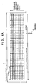
- Such data is stored in a receiving buffer 25a provided in RAM 25 of the printer in the received order as shown in Fig. 6B.
- the nozzles of the printhead 9 are arranged in the direction parallel to the conveyance direction of the printing medium 1. Therefore, as shown in Fig. 6B, when transmitting the data temporarily stored in the receiving buffer 25a to a print buffer 25b, the data is transmitted by an amount corresponding to n ⁇ N-bit addresses at predetermined intervals, thereby divided into blocks of n ⁇ n bits. Then, each block of the divided data is rotated 90 degrees in a data processor 102.
- the above processing is called row-column conversion or H(horizontal)-V(vertical) conversion (hereinafter referred to as "R-C conversion").
- the R-C converted data is transmitted to the printhead 9 in corresponding to the number of nozzles of the printhead via the printhead controller 29.
- the resolution of a printer has been increased to improve the quality of a printed image.
- the resolution of data transmitted from a host to the printer is sometimes lower than that of the printer.
- the resolution of print data may be converted to the resolution of the printer in the printer.
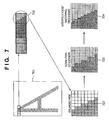
- print data which represents a character pattern 701 as shown in Fig. 7 with a resolution of m ⁇ m dots per unit area ( 8 ⁇ 8 dots in 702 of Fig. 7) is converted into a resolution of 2m ⁇ 2m dots per unit area (16 ⁇ 16 dots in 703 of Fig. 7).
- the resolution conversion of the print data is simply performed as in the manner shown in 703 of Fig. 7, the quality of a printed image remains the same as that of the print data of the original resolution.
- One purpose of representing an image in high resolution is to print smooth curves and smooth slanting lines; therefore, after a resolution of the print data is converted, the print data is further corrected in the printer as shown in 704 of Fig. 7 so as to obtain smooth curves and smooth slanting lines.
- the above operation is called smoothing.
- the simplest smoothing processing is to divide data in the print buffer 25b into blocks of i ⁇ j bits, compare them to patterns of I X j bits prestored in ROM, and apply predetermined corrections to the divided data if the divided data matches one of the patterns.
- processes of comparison and correction are repeatedly performed for each of the plurality of patterns.
- EP-A-0 533 486 describes a recording apparatus for recording an image on a recording medium by scanning a recording head using a scan unit wherein a control unit is provided to control the scan unit to change the scan speed of the recording head according to the resolution of the image data to be recorded.
- a control unit is provided to control the scan unit to change the scan speed of the recording head according to the resolution of the image data to be recorded.
- the controller issues a line feed command for 64 lines to the printer.
- the controller issues a recording speed setting command corresponding to the recording resolution.
- the line feed command is not issued and the printer executes a row-column (vertical-horizontal) conversion to convert recording data stored in the memory in the sub-scan direction to the main scan direction.
- GB-A-2279199 describes an image processing apparatus for a digital copying machine in which binary image data received from other apparatus is divided into binary text/drawing data and binary photographic/graphics data, the binary text/drawing data is converted to multi-value text/drawing data by an edge interpolation filter and the binary photographic/graphics data is converted to multi-value photographic/graphics data by a smoothing filter.
- a mixer then mixes the two sets of multi-value data to provide a single set of multi-value data which is output to a printer to print a multi-gradation image in accordance with the set of multi-value data.
- An embodiment of the present invention provides a printer and printing control method for improving throughput by performing efficient smoothing processing.
- the apparatus may further include a receiving buffer for temporarily storing the print data inputted by the input means; and a print buffer for temporarily storing the print data for printing performed by the printhead; in which case it is preferred to have transmission means for transmitting the print data from the receiving buffer to the print buffer.
- the apparatus further comprises:
- the analyzing means preferably analyzes the print data by a unit corresponding to an area to be printed in one scanning operation of the printhead while the transmission means transmits the print data. Further, the control means may be arranged to cause execution of the row-column conversion means and/or the smoothing means to be skipped in a case where the entire print data corresponding to the area to be printed in the one scanning operation of the printhead does not cause print operation of the printhead.
- the plurality of print elements of the printhead are preferably arranged in the direction perpendicular or diagonal to the scanning direction of the scanning means.
- the apparatus may further comprise determination means for determining whether or not an image to be printed in accordance with the print data inputted by the input means is a natural image or artistic image, wherein the control means performs the control on the basis of a determination result by the determination means.
- the control means is arranged to cause execution of the smoothing means on the print data corresponding to the specific area to be suppressed or skipped.
- the resolution conversion means preferably converts a resolution of the print data inputted by the input means into print data of a higher resolution.
- the printhead is preferably an ink-jet printhead which performs printing by discharging ink, and the printhead has an electrothermal transducer for generating thermal energy to be applied to ink for discharging the ink using the thermal energy.
- a printing apparatus embodying the invention is particularly advantageous since, when there is no print data which causes print operation in a predetermined amount of data or when input print data is of a natural picture or artistic picture, row-column conversion and smoothing processing are skipped, thus, it is possible to perform efficient row-column conversion and smoothing processing. Accordingly, it is possible to improve throughput in printing processing.
- Fig. 1 is an external perspective view showing the construction of a printer, which is a typical embodiment of the present invention, equipped with printheads for performing printing in accordance with ink-jet printing method.
- the printer includes convey rollers 2, 3, which are arranged above and below a printing area at which printing paper (or other printing medium such as a plastic sheet) 1 is printed on, for conveying the printing paper 1 in the direction of an arrow A, a sheet feed motor 4 for driving the convey rollers 2, 3, a guide shaft 5 situated between the convey rollers 2 and 3 and provided in parallel with the rotary shafts of the convey rollers 2, 3, a carriage 6 moved back and forth (in the directions of arrow B) along the guide shaft 5, a carriage motor 7 for moving the carriage 6, and a belt 8 for transmitting the driving force of the carriage motor 7 to the carriage 6.
- convey rollers 2, 3 which are arranged above and below a printing area at which printing paper (or other printing medium such as a plastic sheet) 1 is printed on, for conveying the printing paper 1 in the direction of an arrow A
- a sheet feed motor 4 for driving the convey rollers 2, 3
- a guide shaft 5 situated between the convey rollers 2 and 3 and provided in parallel with the rotary shafts of the convey rollers
- printheads 9A ⁇ 9D which perform printing by discharging ink droplets in accordance with an ink-jet printing method.
- the printheads 9A ⁇ 9D have the identical structure as shown in Fig. 5, when the four printheads are referred to collectively, the term "printhead 9" will be used.
- the printhead 9 which is for printing color images, comprises the four printheads, namely the printhead (Bk-head) 9A, the printhead (C-head) 9B, the printhead (M-head) 9C and the printhead (Y-head) 9D arranged along the scanning direction of the carriage 6 and provided so as to correspond to inks of the colors black (Bk), cyan (C) , magenta (M), and yellow (Y), respectively.
- a plurality e.g.
- a control panel 64 mounted on the external case (not shown) of the printer is provided with keys such as an online/offline changeover key 60A, a line feed key 60B, a printing mode changeover key 60C and a reset key 60D, LED lamps such as an alarm lamp 61A and power supply lamp 61B, and an LCD 65 for displaying various messages.
- keys such as an online/offline changeover key 60A, a line feed key 60B, a printing mode changeover key 60C and a reset key 60D, LED lamps such as an alarm lamp 61A and power supply lamp 61B, and an LCD 65 for displaying various messages.
- the printer further includes an ink tank 92 which stores ink for printing a desired image on the printing paper.
- the ink tank 92 includes four ink compartments which store inks of four colors [black (Bk) , cyan (C) , magenta (M) and yellow (Y)] corresponding to the printheads 9A, 9B, 9C and 9D, respectively.
- reference numeral 202 denotes a platen.
- a controller which includes the printer CPU and accompanying components such as a ROM and RAM receives command signals and data signals (printing information) from a host computer (referred to as a "host” below), drives various motors based upon these signals and applies driving power (heating power) to electrothermal transducers (heaters) included in the printheads 9A ⁇ 9D, whereby the transducers are energized.
- a host referred to as a "host” below
- Fig. 2 is a block diagram showing the configuration of control circuitry in the printer illustrated in Fig. 1.
- the control circuitry includes a CPU 21 of microprocessor form connected to a host 100 via an interface 22.
- the CPU 21 accesses a ROM 24 storing a control program, an EEPROM 23 storing an updatable control program, a processing program and data representing various constants and a RAM 25 for storing a command signal and a printing information signal received from the host 100 via an interface 22, and controls the printing operation based upon information that has been stored in these memories.
- the processing executed in accordance with the above processing program includes a process of transmitting raster print data, received via the interface 22 and stored in a receiving buffer, to a print buffer of the RAM 25, a process of converting the order of the print data stored in the print buffer in consideration of the arrangement of print elements of the printhead 9 (R-C conversion), a process of transmitting print data bitmapped in a work area of the RAM 25 to the print head controller 29, a process of resolution conversion to be performed on low resolution print data (e.g., 300dpi) received from the host 100 and bitmapped in the work area of the RAM 25 (e.g, 300dpi to 600dpi), and a smoothing-process of removing jaggedness.
- R-C conversion converting the order of the print data stored in the print buffer in consideration of the arrangement of print elements of the printhead 9
- the CPU 21 operates the carriage motor 7 via an output port 26 and carriage motor control circuit 42 to thereby move the carriage 6, and operate the sheet feed motor 4 via the output port 26 and sheet feed motor control circuit 44 to thereby operate a conveyance mechanism which includes the convey rollers 2, 3. Further, the CPU 21 drives the printheads 9A ⁇ 9D via a printhead control circuit 29 based upon the printing information that has been stored in the RAM 25, thereby making it possible to print a desired image on the printing paper 1.
- a power supply circuit 28 outputs a logic drive voltage Vcc (e.g. 5 V) for operating the CPU 21, a voltage Vm (e.g.. 30 V) for driving the various motors, a heating voltage Vh (e.g. 25 V) for driving the printhead 9, and a back-up voltage VDDH for protecting the printhead 9.
- Vcc logic drive voltage
- Vm voltage
- Vh heating voltage
- VDDH back-up voltage
- Signals from the keys 60A - 60D are sent to the CPU 21 via an input port 32.
- a buzzer generation control circuit 62 via an output port 36
- a buzzer 63 make sounds.
- an instruction from the CPU 21 is sent to a display control circuit 66 via the output port 36, a message is displayed on the LCD 65.
- reference numeral 33 denotes a DIP switch, provided on, e.g., the bottom part of the exterior of the printer, for transferring its output to the CPU 21 via the input port 32; 70, a CPU bus for connecting a variety of configuring elements to each other; 80, a paper-width sensor, provided in the printhead 9, for detecting width of the printing medium 1; 81, an A/D converter for converting an analog signal from the paper-width sensor 80 into a digital signal; and 102, the data processor.
- the CPU bus 70 includes an address bus used for transmitting/receiving an address for data access and a data bus used for data transmission.
- the receiving buffer and the print buffer are provided in the RAM 25, and the CPU 21 uses the data processor 102 to perform R-C conversion, resolution conversion, and smoothing processing while accessing to the receiving buffer, print buffer and work area, provided in the RAM 25.
- Fig. 3 is a block diagram illustrating a configuration of the data processor 102 and its configuring elements, and showing relationship with the receiving buffer, the print buffer, and the CPU 21.
- the data processor 102 includes a data processing skip detector 102a for determining whether to perform or skip the subsequent R-C conversion and smoothing processing on the basis of the input print data, an R-C conversion processor 102b, and a smoothing processor 102c.
- a determination result by the data processing skip detector 102a is inputted to the R-C conversion processor 102b and the smoothing processor 102c as a determination result signal.
- the receiving buffer 25a and the print buffer 25b, both provided in the RAM 25, the data processing skip detector 102a, the R-C conversion processor 102b and the smoothing processor 102c are connected to the CPU 21 and to each other via the address bus 70a and the data bus 70b.
- a detection timing signal is transmitted from the receiving buffer 25a to the data processing skip detector 102a. Further, when the R-C conversion processor 102b and the smoothing processor 102c start respective processes, they transmit process start signals to the data processing skip detector 102a.
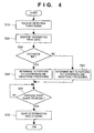
- step S10 when transmitting print data from the receiving buffer 25a to the print buffer 25b, the data processing skip detector 102a receives a detection timing signal from the receiving buffer 25a. Then, the data processing skip detector 102a monitors the transmitted print data in step S20, and checks whether or not data which does not cause ink discharge from the printhead 9 (called "0" data) is included in the transmitted print data corresponding to, e.g., an area to be printed in one scanning operation of the printhead 9 (one scanning printing area) in step S30.
- step S40 it is determined that R-C conversion and smoothing processing are to be performed in the area, and determination information indicative of it is stored.
- step S50 it is determined that R-C conversion and smoothing processing are not to be performed for the area, and determination information indicative of it is stored.
- step S60 the data processing skip detector 102a waits a process start signal or signals from the R-C conversion processor 102b and/or the smoothing processor 102c.
- step S70 the data processing skip detector 102a transmits a determination result signal indicative of determination information obtained either in step S40 or S50 to the R-C conversion processor 102b and/or the smoothing processor 102c, and the process is completed.
- the R-C conversion processor 102b and/or the smoothing processor 102c executes R-C conversion and/or smoothing processing in accordance with the received determination result signal. If the determination result signal indicates not to perform processing, then processing is not performed in the R-C conversion processor 102b and/or the smoothing processor 102c. In other words, the R-C conversion processor 102b and/or the smoothing processor 102c performs processing only when execution of processing is designated.
- execution of R-C conversion and smoothing processing is controlled in accordance with print data; accordingly, the processings are not performed in vain, thereby it is possible to prevent a decrease in throughput caused by performing unnecessary R-C conversion and smoothing processing. In this manner, unnecessary load on the CPU is removed, which contributes to an increase in throughput in printing operation.
- a predetermined area e.g., one scanning printing area
- R-C conversion and the smoothing processing are omitted; however, the present invention is not limited to this, and it is possible to control to skip smoothing processing when all the print data in a predetermined area is a natural picture or artistic picture, for instance.
- the determination of an image in a specific area being a natural picture or artistic picture is performed on the basis of a command transmitted from a host, or by analyzing continuity of density values of consecutive pixels or density distribution of an area on the basis of print data transmitted from the host and judging whether or not the print data is of a natural picture or artistic picture on the basis of the continuity/discontinuity and the density distribution, since densities of consecutive pixels of a natural picture or artistic picture change continuously or density distribution of an area is broad.
- the DIP switch 33 may be used for instructing whether the determination is based on the command from the host or data analysis in a printer.
- a droplet discharged from the printhead is explained as an ink droplet
- liquid stored in the ink tank is explained as ink in the above embodiment, however, the present invention is not limited to ink.
- processed liquid to be discharged toward a printing medium for improving stability, water-resistance, and quality of an image may be stored in the ink tank.
- the execution of R-C conversion processing and smoothing processing is controlled based on the content of input print data.
- the present invention includes a case where either the R-C conversion processing or the smoothing processing may be skipped based on the content of print data. In this case, if the high load processing is skipped, this skip greatly contributes to improving apparatus' throughput. Also, in a printing apparatus which employs a full-line type printhead in which a plurality of printing elements are arrayed along with an entire width of a printing medium, it is not necessary to perform the above-described R-C conversion processing. In this printing apparatus, only the smoothing may be skipped based on printing data.
- a printer which comprises means (e.g., an electrothermal transducer, laser beam generator, and the like) for generating heat energy as energy utilized upon execution of ink discharge, and causes a change in state of an ink by the heat energy, among the ink-jet printers.
- means e.g., an electrothermal transducer, laser beam generator, and the like
- heat energy as energy utilized upon execution of ink discharge
- the system is effective because, by applying at least one driving signal, which corresponds to printing information and gives a rapid temperature rise exceeding film boiling, to each of electrothermal transducers arranged in correspondence with a sheet or liquid channels holding a liquid (ink) , heat energy is generated by the electrothermal transducer to effect film boiling on the heat acting surface of the printhead, and consequently, a bubble can be formed in the liquid (ink) in one-to-one correspondence with the driving signal.
- the driving signal is applied as a pulse signal, the growth and shrinkage of the bubble can be attained instantly and adequately to achieve discharge of the liquid (ink) with the particularly high response characteristics.
- signals disclosed in U. S. Patent Nos. 4, 463, 359 and 4, 345, 262 are suitable. Note that further excellent printing can be performed by using the conditions described in U.S. Patent No. 4,313,124 of the invention which relates to the temperature rise rate of the heat acting surface.
- the arrangement using U.S. Patent Nos. 4,558,333 and 4,459,600 which disclose the arrangement having a heat acting portion arranged in a flexed region is also included in the present invention.
- the present invention can be effectively applied to an arrangement based on Japanese Patent Laid-Open No. 59-123670 which discloses the arrangement using a slot common to a plurality of electrothermal transducers as a discharge portion of the electrothermal transducers, or Japanese Patent Laid-Open No. 59-138461 which discloses the arrangement having an opening for absorbing a pressure wave of heat energy in correspondence with a discharge portion.
- a full line type printhead having a length corresponding to the width of a maximum printing medium which can be printed by the printer
- either the arrangement which satisfies the full-line length by combining a plurality of printheads as disclosed in the above specification or the arrangement as a single printhead obtained by forming printheads integrally can be used.
- an exchangeable chip type printhead as described in the above embodiment, which can be electrically connected to the apparatus main unit and can receive an ink from the apparatus main unit upon being mounted on the apparatus main unit but also a cartridge type printhead in which an ink tank is integrally arranged on the printhead itself can be applicable to the present invention.
- recovery means for the printhead, preliminary auxiliary means, and the like provided as an arrangement of the printer of the present invention since the printing operation can be further stabilized.
- examples of such means include, for the printhead, capping means, cleaning means, pressurization or suction means, and preliminary heating means using electrothermal transducers, another heating element, or a combination thereof. It is also effective for stable printing to provide a preliminary discharge mode which performs discharge independently of printing.
- a printing mode of the printer not only a printing mode using only a primary color such as black or the like, but also at least one of a multi-color mode using a plurality of different colors or a full-color mode achieved by color mixing can be implemented in the printer either by using an integrated printhead or by combining a plurality of printheads.
- the ink is a liquid.
- the present invention may employ an ink which is solid at room temperature or less and softens or liquefies at room temperature, or an ink which liquefies upon application of a use printing signal, since it is a general practice to perform temperature control of the ink itself within a range from 30°C to 70°C in the ink-jet system, so that the ink viscosity can fall within a stable discharge range.
- an ink which is solid in a non-use state and liquefies upon heating may be used.
- an ink which liquefies upon application of heat energy according to a printing signal and is discharged in a liquid state, an ink which begins to solidify when it reaches a printing medium, or the like, is applicable to the present invention.
- an ink may be situated opposite electrothermal transducers while being held in a liquid or solid state in recess portions of a porous sheet or through holes, as described in Japanese Patent Laid-Open No. 54-56847 or 60-71260.
- the above-mentioned film boiling system is most effective for the above-mentioned inks.
- the ink-jet printer of the present invention may be used in the form of a copying machine combined with a reader, and the like, or a facsimile apparatus having a transmission/reception function in addition to an image output terminal of an information processing equipment such as a computer.
- the present invention can be applied to a system constituted by a plurality of devices (e.g., host computer, interface, reader, printer) or to an apparatus comprising a single device (e.g., copying machine, facsimile machine). Furthermore, it goes without saying that the invention is applicable also to a case where the object of the present invention can be achieved by supplying a memory medium which stores program codes for realizing the functions of the aforesaid embodiment to a system or an apparatus, reading the program codes with a computer (e.g., CPU, MPU) of the system or apparatus from the storage medium, then executing the program.
- a computer e.g., CPU, MPU
- the program codes read from the storage medium realize the functions according to the embodiments, and the storage medium storing the program codes constitutes the invention.
- the storage medium such as a floppy disk, a hard disk, an optical disk, a magneto-optical disk, CD-ROM, CD-R, a magnetic tape, a non-volatile type memory card, and ROM can be used for supplying the program codes.
- the present invention includes a case where an OS (operating system) or the like working on the computer performs a part or entire processes in accordance with designations of the program codes and realizes functions according to the above embodiments.
- the present invention also includes a case where, after the program codes read from the storage medium are written in a function expansion card which is inserted into the computer or in a memory provided in a function expansion unit which is connected to the computer, CPU or the like contained in the function expansion card or unit performs a part or entire process in accordance with designations of the program codes and realizes functions of the above embodiments.
Landscapes
- Physics & Mathematics (AREA)
- Engineering & Computer Science (AREA)
- Mathematical Physics (AREA)
- General Engineering & Computer Science (AREA)
- General Physics & Mathematics (AREA)
- Theoretical Computer Science (AREA)
- Ink Jet (AREA)
- Dot-Matrix Printers And Others (AREA)
- Facsimile Image Signal Circuits (AREA)
- Record Information Processing For Printing (AREA)
- Editing Of Facsimile Originals (AREA)
Claims (19)
- Druckvorrichtung zum Drucken auf ein Druckmedium durch Verwendung eines Druckkopfs (9) mit einer Vielzahl von Druckelementen, mit:einer Eingabeeinrichtung (22) zum Eingeben von Druckdaten mit einer vorbestimmten Auflösung;einer Auflösungsumwandlungseinrichtung (102) zum Umwandeln der Auflösung der Druckdaten, um auflösungsumgewandelte Druckdaten zu erzeugen;einer Glättungseinrichtung (102c) zum Anwenden einer Glättungsverarbeitung auf auflösungsumgewandelte Druckdaten; undeiner Zeilen-Spalten-Umwandlungseinrichtung (102b) zum Umwandeln einer Ordnung der von der Eingabeeinrichtung eingegebenen Druckdaten in die Richtung einer Anordnung der Druckelemente des Druckkopfs;gekennzeichnet durch:eine Analyseeinrichtung (102a) zum Analysieren der Druckdaten in Druckdateneinheiten, wobei jede eine vorbestimmte Menge von einem vorbestimmten Druckbereich entsprechenden Druckdaten aufweist, um zu bestimmen, ob die vorbestimmte Menge von Druckdaten einen Druckbetrieb des Druckkopfs verursachen wird oder nicht; undeine Steuerungseinrichtung (21) zum Steuern eines Betriebs von mindestens einer der Zeilen-Spalten-Umwandlungseinrichtung (102b) und der Glättungseinrichtung (102a) in Übereinstimmung mit dem Ergebnis der Analyse durch die Analyseeinrichtung,wobei die Zeilen-Spalten-Umwandlungseinrichtung (102b) eingerichtet ist, die Ordnung der Druckdaten in Einheiten der vorbestimmten Menge von Druckdaten umzuwandeln, und die Steuerungseinrichtung (21) eingerichtet ist, einen Steuerungsbetrieb durchzuführen, um den Betrieb von der mindestens einen der Zeilen-Spalten-Umwandlungseinrichtung (102b) und der Glättungseinrichtung (102a) bezüglich der vorbestimmten Menge von Druckdaten in einem Fall zu unterdrücken, in dem die Analyseeinrichtung bestimmt, dass die vorbestimmte Menge von Druckdaten keinen Druckbetrieb des Druckkopfs verursachen wird.
- Druckvorrichtung gemäß Anspruch 1, zusätzlich mit:einer Abtasteinrichtung (6, 7, 8) zum Hin- und Her-Abtastbewegen des Druckkopfs; undeiner Beförderungseinrichtung (2, 34) zum Befördern des Druckmediums in einer Richtung senkrecht zu der Abtastrichtung der Abtasteinrichtung.
- Vorrichtung gemäß Anspruch 2, wobei die Steuerungseinrichtung (21) eingerichtet ist, den Steuerungsbetrieb durchzuführen, um den Betrieb der Glättungseinrichtung (102c) in einem Fall zu unterdrücken, in dem die Gesamtheit der Druckdaten, die dem in dem einen Abtastbetrieb des Druckkopfs (9) zu druckenden Bereich entspricht, keinen Druckbetrieb des Druckkopfs verursachen wird.
- Vorrichtung gemäß Anspruch 1, 2 oder 3, wobei die Steuerungseinrichtung (21) eingerichtet ist, den Steuerungsbetrieb durchzuführen, um den Betrieb der Zeilen-Spalten-Umwandlungseinrichtung (102b) und der Glättungseinrichtung (102c) in einem Fall zu unterdrücken, in dem die Analyseeinrichtung (102a) bestimmt, dass die vorbestimmte Menge von Druckdaten keinen Druckbetrieb des Druckkopfs verursachen wird.
- Vorrichtung gemäß Anspruch 2, wobei die Steuerungseinrichtung (21) eingerichtet ist, den Steuerungsbetrieb durchzuführen, um den Betrieb von mindestens einer der Zeilen-Spalten-Umwandlungseinrichtung (102b) und der Glättungseinrichtung (102c) in einem Fall zu unterdrücken, in dem die gesamten Druckdaten, die dem in dem einen Abtastbetrieb des Druckkopfs (9) zu druckenden Bereich entsprechen, keinen Druckbetrieb des Druckkopfs verursachen werden.
- Vorrichtung gemäß einem der vorstehenden Ansprüche, zusätzlich mit:einem Empfangspuffer (25a) zum vorübergehenden Speichern
der von der Eingabeeinrichtung (22) eingegebenen Druckdaten; undeinem Druckpuffer (25b) zum vorübergehenden Speichern der Druckdaten zum Drucken, das durch den Druckkopf (9) durchzuführen ist. - Vorrichtung gemäß Anspruch 6, zusätzlich mit einer Übermittlungseinrichtung (70a, 70b) zum Übermitteln der Druckdaten von dem Empfangspuffer (25a) zu dem Druckpuffer (25b).
- Vorrichtung gemäß Anspruch 7, wenn abhängig von Anspruch 2, wobei die Analyseeinrichtung (102a) eingerichtet ist, die Druckdaten in Einheiten zu analysieren, die einem in einem Abtastbetrieb des Druckkopfs (9) zu druckenden Bereich entsprechen, während die Übermittlungseinrichtung (70a, 70b) die Druckdaten übermittelt.
- Vorrichtung gemäß einem der vorstehenden Ansprüche, zusätzlich mit einer Bestimmungseinrichtung zum Bestimmen, ob ein Bild, das in Übereinstimmung mit den von der Eingabeeinrichtung (22) eingegebenen Druckdaten zu drucken ist, ein natürliches oder ein künstliches Bild ist oder nicht, wobei die Steuerungseinrichtung (21) eingerichtet ist, den Steuerungsbetrieb auf der Grundlage eines Bestimmungsergebnisses von der Bestimmungseinrichtung durchzuführen.
- Vorrichtung gemäß Anspruch 6, wobei die Steuerungseinrichtung (21) eingerichtet ist, den Steuerungsbetrieb durchzuführen, um den Betrieb der Glättungseinrichtung (102c) bezüglich der Druckdaten die einem spezifischen Bereich entsprechen, in einem Fall zu unterdrücken, in dem die Bestimmungseinrichtung bestimmt, dass in dem spezifischen Bereich ein natürliches oder ein künstliches Bild zu drucken ist.
- Vorrichtung gemäß einem der Ansprüche 2 bis 5, wobei die Abtasteinrichtung (6, 7, 8) zum Abtastbewegen des Druckkopfs eingerichtet ist, so dass die Vielzahl von Druckelementen des Druckkopfs in einer Richtung senkrecht oder diagonal zu der Abtastrichtung der Abtasteinrichtung (6, 7, 8) angeordnet ist.
- Vorrichtung gemäß einem der vorstehenden Ansprüche, wobei die Auflösungsumwandlungseinrichtung (102) eingerichtet ist, die Auflösung der von der Eingabeeinrichtung (22) eingegebenen Druckdaten in Druckdaten einer höheren Auflösung umzuwandeln.
- Vorrichtung gemäß einem der vorstehenden Ansprüche, zusätzlich mit einem Tintenstrahldruckkopf (9) als der Druckkopf, der eingerichtet ist, Drucken durch Freisetzen von Tinte durchzuführen.
- Vorrichtung gemäß Anspruch 13, wobei der Druckkopf (9) einen elektro-thermischen Wandler zum Erzeugen thermischer Energie hat, um Tintenfreisetzung zu verursachen.
- Verfahren zum Steuern eines Druckens auf ein Druckmedium unter Verwendung eines Druckkopfs (9) mit einer Vielzahl von Druckelementen, wobei das Verfahren aufweist:einen Eingabeschritt zum Eingeben von Druckdaten mit einer vorbestimmten Auflösung;einen Auflösungsumwandlungsschritt zum Umwandeln der Auflösung der Druckdaten, um auflösungsumgewandelte Druckdaten zu erzeugen;einen Glättungsschritt zum Anwenden einer Glättungsverarbeitung auf auflösungsumgewandelte Druckdaten;einen Zeilen-Spalten-Umwandlungsschritt zum Umwandeln einer Ordnung der eingegebenen Druckdaten in die Richtung einer Anordnung der Druckelemente des Druckkopfs;einen Analyseschritt zum Analysieren der Druckdaten in Druckdateneinheiten, wobei jede eine vorbestimmte Menge von Druckdaten aufweist, die einem vorbestimmten Druckbereich entsprechen, um zu bestimmen, ob die vorbestimmte Menge von Druckdaten einen Druckbetrieb des Druckkopfs verursachen wird oder nicht; undeinen Steuerungsschritt zum Steuern der Anwendung von mindestens einem des Zeilen-Spalten-Umwandlungs- und des Glättungsverarbeitungsschritts in Übereinstimmung mit dem Ergebnis der Analyse in dem Analyseschritt, wobei der Zeilen-Spalten-Umwandlungsschritt die Ordnung der Druckdaten in Einheiten der vorbestimmten Menge von Druckdaten umwandelt und der Steuerungsschritt die Anwendung von dem mindestens einen des Zeilen-Spalten-Umwandlungs- und des Glättungsverarbeitungsschritts bezüglich der vorbestimmten Menge von Druckdaten in einem Fall unterdrückt, in dem der Analyseschritt bestimmt, dass die vorbestimmte Menge von Druckdaten keinen Druckbetrieb des Druckkopfs verursachen wird.
- Verfahren gemäß Anspruch 15, wobei der Druckkopf durch Hin- und Her-Abtastbewegen des Druckkopfs und durch Befördern des Druckmediums in eine Richtung senkrecht zu der Abtastrichtung der Abtasteinrichtung zwischen Abtastungen ermöglicht, dass die Druckdaten gedruckt werden.
- Verfahren gemäß Anspruch 16, wobei der Steuerungsschritt den Steuerungsbetrieb durchführt, um den Glättungsbetrieb in einem Fall zu unterdrücken, in dem die Gesamtheit der Druckdaten, die dem in dem einen Abtastbetrieb des Druckkopfs (9) zu druckenden Bereich entspricht, keinen Druckbetrieb des Druckkopfs verursachen wird.
- Verfahren gemäß Anspruch 15, 16 oder 17, wobei der Steuerungsschritt (21) den Steuerungsbetrieb durchführt, um den Zeilen-Spalten-Umwandlungs- und den Glättungsbetrieb in einem Fall zu unterdrücken, in dem bestimmt wird, dass die vorbestimmte Menge von Druckdaten keinen Druckbetrieb des Druckkopfs verursachen wird.
- Verfahren gemäß Anspruch 15, 16, 17 oder 18, zusätzlich mit einem Bestimmungsschritt zum Bestimmen, ob ein Bild, das in Übereinstimmung mit den in dem Eingabeschritt eingegebenen Druckdaten zu drucken ist, ein natürliches oder ein künstliches Bild ist oder nicht, wobei der Steuerungsschritt den Steuerungsbetrieb auf der Grundlage eines Bestimmungsergebnisses von dem Bestimmungsschritt durchführt.
Applications Claiming Priority (3)
| Application Number | Priority Date | Filing Date | Title |
|---|---|---|---|
| JP31198497A JP3517570B2 (ja) | 1997-11-13 | 1997-11-13 | 記録装置及び記録制御方法 |
| JP311984/97 | 1997-11-13 | ||
| JP31198497 | 1997-11-13 |
Publications (3)
| Publication Number | Publication Date |
|---|---|
| EP0917094A2 EP0917094A2 (de) | 1999-05-19 |
| EP0917094A3 EP0917094A3 (de) | 2000-05-17 |
| EP0917094B1 true EP0917094B1 (de) | 2006-03-29 |
Family
ID=18023807
Family Applications (1)
| Application Number | Title | Priority Date | Filing Date |
|---|---|---|---|
| EP98309283A Expired - Lifetime EP0917094B1 (de) | 1997-11-13 | 1998-11-12 | Druckersteuerungssystem und -Verfahren |
Country Status (4)
| Country | Link |
|---|---|
| US (1) | US6328401B1 (de) |
| EP (1) | EP0917094B1 (de) |
| JP (1) | JP3517570B2 (de) |
| DE (1) | DE69834014T2 (de) |
Families Citing this family (2)
| Publication number | Priority date | Publication date | Assignee | Title |
|---|---|---|---|---|
| EP1176550A1 (de) * | 2000-07-27 | 2002-01-30 | STMicroelectronics S.r.l. | Verfahren zum Speichern von Daten in einem Speicher |
| US6719388B2 (en) * | 2002-01-16 | 2004-04-13 | Xerox Corporation | Fail-safe circuit for dynamic smartpower integrated circuits |
Family Cites Families (16)
| Publication number | Priority date | Publication date | Assignee | Title |
|---|---|---|---|---|
| CA1127227A (en) | 1977-10-03 | 1982-07-06 | Ichiro Endo | Liquid jet recording process and apparatus therefor |
| JPS5936879B2 (ja) | 1977-10-14 | 1984-09-06 | キヤノン株式会社 | 熱転写記録用媒体 |
| US4330787A (en) | 1978-10-31 | 1982-05-18 | Canon Kabushiki Kaisha | Liquid jet recording device |
| US4345262A (en) | 1979-02-19 | 1982-08-17 | Canon Kabushiki Kaisha | Ink jet recording method |
| US4463359A (en) | 1979-04-02 | 1984-07-31 | Canon Kabushiki Kaisha | Droplet generating method and apparatus thereof |
| US4313124A (en) | 1979-05-18 | 1982-01-26 | Canon Kabushiki Kaisha | Liquid jet recording process and liquid jet recording head |
| US4558333A (en) | 1981-07-09 | 1985-12-10 | Canon Kabushiki Kaisha | Liquid jet recording head |
| JPS59123670A (ja) | 1982-12-28 | 1984-07-17 | Canon Inc | インクジエツトヘツド |
| JPS59138461A (ja) | 1983-01-28 | 1984-08-08 | Canon Inc | 液体噴射記録装置 |
| JPS6071260A (ja) | 1983-09-28 | 1985-04-23 | Erumu:Kk | 記録装置 |
| JPS60169893A (ja) * | 1984-02-15 | 1985-09-03 | シチズン時計株式会社 | ビツトパタ−ン変換装置 |
| JP3295107B2 (ja) * | 1991-07-30 | 2002-06-24 | キヤノン株式会社 | 画像記録装置 |
| DE69221410T2 (de) * | 1991-09-19 | 1997-12-11 | Canon Kk | Serienaufzeichnungsverfahren mit Möglichkeit zur Änderung der Auflösung |
| US5574832A (en) | 1992-08-03 | 1996-11-12 | Hewlett-Packard Corporation | Double axis dot depletion for 600 DPI edge acuity with 300 DPI print cartridge |
| DE69324418T2 (de) * | 1992-08-26 | 1999-08-05 | Hewlett Packard Co | Verfahren und Vorrichtung zur Kantenglättung in Pixelbildern |
| GB2279199B (en) * | 1993-06-18 | 1997-07-30 | Ricoh Kk | Image processing apparatus |
-
1997
- 1997-11-13 JP JP31198497A patent/JP3517570B2/ja not_active Expired - Fee Related
-
1998
- 1998-11-12 DE DE69834014T patent/DE69834014T2/de not_active Expired - Fee Related
- 1998-11-12 US US09/190,101 patent/US6328401B1/en not_active Expired - Fee Related
- 1998-11-12 EP EP98309283A patent/EP0917094B1/de not_active Expired - Lifetime
Also Published As
| Publication number | Publication date |
|---|---|
| DE69834014D1 (de) | 2006-05-18 |
| JPH11138906A (ja) | 1999-05-25 |
| EP0917094A3 (de) | 2000-05-17 |
| EP0917094A2 (de) | 1999-05-19 |
| JP3517570B2 (ja) | 2004-04-12 |
| US6328401B1 (en) | 2001-12-11 |
| DE69834014T2 (de) | 2006-09-14 |
Similar Documents
| Publication | Publication Date | Title |
|---|---|---|
| EP0700786B2 (de) | Bildaufzeichnungsgerät | |
| US6352327B1 (en) | Printing apparatus and print control method | |
| EP1396345B1 (de) | Verfahren, System und Gerät zum Tintenstrahldrucken, Verfahren und Programm zur Erzeugung von Druckdaten, und Druckersteuerung | |
| US6102520A (en) | Recording apparatus with ink spot volume regulation | |
| EP1264697B1 (de) | Bilddruckgerät mit Steuerverfahren dafür, Speichermedium und Programm | |
| US7758154B2 (en) | Inkjet printing apparatus and inkjet printing method | |
| JP2002292906A (ja) | 画素ブロック単位で濃淡インクによる階調再現を行う印刷 | |
| US7207644B2 (en) | Printing apparatus and printing control method for controlling the number of printing elements used in printing | |
| JP3667118B2 (ja) | 記録装置および記録方法 | |
| US6467866B1 (en) | Print control method and apparatus, and printing apparatus using the same | |
| US6175424B1 (en) | Image processing apparatus and image processing method | |
| JP3152846B2 (ja) | インクジェット記録装置および方法 | |
| EP0593283B1 (de) | Bild-Druckverfahren und Vorrichtung dafür | |
| US7315393B2 (en) | Printing system, printer driver, and printing method | |
| EP1355264B1 (de) | Druckgerät und Druckverfahren | |
| EP0917094B1 (de) | Druckersteuerungssystem und -Verfahren | |
| US5629771A (en) | Recording apparatus featuring recording elements disposed in a line wherein the line is slanted relative to a subscanning direction and a method of using same | |
| US6116711A (en) | Printer and printing control method according to detected amount of memory | |
| EP0855278A2 (de) | Drucken unter Verwendung eines Tintenstrahldruckers | |
| JP3179674B2 (ja) | 画像記録方法とその装置 | |
| EP0856985B1 (de) | Druckgerät und Drucksteuerverfahren | |
| US7206095B2 (en) | Printing apparatus and method | |
| US20020126163A1 (en) | Image printing apparatus and method | |
| JP2746742B2 (ja) | インクジェット記録装置 | |
| JPH10129011A (ja) | カラー画像と白黒画像の打ち分け記録方法および記録装置 |
Legal Events
| Date | Code | Title | Description |
|---|---|---|---|
| PUAI | Public reference made under article 153(3) epc to a published international application that has entered the european phase |
Free format text: ORIGINAL CODE: 0009012 |
|
| AK | Designated contracting states |
Kind code of ref document: A2 Designated state(s): DE ES FR GB IT NL |
|
| AX | Request for extension of the european patent |
Free format text: AL;LT;LV;MK;RO;SI |
|
| PUAL | Search report despatched |
Free format text: ORIGINAL CODE: 0009013 |
|
| AK | Designated contracting states |
Kind code of ref document: A3 Designated state(s): AT BE CH CY DE DK ES FI FR GB GR IE IT LI LU MC NL PT SE |
|
| AX | Request for extension of the european patent |
Free format text: AL;LT;LV;MK;RO;SI |
|
| 17P | Request for examination filed |
Effective date: 20001009 |
|
| AKX | Designation fees paid |
Free format text: DE ES FR GB IT NL |
|
| 17Q | First examination report despatched |
Effective date: 20030808 |
|
| GRAP | Despatch of communication of intention to grant a patent |
Free format text: ORIGINAL CODE: EPIDOSNIGR1 |
|
| GRAS | Grant fee paid |
Free format text: ORIGINAL CODE: EPIDOSNIGR3 |
|
| GRAA | (expected) grant |
Free format text: ORIGINAL CODE: 0009210 |
|
| AK | Designated contracting states |
Kind code of ref document: B1 Designated state(s): DE ES FR GB IT NL |
|
| PG25 | Lapsed in a contracting state [announced via postgrant information from national office to epo] |
Ref country code: NL Free format text: LAPSE BECAUSE OF FAILURE TO SUBMIT A TRANSLATION OF THE DESCRIPTION OR TO PAY THE FEE WITHIN THE PRESCRIBED TIME-LIMIT Effective date: 20060329 Ref country code: IT Free format text: LAPSE BECAUSE OF FAILURE TO SUBMIT A TRANSLATION OF THE DESCRIPTION OR TO PAY THE FEE WITHIN THE PRESCRIBED TIME-LIMIT;WARNING: LAPSES OF ITALIAN PATENTS WITH EFFECTIVE DATE BEFORE 2007 MAY HAVE OCCURRED AT ANY TIME BEFORE 2007. THE CORRECT EFFECTIVE DATE MAY BE DIFFERENT FROM THE ONE RECORDED. Effective date: 20060329 |
|
| REG | Reference to a national code |
Ref country code: GB Ref legal event code: FG4D |
|
| REF | Corresponds to: |
Ref document number: 69834014 Country of ref document: DE Date of ref document: 20060518 Kind code of ref document: P |
|
| PG25 | Lapsed in a contracting state [announced via postgrant information from national office to epo] |
Ref country code: ES Free format text: LAPSE BECAUSE OF FAILURE TO SUBMIT A TRANSLATION OF THE DESCRIPTION OR TO PAY THE FEE WITHIN THE PRESCRIBED TIME-LIMIT Effective date: 20060710 |
|
| NLV1 | Nl: lapsed or annulled due to failure to fulfill the requirements of art. 29p and 29m of the patents act | ||
| PLBE | No opposition filed within time limit |
Free format text: ORIGINAL CODE: 0009261 |
|
| STAA | Information on the status of an ep patent application or granted ep patent |
Free format text: STATUS: NO OPPOSITION FILED WITHIN TIME LIMIT |
|
| 26N | No opposition filed |
Effective date: 20070102 |
|
| EN | Fr: translation not filed | ||
| PG25 | Lapsed in a contracting state [announced via postgrant information from national office to epo] |
Ref country code: FR Free format text: LAPSE BECAUSE OF FAILURE TO SUBMIT A TRANSLATION OF THE DESCRIPTION OR TO PAY THE FEE WITHIN THE PRESCRIBED TIME-LIMIT Effective date: 20070309 |
|
| PG25 | Lapsed in a contracting state [announced via postgrant information from national office to epo] |
Ref country code: FR Free format text: LAPSE BECAUSE OF FAILURE TO SUBMIT A TRANSLATION OF THE DESCRIPTION OR TO PAY THE FEE WITHIN THE PRESCRIBED TIME-LIMIT Effective date: 20060329 |
|
| PGFP | Annual fee paid to national office [announced via postgrant information from national office to epo] |
Ref country code: DE Payment date: 20081130 Year of fee payment: 11 |
|
| PGFP | Annual fee paid to national office [announced via postgrant information from national office to epo] |
Ref country code: GB Payment date: 20081124 Year of fee payment: 11 |
|
| GBPC | Gb: european patent ceased through non-payment of renewal fee |
Effective date: 20091112 |
|
| PG25 | Lapsed in a contracting state [announced via postgrant information from national office to epo] |
Ref country code: DE Free format text: LAPSE BECAUSE OF NON-PAYMENT OF DUE FEES Effective date: 20100601 |
|
| PG25 | Lapsed in a contracting state [announced via postgrant information from national office to epo] |
Ref country code: GB Free format text: LAPSE BECAUSE OF NON-PAYMENT OF DUE FEES Effective date: 20091112 |