EP0917095B1 - Imprimante série à tampon d'impression adressable - Google Patents
Imprimante série à tampon d'impression adressable Download PDFInfo
- Publication number
- EP0917095B1 EP0917095B1 EP98309284A EP98309284A EP0917095B1 EP 0917095 B1 EP0917095 B1 EP 0917095B1 EP 98309284 A EP98309284 A EP 98309284A EP 98309284 A EP98309284 A EP 98309284A EP 0917095 B1 EP0917095 B1 EP 0917095B1
- Authority
- EP
- European Patent Office
- Prior art keywords
- printer
- print data
- buffer
- data
- Prior art date
- Legal status (The legal status is an assumption and is not a legal conclusion. Google has not performed a legal analysis and makes no representation as to the accuracy of the status listed.)
- Expired - Lifetime
Links
Images
































Classifications
-
- B—PERFORMING OPERATIONS; TRANSPORTING
- B41—PRINTING; LINING MACHINES; TYPEWRITERS; STAMPS
- B41B—MACHINES OR ACCESSORIES FOR MAKING, SETTING, OR DISTRIBUTING TYPE; TYPE; PHOTOGRAPHIC OR PHOTOELECTRIC COMPOSING DEVICES
- B41B15/00—Photographic composing machines with movable character carriers for composing lines of characters prior to photography
-
- B—PERFORMING OPERATIONS; TRANSPORTING
- B41—PRINTING; LINING MACHINES; TYPEWRITERS; STAMPS
- B41J—TYPEWRITERS; SELECTIVE PRINTING MECHANISMS, i.e. MECHANISMS PRINTING OTHERWISE THAN FROM A FORME; CORRECTION OF TYPOGRAPHICAL ERRORS
- B41J2/00—Typewriters or selective printing mechanisms characterised by the printing or marking process for which they are designed
- B41J2/005—Typewriters or selective printing mechanisms characterised by the printing or marking process for which they are designed characterised by bringing liquid or particles selectively into contact with a printing material
- B41J2/01—Ink jet
- B41J2/21—Ink jet for multi-colour printing
- B41J2/2107—Ink jet for multi-colour printing characterised by the ink properties
-
- G—PHYSICS
- G06—COMPUTING OR CALCULATING; COUNTING
- G06K—GRAPHICAL DATA READING; PRESENTATION OF DATA; RECORD CARRIERS; HANDLING RECORD CARRIERS
- G06K15/00—Arrangements for producing a permanent visual presentation of the output data, e.g. computer output printers
- G06K15/02—Arrangements for producing a permanent visual presentation of the output data, e.g. computer output printers using printers
- G06K15/10—Arrangements for producing a permanent visual presentation of the output data, e.g. computer output printers using printers by matrix printers
-
- G—PHYSICS
- G06—COMPUTING OR CALCULATING; COUNTING
- G06K—GRAPHICAL DATA READING; PRESENTATION OF DATA; RECORD CARRIERS; HANDLING RECORD CARRIERS
- G06K2215/00—Arrangements for producing a permanent visual presentation of the output data
- G06K2215/0002—Handling the output data
- G06K2215/0077—Raster outputting to the print element(s)
Definitions
- Resume button 46 provides control by which an operator can resume printing after an error condition has occurred.
- resume button 46 can be used to activate other functions. For example, a print head cleaning function can be activated by holding down resume button 46 until the speaker in printer 30 produces a beep.
- indicator light 43 is orange and blinking, this indicates that a fatal error, i.e., a service call error, has occurred in printer 30. It is possible to distinguish the type of fatal error that has occurred merely by counting how many times the orange light has blinked.
- printer 30 can print images on media having a variety of different sizes. These sizes include, but are not limited to, letter, legal, A4, A3, A5, B4, B5, tabloid, #10 envelope, DL envelope, banner, wide banner, and LTR full bleed. Custom-sized recording media can also be used with printer 30.
- line feed motor 61 is able to cause rollers 60 to rotate so that a recording medium is fed through printer 30 at 120 mm/sec.
- line feed resolution is (1/720)inches/pulse (2-2 phase)
- line resolution is (1/1440)inches/pulse (1-2 phase). Print modes are described in more detail below.
- cam surface 509 includes angled side 511 and straight side 512
- cam surface 509 moves upwards (i.e., when lever 72 is pivoted toward capsule 73 in the direction of arrow A 1 , causing back piece 501 and thus cam surface 509 to move upward in the direction of arrow A 2 )
- push rod 510 is pushed in the direction of arrow A 4 by angled side 511 of cam surface 509. This motion causes capsule 73 to move in the direction of arrow A 3 shown in Figure 6B.
- cam surface moves downward (i.e., when lever 72 is pivoted away from capsule 73 in the direction of arrow B 1 , causing back piece 501 and thus cam surface 509 to move downward in the direction of arrow B 2 ), push rod 510 no longer contacts angled side 511. Instead, cam surface 509 moves such that push rod 510 corresponds to straight side 512. In this position, spring 513, which is disposed underneath capsule 73 and which biases capsule 73 relative to stationary section 502, moves capsule 73 in the direction of arrow B 3 shown in Figure 6B.
- cartridge receptacle 64b includes automatic alignment sensor 82.
- Automatic alignment sensor 82 senses a position of a dot pattern formed by printer 30. This information is used to align all print heads in printer 30.
- a home location sensor (not shown), which is used to detect when cartridge receptacles 64a and 64b are at a home location relative to carriage 69. The position and significance of the home location are described in detail below.
- Wipers 84a and 84b can comprise blades or the like which are driven by carriage motor 66 to wipe excess ink from cartridge print heads. Specifically, wipers 84a and 84b are lifted to contact a print head after a predetermined condition has occurred. For example, wipers 84a and 84b can be lifted after a predetermined number of dots have been printed by a print head.
- the cartridge replacement mode is generally entered either at printer setup to install either entire ink cartridges or ink reservoirs, or during the printer's lifetime to replace used or defective cartridges or reservoirs.
- At initial printer setup there is no ink cartridge or reservoir in one of cartridge receptacles 64a or 64b.
- indicator light 43 blinks.
- a user opens access door 32, which, as described below, causes cartridge receptacles 64a and 64b to move to a center position along carriage 69.
- an ink cartridge that may be used with printer 30 stores reduced optical density (e.g., "photo") ink, and includes 136 nozzles arranged in the vertical direction.
- Such a cartridge also has the same nozzle configuration as the color cartridge described above.
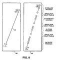
- Figure 8 shows a close-up, face-on view of nozzle configurations for a case in which printer 30 includes print head 98 having 128 nozzles and arranged near-vertical, with each nozzle closely spaced to adjacent nozzles. Such an arrangement is preferred for single color (such as black) printing.
- the nozzles are preferably arranged at a slight oblique slant so that as the print head is moved across the recording medium, it is possible to fire the nozzles in rapid succession, rather than all at once, so as to print a vertical line.
- the power and control requirements for firing nozzles in rapid succession are significantly reduced relative to those for firing all at once.
- One preferable arrangement of slant angle would correspond to a one pixel horizontal change for every 16 vertical nozzles, at 360 dpi resolution.
- printer 30 includes different modes which may be set via commands issued to printer 30 by host processor 23 (see Figure 1).
- cartridges installed in printer 30 may eject different-sized ink droplets to form images having different resolutions.
- Whether certain modes of printer 30 are available depends, in part, on the type of cartridge installed in printer 30. That is, print heads on some types of cartridges are capable of ejecting different-sized droplets, e.g., large or small ink droplets, whereas print heads on other types of cartridges are capable of ejecting droplets having a single size.
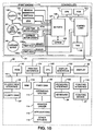
- printer 30 includes CPU 121 such as an 8-bit or a 16-bit microprocessor including programmable timer and interrupt controller, ROM 122, control logic 124, and I/O ports unit 127 connected to bus 126. Also connected to control logic 124 is RAM 129. Control logic 124 includes controllers for line feed motor 61, for print image buffer storage in RAM 129, for heat pulse generation, and for head data. Control logic 124 also provides control signals for nozzles in print heads 130a and 130b of print engine 131, carriage motor 66, line feed motor 61, and print data for print heads 130a and 130b, and receives information from print engine 131 for alignment of print heads 130a and 130b through I/O ports unit 127.
- CPU 121 such as an 8-bit or a 16-bit microprocessor including programmable timer and interrupt controller
- ROM 122 read-only memory
- control logic 124 includes controllers for line feed motor 61, for print image buffer storage in RAM 129, for heat pulse generation, and for head data. Control
- step S1403 is performed.
- printer driver 114 calculates printer parameters from data obtained by printer CPU 121 based on printer measurements related to head configuration and alignment if it is determined that the print head configuration has changed.
- the alignment system is described more fully in U.S. Patent Application No. 08/901,560, entitled “Auto-Alignment System For A Printing Device", filed on July 28, 1997 (co-pending European Application No. 98305955.1).
- step S1403 processing proceeds to step S1404, in which it is determined if printer 30 is on-line. Once it is determined that printer 30 is on-line, processing proceeds to step S1405, in which the calculated printer parameters are registered in printer EEPROM 132.
- the method for scheduling cleaning a print head in accordance with step S1405A includes receiving real time/date (time and/or date) information from an external source, storing the real time/date information in a volatile memory, storing, in a non-volatile RAM, a last cleaning time for at least one print head in the ink jet printer, and calculating an elapsed time by subtracting the stored real time/date information and the stored last cleaning time.
- real time/date time and/or date
- a device used in step S1406 for cleaning a print head during ink reservoir/cartridge change comprises a cartridge receptacle which is mounted on a carriage for releasably receiving a cartridge having a print head and at least one removable ink reservoir.
- the receptacle includes a pivoting lever which permits removal of the at least one ink reservoir.
- the lever extends over at least a portion of the at least one ink reservoir so as to prevent access to the at least one ink reservoir until such time as the lever is pivoted away from the at least one ink reservoir.
- a signal is output which prompts cleaning of the print head.
- Print head cleaning arrangements are described in greater detail in section 5.0.
- step S1409 it is determined if printer driver 114 has requested a command sequence. In the system of Figure 10, tasks of printer 30 are controlled by commands from printer driver 114 which have been generated in accordance with parameter and status information received from printer 30. When a user interface sequence is selected, step S1414 is entered and the processing shown in Figure 15 is executed.
- step S1515 When the print mode is selected in step S1506 of Figure 15, the current head configuration is displayed to the user (step S1515).
- the user may select, in step S1517, print, media type, media size, target image, custom page setting, utility or cancel operations.
- the selection of media type (step S1518), media size (step S1519), target image (step S1520) (i.e., text and color or photo-color), custom paper size (step S1521), and custom setting page (step S1522) causes information to be stored in printer driver 114 which controls the print parameters and print data for the print sequence to be performed.
- control Upon completion of the user selections by means of keyboard and pointer entry on the user interface display, control is returned to step S1409 and is directed to use print command sequence step S1410.
- step S1411 of Figure 14 Upon completion of printing one page, flow proceeds to step S1411 of Figure 14, wherein the page is output from printer 30 responsive to a paper eject command.
- Printer 30 then ejects the page to a pair of angled retractable flaps adjustably positioned by springs on a tray as described in section 4.0. While moving onto the tray during printing, the level at which a page slides onto previously-ejected pages is maintained by downward movement the flaps so that the page does not bend in the print head area. Such bending may cause distortion of an image being printed.
- the paper ejection tray has a structure which facilitates storage and setup.
- a virtual skip is then performed by printer driver 114 in step S1608 to keep track of the lines of the page being printed.
- a page finish is determined in decision step S1609, a page eject command is sent by printer driver 114 to printer control 140, which selects a page eject operation (step S1616) and starts page eject (step S1617).
- printer driver 114 is notified of the completion of the page eject and control is passed to step S1409 of Figure 14.
- a paper load command [LOAD] to load a page or other print medium and a raster skip command [SKIP] to skip to the print position of the first print head scan are sent to printer 30, and the print direction and edges for printing of print heads 130a and 130b are set for the first scan.
- a loop of commands is then sent to control printer tasks for printing the lines of the page. In the first portion of the loop for each line, the scanning parameters for the line are set as described with respect to Figure 17.
- each aspect of printer operation is controlled by printer driver 114 taking into account print head configuration and the print mode.
- the tasks to be performed by printer 30 are thereby defined in detail by printer driver 114 so that the printer architecture is substantially simplified to be less costly.
- the operating system allows for four different types of programs, each of which is executed by the operating system in accordance with its specific type.
- the types are initialization routines, tasks, interrupt handlers, and cyclic handlers.
- Initialization routines are routines scheduled by the operating system immediately after printer 30 is reset but after the operating system initializes itself.
- Tasks are ordinary programs (sometimes called "execution units") of continuous processing that are executed sequentially.
- execution units are one or more sequences of instructions handled by the operating system as units of work executed by CPU 121 in a multiple-programming or multiple-processing environment. An illusion of concurrent processing is created by the operating system by scheduling processing in individual task units.
- An interrupt handler is a (usually short) program unit that is activated by the operating system immediately upon receipt of a hardware interrupt. Cyclic handlers are similar to interrupt handlers, but rather than being activated by a hardware interrupt, cyclic handlers are activated by a timer interrupt of the operating system.
- the operating system uses semaphores as one basic means of communication between tasks and for control or synchronization between tasks. Tasks can also communicate and transfer data therebetween using messages. Messages are sent to mailboxes by one task, and a task that needs to receive the message issues a receive request to the mailbox so as to obtain the message.
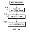
- Figures 19 and 20 illustrate a hard power-on sequence and a soft power-on sequence, respectively.
- CPU 121 is executing software regardless of the status of power button 44.
- a "hard power-on” refers to initial application of power to printer 30.
- user activation of power button 44 simply causes a soft power-on or soft power-off. This arrangement is preferred, since it allows printer 30 to monitor ongoing events (such as elapsed time) even when printer 30 is "off”.
- step S1901 upon initial application of power, step S1901 performs memory checks such as a ROM check, a RAM check, and an EEPROM check.
- step S1902 initializes software tasks, and in step S1903, CPU 121 enters an idle loop, awaiting a soft power on.
- printer tasks are designed to isolate functionality so that each task is responsible for a single cohesive aspect of printer control.
- the tasks can be divided into three conceptual groups, namely engine tasks, controller tasks, and miscellaneous tasks.
- control tasks are provided to interpret commands received from host processor 23; these commands are described in detail below in section 3.6. Test-related tasks may be provided if desired.
- Cyclic handlers are provided for communications task 204 and for user interface tasks 202, as shown and described above in connection with Figure 22.
- the 500 ms interrupt effects main heating control.
- the 1 sec. interrupt calculates environmental temperature, and then proceeds to update target temperatures based on the calculated environmental temperature.
- Control commands serve to control print operations of printer 30. The following is a description of the various control commands.
- the Raster Skip command is used to advance the vertical print position by the number of raster lines specified by a Skip parameter.
- the Mode parameter of the Select Data Compression command specifies whether the image data is compressed or un-compressed, with un-compressed being the default setting.
- the Define Print Buffer command is used to define the memory size and configuration of print buffer 139, for each of heads A and B in common.
- the Direction parameter of this command specifies whether printing will be in the forward direction (left to right) or the backward direction (right to left).
- the Select Heat Pulse Table command is used to select one heat pulse block table, from among plural tables defined by the [DEFINE_PULSE] command above, that is in common with all heads.
- Maintenance commands serve to maintain print operations of printer 30 and are described in more detail below.
- Basic Setting Commands are commands used by host processor 23 to set printer 30 and do not necessarily require a response from printer 30.
- this aspect of the present invention is an ejection tray for use with the printer described herein.
- the printer includes a housing defining a media feed portion and a media eject port, where the housing is adapted to house a print engine for printing onto recording media.
- the ejection tray includes a base slidably receivable in the printer's housing at a position laterally distanced from the media eject port.
- the base includes at least a pair of recesses extending in a sliding direction of the base.
- a pair of flaps are also included in the ejection tray. The pair of flaps each have at least one width portion corresponding to the lateral distance between the base and the eject port.
- flap 241b is also included on flap 241b.
- Spring 242b is wound around center rod 248 and connected to both flap 241b and base 240. Inherent tension in spring 242b biases flap 241b in an upward direction out of recess 264b when paper ejection tray 41 is outside of housing 31.
- flap 241b is at an initial angle relative to base 240 when no downward force is applied to flap 241b. Examples of this initial angle, labelled 249a and 249b, are shown in Figure 24. In preferred embodiments of the invention, the initial angle is less than 90°.
- flaps 241a and 241b When downward pressure is applied to flaps 241a and 241b, springs 242a and 242b are compressed. However, springs 242a and 242b prevent flaps 241a and 241b from contacting base 240 at least until a predetermined amount of pressure is applied to flaps 241a and 241b. Thus, when pressure is applied to flaps 241a and 241b, flaps 241a and 241b move angularly downward towards base 240, but do so in a controlled manner. During this motion, the angle between each of flaps 241a and 241b and base 240 decreases from the initial angle, eventually down to 0° if the pressure is sufficiently great. In this regard, the amount of pressure required to move each of flaps 241a and 241b down to 0° is based on the tension of a corresponding one of springs 242a and 242b.
- manual stop 269 can be helpful in setting up and storing paper ejection tray 41. That is, as shown in Figure 1, when paper ejection tray 41 is stored within tray receptacle 42, manual stop 269 does not fit entirely within tray receptacle 42 and therefore remains accessible to a user. By grasping manual stop 269 and pulling manual stop 269 away from printer 30, the user is able to set paper ejection tray 41 up for operation. Conversely, by pushing on manual stop 269 towards printer 30, the user can store paper ejection tray 41 within printer 30. These operations are described in greater detail below.
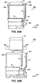
- Figures 29A to 29D show the operation of paper ejection tray 41 during use.
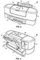
- Figure 1 shows printer 30 when not in use. In this configuration, paper ejection tray 41 is stored within receptacle 42. It is preferable to store paper ejection tray 41 when printer 30 is not in use, since storage reduces the chances that paper ejection tray 41 will be inadvertently damaged.
- a user To set up paper ejection tray 41, a user simply pulls paper ejection tray 41 out of printer 30, thereby causing paper ejection tray 41 to slide out of receptacle 42 in housing 31. This is typically done by pulling on manual stop 269; although pulling on other portions of paper ejection tray 41 will accomplish the same result. During this pulling action, flaps 241a and 241b remain relatively flat against base 240 until flaps 241a and 241b are freed from tray receptacle 42.
- flaps 241a and 241b move downward in response to an applied force depends on the tension of springs 242a and 242b biasing flaps 241a and 241b relative to base 240.
- springs 242a and 242b have a tension such that flaps 241a and 241b are biased to a height of media eject port 40 when no paper is ejected thereon.
- the position to which paper is ejected remains relatively the same for all sheets of paper.
- receptacle 42 on printer 30 includes exterior edge 272.
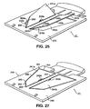
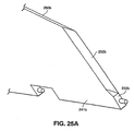
- each of flaps 241a and 241b includes a side edge (i.e., side edges 252 and 252b shown in Figures 25 and 27) which faces printer 30, which is angled away from printer 30, and which is beveled, as described above with respect to Figures 25A, 25B and 25C, such that the side edge is substantially flat and angled relative to the top edge and base.
- these side edges namely side edges 252 and 252b, are constructed in this manner so as to facilitate storage of paper ejection tray 41 within tray receptacle 42.
- this equal but opposite force includes a downward component which forces flaps 241a and 241b to move downward towards base 240.
- additional lateral pushing force is applied to ejection tray 41, side edges 252 and 252b slide against exterior edge 272, forcing flaps even further downward.
- flap 2410 operates in a manner similar to the flaps described above in the first embodiment. Specifically, as paper is ejected onto flap 2410, flap 2410 moves downwardly toward recess 2440 and eventually, when enough paper has been ejected, into recess 2440. As was the case above, downward motion of flap 2410 is controlled via a spring (not shown) which biases flap 2410 relative to recess 2440.
- this aspect of the present invention is a cartridge receptacle which is mounted on a carriage for releasably receiving a cartridge having a print head and at least one removable ink reservoir.
- the receptacle includes a pivoting lever which permits removal of the at least one ink reservoir.
- the lever extends over at least a portion of the at least one ink reservoir so as to prevent access to the at least one ink reservoir until such time as the lever is pivoted away from the at least one ink reservoir.
- a signal is output which prompts cleaning of the print head.
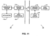
- printer 30 enters an online mode and awaits commands from host processor 23. As shown in Figure 10, host processor 23 sends commands through printer interface 104 directly to control logic 124 of printer 30. Commands from host processor 23 to read/write to EEPROM 132 of printer 30 are also directed through printer interface 104 and control logic 124.
- test pattern data stored in RAM 129 remains there until host processor 23 sends a status request [SENSOR_RESULTS] command to printer 30.
- printer 30 Upon receiving the [SENSOR_RESULTS] command, in step S3410 printer 30 transmits the test pattern data stored in RAM 129 to host processor 23.
- host processor 23 retrieves compensation equations from disk 25 and uses the equations with the received data in order to derive compensation parameters.
- host processor 23 sends a [NVRAM] control command to printer 30 which causes printer 30 to write the compensation parameters into EEPROM 132 in step S3411.
- step S3505 CPU 121 resets variables Delta T_A, which represents an elapsed time since print head A (e.g., print head 130a from Figure 10) was last cleaned. This variable, when enabled, is incremented in one second intervals and is cleared after every hard power-off. Similarly, CPU 121 also resets Delta T_B for a print head B (e.g., print head 130b from Figure 10).
- step S3607 it is determined if the RealTime reaches the maximum value of 73 hours or at the maximum value of its variable range. If it has, then flow proceeds to the automatic cleaning sequence, discussed below. Alternatively, if the value of RealTime reaches the maximum value, it may be ignored and reset. This prevents the value from overflowing in memory. On the other hand, if the real-time has not reached the maximum value, then the real-time is incremented by one second in step S3608.
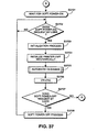
- printer 30 After performing the automatic cleaning operation, printer 30 goes online in step S3706 and awaits either print commands from host processor 23 or a soft power off entered by the user in step S3707. If neither of these events occurs, printer 30 remains in a wait state for commands from host processor 23. On the other hand, if a soft power-off request has been received, printer 30, in step S3708 performs its soft power-off process by performing a status check and updating parameters in EEPROM 132 based on the current status of printer 30.
- step S3805 if FlagRecordYet_A and FlagRecordYet_B have not been set, flow proceeds to step S3813 where FlagRealTimeActive is set in order to indicate that the real-time has been set.
- step S3803 if the real-time has been stored from a previous printing operation and it is determined to be a valid time, flow proceeds to step S3814 in which previously-downloaded new time data is compared to the real-time data. If the differences between the new time data and the real-time data are acceptable in step S3815, then the difference is ignored in step S3818 and flow proceeds.
- step S3903 FlagRealTimeReset is set so that the new time data is reset as the real-time. In this case, print head A is forcibly cleaned, because real-time has been reset in step S3817.
- step S4101 print head replacement processing begins.
- step S4102 CPU 121 awaits the termination of a head replacement mode by the user.
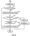
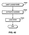
- step S4103 the replacement process is terminated. Therefore, in step S4104, CPU 121 checks to see which head has been removed; i.e., which print head has engaged and disengaged a circuit contact on its corresponding cartridge receptacle. If print head A has been removed, then in step S4105 print head A is cleaned. The cleaning is performed in the same fashion as described with respect to the flow in Figure 40. Similar processing is performed for print head B in steps S4106 and S4107.
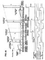
- Figure 43 is an example of a typical cleaning schedule for a print head, which is performed in accordance with the present invention as described above with respect to Figures 35 to 42.
- printer 30 maintains separate cleaning times and cleaning schedules for each of print heads 130a and 130b. The reason for this is that one print head may be replaced before the other or one may not be used in a 73 hour period. For example, when printing only text documents, the black print head will be used more than the colored print head. Therefore, the black print head may need to be cleaned more frequently than the color print head. That is, it may not be necessary to clean the color print head until immediately before a printing even if it has been more than 73 hours from last cleaning and soft power-on has occurred. In this manner, ink may be saved.
- printer 30 performs its initialization process and the last cleaning times are read from EEPROM 132. Because it is the first power-on, all flags and variables are reset. As discussed above, this reset will initiate a cleaning process upon the soft power-on. In the example shown in Figure 43, because a soft power-on is performed prior to installing a head into the printer, a cleaning will not be performed until the head is installed. Once the head is installed, an automatic cleaning is performed for each of print heads 130a and 130b. The Delta_T variable is set to 0 for all print heads and FlagRecordYet is set as discussed above in steps S4006 and S4007.
- printer 30 goes online. Recognizing that printer 30 is online, host processor 23 sends the first print job and a universal coordinated time (UCT) command, which provides the current date and time stamp. When the UCT command is received for the first time, FlagRealTimeActive is set and the new time is set as the real-time. In the present example, because the last cleaning was less than 73 hours since the print head was installed, an automatic cleaning process is not performed at T1.
- UCT universal coordinated time
- a print command provides the next new time data at T3.
- the difference between the new time data and the real-time data is calculated.
- the difference between time T3 and time T2 is greater than 73 hours, and a cleaning is pebformed. Since the internal clock of printer 30 has been active since the previous date stamp, the elapsed real-time should be the same as the new real-time downloaded at the beginning of the print job. As a result, there is no need to store the newly downloaded time.
- printer 30 Following printing of the print job, printer 30 performs a hard power-off which clears all stored times. A hard power-on follows and resets all flags and variables. The hard power-on is followed by a soft power-on which places printer 30 online. Once online, the host processor sends a print job which is prefaced with a UCT command which provides the current time and date at T4. As discussed with respect to Figure 38, since FlagRealTimeActive has not been set, the real-time that is download is stored as the new time and FlagRealTimeActive is set.
- a hard power-off occurs which clears the stored times.
- the next hard power-on resets all variables and flags.
- elapsed time variables are incremented in intervals of one second.
- a period of 73 hours elapses before the next soft power-on.
- a cleaning is performed. This cleaning is performed based on printer 30's own internal elapsed clock and not a real-time download because printer 30 has been idle for more than 73 hours without receiving a print job.
- cleaning of the print head, after 73 hours has elapsed on the internal clock may not be required and may be rescheduled for immediately before a printing operation. By postponing cleaning until immediately before printing in this manner, ink can be conserved.
- EEPROM 132 can be replaced with any kind of non-volatile memory such as a static-ram with battery backup, or flash memory, etc.
- information including the last cleaning time discussed above, can be stored in similar types of non-volatile memory devices.
- ROM 122 can be replaced with any kind of rewritable memory device, such as a flash memory, etc.
- such memory devices can receive program code downloaded to printer 30 via interface 104 of host processor 23 and host computer interface 141 of printer 30. It is also possible to utilize a memory device to memorize all information in a specific area of the memory device instead of EEPROM 132.
- communication line 106 was deccribed as bi-directional, even a unidirectional interface can be used with this invention. More specifically, while the IEEE-1284 interface was implemented in the above description, any kind of interface like SCSI, USB (Universal Serial Bus), and IEEE-1394 (high speed serial bus interface), etc. may be used in its place.
- IEEE-1284 interface was implemented in the above description, any kind of interface like SCSI, USB (Universal Serial Bus), and IEEE-1394 (high speed serial bus interface), etc. may be used in its place.
- print heads 130a and 130b are designed to be removable and replaceable into printer 30, and because different kinds of cartridges (such as cartridges having different nozzle configurations and different ink characteristics) can be loaded into print head receptacles 64a and 64b, printer 30 is pre-loaded with print head driving parameters for many different types of print heads.
- the pulse width sequence for driving each individual nozzle so as to eject an ink droplet is heavily dependent on temperature of the print head, ink characteristics (for example, whether color or black and whether dye or pigment), temperature of the surrounding environment, ink droplet size, and the like.
- ROM 122 includes pre-stored tables defining driving pulse sequences for various head/ink/resolution combinations. The pre-stored tables in ROM 122 cover various known combinations of head/ink/resolutions, as well as anticipated combinations of head/ink/resolutions.
- printer 30 includes within ROM 122 various tables of heat-up coefficients for known combinations of head/ink/resolution, as well as anticipated combinations of head/ink/resolution.
- One embodiment of the present invention addresses this desire by providing for modification of the values in pre-stored tables via commands from host processor 23, and by permitting real-time definition of print head control parameters from host processor 23.
- commands from host processor 23 it is possible through the use of commands from host processor 23 to define print head driving parameters which are suitable for controlling the functionality of newly-developed cartridges, or other cartridges for which pre-stored tables in ROM 122 are not available, ordinarily without changing ROM tables or other printer hardware.
- a printer controller that receives commands from an external processor controls a process function of a printer having a detachable cartridge based on the commands.
- the commands are capable of defining new cartridge driving parameters which are tailored to control functionality of new cartridges for which pre-stored driving parameters are not already available in the printer.
- Such parameters include, for example, timing for heat pulse sequences so as to eject ink droplets, heat-up coefficients for calculating print head temperatures needed for such heat pulse sequences, print speed, droplet size, buffer readout control, nozzle firing sequence, and the like.
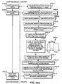
- Figure 43A is a flow diagram illustrating a first embodiment of the invention, in which a command that defines driving control parameters for a print head is comprised by a command to modify values in pre-stored tables of print head driving conditions.
- a command that defines driving control parameters for a print head is comprised by a command to modify values in pre-stored tables of print head driving conditions.
- an external host processor sends a command to modify the pre-stored look-up table such as by modification through multiplication by a control ratio.
- a print controller obtains print head driving conditions form the pre-stored look-up table and modifies the print head driving conditions so as to obtain modified print head driving parameters.
- the modified print head driving parameters are then subsequently used for print operations.
- step S43103 printer 30 receives a command for a control ratio for head temperature calculations.
- the command is received from host processor 23 (step S43104), and in the absence of receipt of such a command, printer 30 maintains a default value of 100%.
- the control ratio for head temperature calculations is applied as a multiplication factor against pre-stored values of heat-up coefficients used for calculating head temperature, as described more fully below in connection with step S43115.
- steps S43101 through S43104 are effected through use of the change pulse ratio command ([PCR]) defined above in Section 3.6.
- the [PCR] command is used to change a ratio of pulse control tables such as a ratio of heat-up coefficients used for calculating head temperature, and such as changing a ratio of pulse widths for a pulse width driving sequence for each individual nozzle of print heads 130a and 130b when ejecting an ink droplet from the nozzle.
- steps S43106 through S43115 are executed repeatedly at cyclic intervals of, for example, 50 ms so as to maintain in real time the most current values for print head driving parameters. More specifically, as described above in connection with Figure 23, steps S43106 through S43115 are executed at 50 ms cyclic intervals, for example, so as to calculate head temperature and to derive pulse width timings for a pulse width sequence applied to eject an ink droplet from a nozzle, together with other tasks also executed at 50 ms intervals.
- step S43106 reads current environmental temperature (T env ) from an unshown thermistor in printer 30.
- the current environmental temperature may be the most current value read from the thermistor, or more preferably the actual value read from the thermistor is subjected to low pass filtering so as to smooth any irregularities, discount bad readings of the thermistor, remove noise such as analog-to-digital sampling noise, and the like.
- one portion of ROM 122 includes pre-stored tables 701 for heat-up coefficients.
- the tables include plural tables 702a, 702b, etc., one table for each different combination of printer head, ink characteristics, and resolution.
- Each of the plural tables includes tabularly accessed coefficients such as the coefficients labelled 1, 2 and 3 (reference numerals 703, 704 and 705), which are accessed through look-up operation based on the number of ink drops ejected in any one particular interval, for example, 50 ms (as indicated at reference numeral 706).
- Modification in step S43112 is preferably through multiplication of the driving times obtained through look-up operation in step S43111 by the control ratio received in step S43101. For this reason, the default control ratio is 100%.
- the control ratio that is commandable through the change pulse control ratio command [PCR] is constrained to lie between 1% to 200%, thereby allowing modification of pulse times from effectively negligible pulse times up to twice the values stored in tables 710.
- step S43114 printer 30 looks up heat-up coefficients for head temperature calculations.
- heat-up coefficients are obtained based on a particular combination of print head, ink and resolution, and are looked up from one of tables 702a, etc. based on the number of dots printed per cycle, each having a duration of approximately 50 ms.
- modification of the heat-up coefficients in step S43115 is through multiplication of the coefficients obtained through look-up operation in step S43114 by the control ratio received in step S43103.
- the default control ratio is 100%.
- the control ratio that is commandable through the change pulse control ratio command [PCR] is constrained to lie between 1% to 200%, thereby allowing modification of heat-up coefficient from effectively negligible values up to twice the values stored in tables 701.
- step S43116 printer 30 controls nozzle driving based on the modified driving times obtained in step S43112, all in response to a command from host processor 23 that sends print data to printer 30, and a command for printer 30 to print such data (step S43117).
- steps S43106 through S43115 being executed at 50 ms cyclic intervals, for example, and with control over nozzle driving based on modified driving times, as set out in step S43116, being executed as commanded by host processor 23.
- control ratios for driving as well as control ratios for head temperature calculations, may be sent from host processor 23 at any time, and are responded to by printer 30 as set out in steps S43101 and S43103 described above.
- Figure 43C shows another embodiment of the present invention by which commands capable of defining print head driving parameters for a printer having a detachable print head are sent from an external device such as host processor 23 to a print controller.
- an external device such as host processor 23
- parameters received in Figure 43C control readout order for data in print buffer 139, control the nozzle firing sequence for individual nozzles in a print head, control droplet size for droplets ejected from the nozzles, and control other print head driving parameters.
- the second type of buffer control command allows host processor 23 to select any one of them for use in subsequent printout operations.
- the select buffer control table ([SELECT_CONTROL]) command defined above in Section 3.6 is used in this operation.
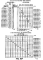
- a buffer readout control further defines the buffer data height 743 in bytes (in this example, buffer data height is 12 bytes) and print buffer height 744 (in this example, print buffer height is 12 bytes).
- a start position 745 is defined for locations in the print buffer, a portion of which is designated at 746.
- buffer readout order is being specified for 360 dpi printing.
- the nozzle slant corresponds to one printed pixel horizontally for 16 vertical nozzles. Accordingly, the first two bytes in the print buffer (corresponding to 16 bits, one for each of the first 16 nozzles in yellow ink), are read out sequentially.
- buffer readout order is affected by physical arrangement of nozzles on the print head, including gaps and slant angles, actual nozzles used for printing, print resolution and the like.
- One way to specify buffer readout order therefore involves a specification of the nozzle start position, nozzle offsets, print buffer data height, print buffer height, and byte offsets for bytes in the print buffer that correspond to nozzles used in printing.
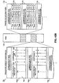
- Figure 43F shows examples of buffer readout order when using a print head comprised of 128 nozzles of black ink arranged sequentially on a print head with a slant angle, as shown at 98 in Figure 8.
- a nozzle arrangement 759 differs from the fictitious standard of a 256 nozzle head by beginning at a nozzle start position 760 of 16 bytes lower.
- Nozzle offset 761 indicate 16 sequential eight bit groups of nozzles.
- Print buffer data height 762 is set at 16 bytes, as is print buffer height 764.
- Buffer offset 765 shows how the buffer readout order is affected by the slant of the print heads, as overlayed onto a portion 746 of the print buffer.
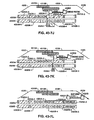
- print head 4330 moves in the forward direction without any printing until it reaches a uniform scanning speed. Since there is no printing, there is no emptying of any print data in print buffer 4320 and there is consequently no room in print buffer 4320 so as to transfer print data for a next scan from print data store 136.
- printer driver 114 determines that there is a vacant or empty area in printer buffer 4320 is through use of a signal from printer 30 that indicates that data transfer to printer 30 can not currently be accepted. Examples of such a signal include a "busy" signal or a “not-ready” signal or the like, and will hereinafter be referred to as a "busy signal”.
- the busy signal is generated by printer 30 and transmitted over host computer interface 141 to host processor 23. Specifically, since printer 30 utilizes a stepper motor for stepping its carriage across the recording medium, printer 30 at all times knows the print position of its print head 4330. Printer 30 further knows the left and right edges of the currently unprinted areas in printer buffer 4320.
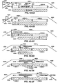
- FIGs 43-1C through 43-1E more and more print data from the current scan is printed from print buffer 4320 onto the recording medium, as signified at 4315.
- print driver 114 transmits successive blocks of print data for a next scan from area 4325 of print data store 136 to print buffer 4320.
- a second block of print data is transmitted from 4325 to 4320
- successive blocks 3 through 8 are transmitted from print data store 4325 to print buffer 4320
- a sixteenth block of print data for a next scan is transmitted from print data store 4325 to print buffer 4320.
- print head 4330 begins its ramp-down operation.
- print head 4330 it is now possible for print head 4330 to begin printing in a reverse direction, utilizing the print data for the next scan that has now been stored in print buffer 4320, during which print data for a further successive scan will be transmitted by printer driver 114 from print data store 136 to print buffer 139.
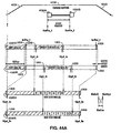
- print driver 114 does not need to rely exclusively on busy/ready signal generation from printer 30, in order to determine whether there are empty spaces in the print buffer into which to store print data for a next scan. specifically, because it was the print driver that previously transmitted data for the current scan for storage into particular print buffer locations, the print driver can determine without any feedback from the printer exactly which locations in the print buffer should be empty and ready to receive print data for a next scan.
- Printer 30 might generate a busy signal during print driver transmission of print data, but the busy signal would ordinarily be generated for reasons unrelated to the empty/full status of print buffer locations (e.g., the printer might not be ready to receive new data because it is occupied with other tasks such as head cleaning).
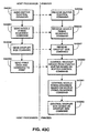
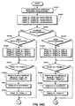
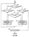
- printer driver 114 tests whether EdgeL_An for the next scan is less than EdgeR_An for the next scan but EdgeL_Bn for the next scan is not less than EdgeR_Bn for the next scan. If these conditions are met, there is overlapped data only in buffer 4320A. Consequently, one predetermined small block of print data for print buffer 4320A is sent from the left block to the right block addresses of the block to print buffer 4320A (step S4431; see Figure 44G). Step S4427 is then reentered for transfer of the print data of the next small block transfer.
- step S4430 decides whether EdgeL_Bn is greater than or equal to EdgeL_An + the gap between print heads 4330A and 4330B. If so, data for buffer 4320A precedes that for buffer 4320B. Consequently, a small predetermined print data block for print buffer 4320A is sent to print buffer 4320A from print data store 136 of host processor 23 (step S4431). On the other hand, a "NO" decision in step S4430 indicates that data for buffer 4320B precedes that for buffer 4320A. Consequently, a small predetermined print data block for print buffer 4320B is sent to print buffer 4320B from print data store 136 of host processor 23 (step S4434) and control is returned to step S4427.
- Print buffer 4320B is then processed for right edge print data transfer in steps S4452 through S4456.
- a block select command [BLOCK] and a data command [DATA] are sent to printer 30.
- the block select command is sent with a block left edge address of EdgeR_B+1 (i.e., current scan right edge +1) and a block right edge address of EdgeR_Bn (i.e., next scan right edge).
- the right edge of the next scan, EdgeR_Bn is then reset to EdgeR_B (step S4456).
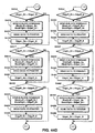
- Print buffer 4320B is then processed for left edge print data transfer in steps S4462 through S4466.
- a block select command [BLOCK] and a data command [DATA] are sent to printer 30.
- the block select command is sent with a block left edge address of EdgeL_Bn (i.e., next scan left edge) and a block right edge address of EdgeL_B-1 (i.e., current scan left edge-1).
- the left edge of the next scan, EdgeL_Bn is then reset to EdgeL_B (step S4466).
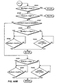
- step S4487 a block command is sent to print buffer 4320B with a left block address of EdgeL_Bn and a right block address of EdgeL_B-1 (step S4491), print data so addressed is sent to print buffer 4320B (S4492) and the left edge, EdgeL_Bn, of the next scan print data is set to EdgeL_B (step S4493).
- a block command is sent to print buffer 4320B with a left block address of EdgeL_Bn and a right block address of EdgeR_Bn (step S4518), print data so addressed is sent to print buffer 4320B (S4519) and the left edge of the next scan print data, EdgeR_Bn, is set to EdgeL_Bn (S4520).
- step S4517 If "NO” in step S4517, a block command is sent to print buffer 4320B with a left block address of EdgeR_B+1 and a right block address of EdgeR_Bn (step S4521), print data so addressed is sent to print buffer 4320B (S4522) and the right edge of the next scan print data, EdgeR_Bn, is set to EdgeR_B (step S4523).
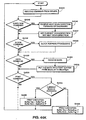
- step S4544 If the block which is specified by the printer driver becomes vacant entirely, then put the data block into the printer buffer and release any busy signal so as to signify to the printer driver that the printer is ready to accept data; and (4) If the current scan is forward direction, then the printer prints shifted buffer. If the current scan is backward direction, then printer prints the non-shifted buffer.
- decision steps S4545, S4548, S4550, S4553 and others are sequentially performed when a command from printer driver 114 is received in step S4544.
- step S4541 When the current scan direction in step S4540 is the forward direction, the left and right edges of the designated print buffer are set to provide shifting of the print data of the next scan. Accordingly, in step S4541 the left edge EdgeL_X is set to EdgeL_X plus the shift area length and the right edge EdgeR_X is set to EdgeR_X plus the shift area length.
- the current scan direction is the backward direction, no adjustment is needed since there are no predefined shift areas at the bottom ends of the print buffers.
- the next scan direction is checked in step S4542.
- step S4527 is entered wherein it is determined if the current scan direction is the forward direction. If there is a "YES” decision in step S4527, it is determined whether the BlockRight address is less than or equal to EdgeR_X (S4528).
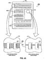
- printer 30 has multiple print heads, and because of software architecture in which commands affecting resolution are sent to each print head independently, printer 30 can print and can be controlled to print with differing resolutions for each print head so as to increase overall print efficiency in situations where print data for one page includes print information for which a higher resolution is desired mixed with print data for which a lower resolution is adequate.
- area 402a is a text area for which low resolution is adequate
- printing of area 402 is effected by print head 130b.
- This arrangement is shown at 405 in which one band 406 from print head 130b is depicted in cross-hatched emphasis.
- printer 30 is commanded to put print head 130b into a large droplet ejection mode, and print data readout order from print buffer 139 is selected in accordance with the head configuration of print head 130b and in accordance with the selected resolution.
- step S4501 a user of host processor 23 issues a command from an application to print print data, thereby actuating printer driver 114.
- Printer driver 114 actually performs many more functions than indicated in the remainder of Figure 45, but only those functions having some bearing on setting of print resolution independently are described.
- printer driver 114 determines whether print resolution should be designated automatically by printer driver 114, or whether the print resolution should be designated manually by the user.
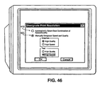
- a user interface is displayed to the user, such as the representative user interface shown in Figure 46. As seen there, section 410, when selected by the user, provides for automatic designation of print resolution. On the other hand, when 411 is selected, the user manually designates print resolution. Separate resolutions may be specified for non-text graphics as well as for text, with the user being able to designate manually either high speed (i.e., low resolution) or high quality (i.e., high resolution) for each of text and non-text regions.
- step S4506 the printer driver determines whether dual resolutions have been specified, either manually or automatically. If no dual resolutions have been specified, then flow branches to step S4507 to proceed with printing in a uniform resolution for both heads. On the other hand, if dual resolutions have been specified, then flow advances to step S4509 so as to control print resolution of each print head independently and to effect printout thereby.
- step S4509 defines buffer control tables, one of which is selectable for each head and by which each print head can determine readout order for readout of print data from its respective print buffer. Actual selection of which buffer control table to use is not effectuated until later in the procedure, but step S4509 merely defines suitable buffer control tables for each resolution and for each direction of printout.
- the define buffer control table command [DEFINE_CONTROL] described above in section 3.6 is used.
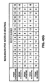
- step S4510 defines suitable heat pulse tables by which the firing sequence for each nozzle in print heads 130a and 130b is controlled.
- the actual heat pulse tables used by print heads 130a and 130b are not selected at this point, but rather suitable tables are defined for later selection.
- the define heat pulse table command [DEFINE_PULSE] described above in section 3.6 is used.
- Step S4516 selects offsets for readout order of print buffer 139 in accordance with the selected low resolution. Specifically, step S4516 selects one of the buffer control tables set above in step S4509. Preferably, the select buffer control table command [SELECT_CONTROL] defined above in section 3.6 is used.
- step S4522 sets small drop sizes
- step S4525 sets a low print speed corresponding to high resolution
- step S4526 selects a high resolution nozzle firing sequence
- step S4527 selects readout order from print buffer 139 by selecting one of the pre-defined buffer control offset tables
- step S4529 transmits high resolution image data band by band to printer 30, and step S4530 initiates printout of a fully-transmitted band.
- the resolution with which a print head prints may be determined manually by user input, or automatically based, for example, on content of print data, type of recording medium, or, in the case of a multiple print head system, a relative head configuration of print heads 130a and 130b.
- area 420b is a text area for which low resolution is adequate
- printing of area 420b is performed in a low resolution/high speed mode, as shown at 425.
- one low resolution band 426 is printed by print heads 130a and 130b and depicted in cross-hatched emphasis.
- printer 30 is commanded to put print heads 130a and 130b into a large droplet ejection mode, and print data read out from print buffer 139 is selected in accordance with the selected resolution.
- step S4601 a user of host processor 23 issues a command from an application to print print data, thereby actuating printer driver 114.
- Printer driver 114 actually performs many more functions than indicated in the remainder of Figure 46, but only those functions having some bearing on setting of print resolution are described.
- printer driver 114 determines whether print resolution should be designated automatically by printer driver 114, or whether the print resolution should be designated manually by the user.
- a user interface is displayed to the user, such as the representative user interface shown in Figure 46. As seen there, section 410, when selected by the user, provides for automatic designation of print resolution.
- the user manually designates print resolution. Separate resolutions may be specified for non-text graphics as well as for text, with the user being able to designate manually either high speed (i.e., low resolution) or high quality (i.e., high resolution) for each of text and non-text regions.
- step S4610 defines suitable heat pulse tables by which the firing sequence for each nozzle in print heads 130a and 130b is controlled.
- the actual heat pulse tables used by print heads 130a and 130b are not selected at this point, but rather suitable tables are defined for later selection.
- the define heat pulse table command [DEFINE_PULSE] described above in section 3.6 is used.
- steps S4611 through S4630 which (with the exception of steps S4620 and S4621) the resolution of a current print band is determined, print control conditions such as ink ejection drop size and buffer readout order are set, print data is sent, and printout of the transmitted print data is commanded.
- step S4611 determines whether printout for a particular band or a portion of a band is a high resolution printout or a low resolution printout. If the band or portion of the band is a low resolution printout, flow advances to step S4612 which sets appropriate ink ejection droplet sizes for each of heads 130a and 130b. Using the example from Figure 44, the droplet size for heads 130a and 130b is set to large. Preferably, the droplet size command [DROP] defined above in section 3.6 is used.
- Step S4614 printer driver 114 selects the high print speed, corresponding to low resolution printout.
- the select speed command [SPEED] defined above in section 3.6 is used.
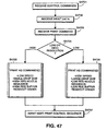
- FIG 47 is a flow diagram illustrating the process steps performed by printer 30 for independent print resolution setting.
- printer 30 receives control commands so as to prepare printer 30 for high or low print resolution for each print head.
- control commands include commands to set the speed of printing, the size of the ejected nozzle, the nozzle firing sequence, and the print buffer readout order.
- step S4702 print data is received from printer driver 114, followed in step S4703 by a print command. Thereafter, in step S4704, depending on whether a high or a low print resolution has been commanded, the print data received in step S4702 is printed as commanded in step S4701.
- step S4705 for a high print resolution, print data is printed at a low speed, with small droplet size, with a high resolution nozzle pulse sequence table, and with a high resolution buffer control readout order.
- step S4706 for a low resolution printout, printout is effected at a high speed, with a large droplet size, with a low resolution nozzle pulse sequence table, and with a low resolution buffer offset readout sequence. In either event, flow proceeds to step S4707 to await the next print command sequence.
- a single print head may be controlled to print print data on a single print band in a scanning direction using both sets of printing characteristics set forth in step S4705 and step S4706.
- recording media type plays a significant role in determining whether dye-based, or other high-penetration black inks, or low-penetration black inks such as pigment-based inks are more appropriate for a particular print job.
- flow begins at step S4801, wherein a paper type is determined.
- a paper type is determined.
- the preferred embodiment contemplates the use of either plain paper or specially-coated paper.
- the specially-coated paper is "high resolution" paper HR-101, as described in section 1.0.
- step S4802 it is determined that a high-penetration ink should be used for printing black pixel data. This determination is based on an assumption that high-penetration black ink is always more suitable for printing black pixel data upon a specially-coated recording medium, regardless of image type.
- step S4801 If, in step S4801, the paper type is determined to be plain, flow proceeds to step S4803, in which it is determined whether a black target pixel exists within a color region of the image to be printed. If so, flow proceeds to step S4802, as described above. If not, flow proceeds to step S4804, wherein it is determined to print the target pixel using low-penetration black ink.
- step S4803 is made by examining image pixels surrounding the target pixel.
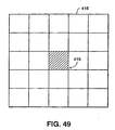
- Figure 49 is a diagram for describing this particular embodiment.
- Figure 49 shows black target pixel 415 within 5 x 5 grid of image data 416.
- Each subdivision of grid 416 represents a single image pixel.
- each image pixel is represented by three 8-bit values, each 8-bit value representing red, green, and blue components of the image pixel.
- the red, green, and blue components of each pixel in grid 416 are compared using the following equations: ⁇ R - B ⁇ ⁇ ⁇ ; ⁇ B - G ⁇ ⁇ ⁇ ; and ⁇ G - R ⁇ ⁇ , wherein ⁇ , ⁇ , and ⁇ are relatively small values.
- paper type can be detected by a paper sensor located within printer 30, or input through a user interface displayed on display screen 22, or input via a button located on printer 30.
- printer driver 114 contains computer-executable steps to execute the flow of Figure 48. Of course, these steps could be wholly contained within ROM 122 of printer 30 or could be stored jointly within computer-readable memories of host computer 23 and printer 30.
- PCBk may be utilized to print black pixels upon a recording medium.
- pigment-based black inks and dye-based black inks have also been used to print such pixels.
- Printer 30 provides additional functionality by providing selectable printing of black pixels using either pigment-based black ink or a combination of cyan, magenta, yellow, and black dye-based inks.
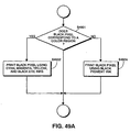
- FIG. 49A is a flow diagram for specifically describing the foregoing features.
- step S4901 it is determined whether a black target pixel corresponds to a color region. Preferably, this determination is based upon multi-level data representing a region adjacent to the black target pixel. Such a method is described in detail above with respect to Figure 49, and is therefore omitted at this point.
- PCBk has been proposed as a buffer between such a color region and a region of low-penetration black ink.
- a buffer is unsatisfactory because the different optical densities of PCBk region 422 and low-penetration black ink region 424 cause an abrupt visual discontinuity.
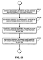
- Figure 51 is a flow diagram describing a method for printing a boundary region.
- the method includes detecting a boundary between a black region of an image and a differently-colored region of the image, instructing a printer to print a first region of black pixels within the black region and adjacent to the boundary using process black, instructing the printer to print a second region of black pixels within the black region and adjacent to the first region using high-penetration black ink, and instructing the printer to print a third region of black pixels within the black region and adjacent to the second region using low-penetration black ink.
- step S5101 a boundary between a black region of an image and a differently-colored region of the image is detected.
- step S5101 results in detection of boundary 429 between differently-colored region 430 and black region 432.
- boundary detection is preferably based on multi-level image data so as to detect black/differently-colored boundaries more accurately than systems which perform boundary detection using binarized image data.
- step S5102 in which a printer is instructed to print a first region of black pixels using PCBk.
- first region 431 is within black region 432 and adjacent to boundary 429.
- step S5104 the printer is instructed, in step S5104, to print a third region of black pixels using a low-penetration black ink.
- third region 436 is adjacent to second region 434 and within black region 432.
- Printer driver 114 may contain computer-executable steps to execute the flow of Figure 51. These steps may also be contained within ROM 122 of printer 30 or may be stored jointly within computer-readable memories of host processor 23 and printer 30.
- step S5201 a black target pixel is identified within original image data.
- step S5202 it is determined whether a first region adjacent to the target pixel includes a differently-colored region. If so, flow proceeds to step S5204, wherein printer 30 is instructed to print the target pixel using PCBk. If not, flow proceeds to step S5205.
- Figure 53A illustrates detection of a first differently-colored region according to a preferred embodiment of step S5202.
- Figure 53A shows a region of differently-colored multi-level image data 450 and a region of black multi-level image data 451.
- the target pixel identified in step S5201 is represented by pixel data location 452.
- 5 x 5 region 454 is the first region analyzed in step S5202.
- Figure 53C is a representation of printed pixels corresponding to the image data of Figure 53A.
- printed pixel 456, representing pixel location 452 is printed using PCBk.
- printed pixel 457, representing pixel location 459 is also printed using PCBk.
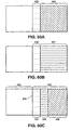
- a boundary region such as that shown in Figure 50C is obtained. Specifically, optical density changes gradually across the boundary region, bleeding between the black region and the differently-colored region is reduced, and the black region is printed using low-penetration black ink.
- sizes of the first region and of the second region may be adjusted based on a number of PCBk pixels desired and on a number of high-penetration black ink pixels desired in a boundary region between a black region and a differently-colored region.
- printer driver 114 may contain computer-executable steps to execute the flow of Figure 52. These steps may also be contained within ROM 122 of printer 30 or may be stored jointly within computer-readable memories of host processor 23 and printer 30.
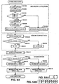
- Figure 54 is a flow diagram which depicts processing according to another embodiment. As shown in Figure 54, upon input of pixel data such as 5 x 5 pixel region 416, it is determined, in steps S5402 to S5407, whether a target pixel in the input pixel data is within a color region. This process is the same as that described above with respect to Figure 49. Accordingly, a detailed description thereof is omitted here for the sake of brevity.
- Steps S5409 to S5412 set forth color correction, i.e., black correction. Specifically, in step S5409, color correction is performed on the target pixel so as to change the pixel from RGB data into CMYK data.
- step S5410 determines if the target pixel is within a color region. If the pixel is not within a color region, processing proceeds to step S5411. In a case that the target pixel is not within a color region, pigment ink (i.e., K1 ink) is set to form the pixel.
- K1 ink i.e., K1 ink
- black is formed from process black, i.e., cyan, magenta, and yellow ink and dye-based (i.e., K2) black ink.
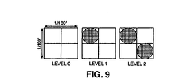
- step S5414 determines whether the target pixel is within a color region. In a case that the target pixel is within a color region, processing proceeds to step S5418, in which the target pixel is binarized with a 2 x 2 index, and to step S5419 in which the pixel is printed in 720 x 720 resolution with dye-based black pigment ink (see Figure 54A). On the other hand, in a case that step S5414 determines that the target pixel is not within a color region, processing proceeds to step S5415, in which the pixel is binarized with a 1 x 1 index, and to steps S5417 in which the pixel is printed in 360 x 360 dpi with pigment-based black ink (see Figure 54B). Thereafter, processing ends.
Landscapes
- Physics & Mathematics (AREA)
- Engineering & Computer Science (AREA)
- Mathematical Physics (AREA)
- General Engineering & Computer Science (AREA)
- General Physics & Mathematics (AREA)
- Theoretical Computer Science (AREA)
- Record Information Processing For Printing (AREA)
- Dot-Matrix Printers And Others (AREA)
- Accessory Devices And Overall Control Thereof (AREA)
- Ink Jet (AREA)
Claims (25)
- Procédé de commande d'un tampon d'impression (4320) dans une imprimante série (30) ayant au moins une tête d'impression qui est agencée de façon à imprimer une image sur un support d'enregistrement, conformément à des données d'impression arrivant en entrée depuis un dispositif hôte (23) par un balayage bidirectionnel de la tête d'impression au-dessus du support d'impression, le procédé comprenant la répétition des étapes qui consistent :à stocker dans le tampon d'impression les données d'impression pour un balayage ;à faire exécuter un balayage à la tête d'impression pendant qu'elle imprime conformément aux données d'impression stockées dans le tampon d'impression pour ce balayage ;caractérisé en ce quependant un balayage de la tête d'impression pendant une impression conforme aux données d'impression stockées dans le tampon d'impression pour le balayage en cours, certaines des données d'impression pour le balayage suivant sont stockées dans le tampon d'impression, par écrasement des données d'impression pour le balayage en cours qui ont déjà été imprimées.
- Procédé selon la revendication 1, dans lequel, si les données d'impression stockées dans le tampon d'impression pour le balayage en cours correspondent à une impression sur une largeur inférieure à la largeur maximale d'impression permise dans le tampon d'impression, en sorte qu'il y a de l'espace vide dans le tampon d'impression correspondant à des parties du balayage en cours dans lesquelles aucune impression n'est nécessaire, l'étape de stockage des données d'impression comprend le stockage, pendant une période du balayage en cours après que la tête d'impression a commencé à se déplacer et avant que la tête d'impression a commencé à imprimer, de certaines des données d'impression pour le balayage suivant dans ledit espace vide pourvu qu'il y ait des données d'impression pour le balayage suivant correspondant audit espace vide.
- Procédé selon la revendication 2, dans lequel l'étape de stockage de données d'impression comprend le stockage, pendant une période avant que la tête d'impression ait commencé à imprimer des données d'impression stockées pour le balayage en cours, de certaines des données d'impression pour le balayage suivant dans une zone du tampon d'impression s'étendant depuis une première extrémité du tampon d'impression jusqu'à l'adresse de début des données d'impression stockées pour le balayage en cours, et dans une autre zone du tampon d'impression s'étendant depuis l'adresse de fin des données d'impression stockées pour le balayage en cours jusqu'à l'autre extrémité du tampon d'impression.
- Procédé selon la revendication 1 ou la revendication 2 pour commander un tampon d'impression dont la taille est supérieure à la taille nécessaire au stockage de données d'impression pour un balayage unique de la tête d'impression,
procédé dans lequel l'étape de stockage des données d'impression comprend le stockage, pendant une période pour l'accélération de la tête d'impression avant le commencement de l'impression des données d'impression pour le balayage en cours, de certaines des données d'impression pour le balayage suivant dans la partie du tampon d'impression qui ne stocke pas de données d'impression pour le balayage en cours. - Procédé selon la revendication 4 dans lequel, pour chaque balayage de la tête d'impression, une partie du tampon d'impression, qui est assez grande pour stocker des données d'impression pour un balayage unique de la tête d'impression, stocke les données d'impression pour le balayage en cours et, en référence à la direction correspondant à la direction de balayage de la tête d'impression pendant le balayage en cours, la partie du tampon d'impression dans laquelle des données d'impression pour le balayage suivant sont stockées pendant la période d'accélération précède le commencement de ladite partie pour le balayage en cours.
- Procédé selon l'une quelconque des revendications précédentes, comprenant l'étape qui consiste à délivrer en sortie un signal d'occupation au dispositif hôte s'il est déterminé qu'il n'y a pas d'espace dans le tampon d'impression pour l'écriture de nouvelles données d'impression sans écrasement de données d'impression qui n'ont pas encore été imprimées.
- Procédé selon l'une quelconque des revendications précédentes, dans lequel les données d'impression pour le balayage suivant sont stockées en plusieurs blocs de données, correspondant chacun à une zone respective devant être imprimée, les blocs qui sont stockés pendant le balayage en cours de façon à écraser les données d'impression pour le balayage en cours étant stockés dans l'ordre des positions des zones respectives dans la direction du mouvement de la tête d'impression pendant le balayage en cours et dans l'ordre inverse par rapport à l'ordre dans lequel elles seront imprimées lors du balayage suivant.
- Procédé selon l'une quelconque des revendications précédentes, dans lequel, dans l'étape de stockage, les données d'impression pour le balayage suivant sont stockées conformément à une adresse du tampon d'impression reçue du dispositif hôte.
- Procédé selon la revendication 8, dans lequel les données d'impression pour le balayage suivant sont stockées en plusieurs blocs de données, chaque bloc étant stocké en un emplacement dans le tampon d'impression spécifié par le dispositif hôte, et lorsqu'un code est reçu du dispositif hôte, spécifiant l'emplacement pour le stockage d'un bloc de données d'impression, soit le bloc suivant de données d'impression reçues du dispositif hôte est stocké à l'emplacement spécifié, soit un signal d'occupation est envoyé au dispositif hôte, suivant que l'emplacement spécifié recouvre ou non toutes données d'impression non imprimées dans le tampon d'impression.
- Procédé selon l'une quelconque des revendications précédentes, comprenant en outre l'étape consistant à extraire les données d'impression stockées dans le tampon d'impression pour le balayage en cours, conformément à un ordre reçu du dispositif hôte.
- Procédé selon l'une quelconque des revendications précédentes, dans lequel les bords de gauche et de droite de la zone devant être imprimée sur le support d'enregistrement sont établis conformément à un code reçu du dispositif hôte.
- Procédé selon l'une quelconque des revendications précédentes, qui comprend le traitement des données d'impression arrivant en entrée du dispositif hôte comme étant un format de colonnes.
- Procédé de commande de tampons d'impression (4320A, 4320B) dans une imprimante série (30) ayant plusieurs têtes d'impression (4330A, 4330B), agencées chacune pour imprimer sur un support d'enregistrement, par un balayage bidirectionnel de la tête au-dessus du support d'enregistrement, conformément à des données d'impression arrivant en entrée d'un dispositif hôte (23) et stockées dans l'un, respectif, de plusieurs tampons d'impression, le procédé comprenant la commande de chaque tampon d'impression respectif par un procédé selon l'une quelconque des revendications précédentes.
- Imprimante série comportant un tampon d'impression (4320) et agencée pour utiliser au moins une tête d'impression afin d'imprimer une image sur un support d'enregistrement, conformément à des données d'impression arrivant en entrée d'un dispositif hôte (23), par un balayage bidirectionnel de la tête d'impression au-dessus du support d'enregistrement, l'imprimante étant agencée pour commander le tampon d'impression par un procédé selon l'une quelconque des revendications 1 à 12.
- Imprimante série comportant plusieurs tampons d'impression et agencée pour utiliser plusieurs têtes d'impression afin d'imprimer une image sur un support d'enregistrement, par un balayage bidirectionnel des têtes au-dessus du support d'enregistrement, conformément à des données d'impression arrivant en entrée d'un dispositif hôte (23) et stockées dans certains, respectifs, des tampons d'impression, l'imprimante étant agencée pour commander chacun des tampons d'impression par un procédé selon l'une quelconque des revendications 1 à 12.
- Procédé pour la mise en oeuvre d'un ordinateur en tant que dispositif hôte pour une imprimante selon la revendication 14 ou la revendication 15, le procédé comprenant l'envoi de données d'impression à l'imprimante pour des balayages successifs de la tête d'impression,
caractérisé en ce que
l'ordinateur s'assure des emplacements dans le tampon d'impression auxquels des données d'impression pour chaque balayage sont stockées, et
pendant un balayage de la tête d'impression en même temps qu'elle imprime conformément aux données d'impression stockées dans le tampon d'impression pour le balayage en cours, l'ordinateur envoie à l'imprimante des données d'impression pour le balayage suivant, devant être stockées en des emplacements dans le tampon d'impression contenant des données d'impression pour le balayage en cours qui ont déjà été imprimées. - Procédé selon la revendication 16, dans lequel l'ordinateur envoie les données d'impression pour le balayage suivant en plusieurs blocs de données correspondant chacun à une zone respective devant être imprimée, et les blocs qui doivent être stockés en des emplacements dans le tampon d'impression contenant des données d'impression pour le balayage en cours sont envoyés dans l'ordre des positions des zones respectives dans la direction du mouvement de la tête d'impression pendant le balayage en cours et dans l'ordre inverse par rapport à l'ordre dans lequel elles seront imprimées pendant la balayage suivant.
- Procédé selon la revendication 16 ou la revendication 17, dans lequel l'ordinateur spécifie à l'imprimante l'emplacement dans le tampon d'impression dans lequel les données d'impression envoyées par l'ordinateur doivent être stockées.
- Procédé selon la revendication 18, dans lequel l'ordinateur spécifie que les emplacements dans le tampon d'impression, dans lesquels des données d'impression pour le balayage suivant doivent être stockées, ne recouvrent que partiellement les emplacements dans le tampon d'impression auxquels des données d'impression pour le balayage en cours sont stockées, et l'ordinateur envoie des données d'impression pour le balayage suivant, devant être stockées dans les emplacements sans recouvrement du tampon d'impression avant d'envoyer des données d'impression pour le balayage suivant, devant être stockées dans les emplacements à recouvrement.
- Procédé selon l'une quelconque des revendications 16 à 19, dans lequel, si l'ordinateur s'assure que les données d'impression pour le balayage en cours occupent moins que l'étendue totale du tampon d'impression disponible pour le balayage en cours, de façon qu'une partie de l'étendue du tampon d'impression disponible pour le balayage en cours soit vide de données d'impression pour le balayage en cours, il envoie des données d'impression pour le balayage suivant de façon qu'elles soient stockées dans la partie vide de ladite étendue avant que la tête d'impression commence à imprimer conformément aux données d'impression pour le balayage en cours pourvu qu'il y ait des données d'impression pour le balayage suivant correspondant à ladite partie vide.
- Procédé selon l'une quelconque des revendications 16 à 20, qui comprend l'étape consistant à stocker les données d'impression pour la ligne suivante dans une zone de stockage (136, 4325) de l'ordinateur avant le commencement de l'impression des données d'impression pour le balayage en cours, et l'étape d'envoi de données d'impression pour le balayage suivant, de l'ordinateur à l'imprimante, comprend l'envoi de données d'impression stockées dans la zone de stockage.
- Procédé selon l'une quelconque des revendications 16 à 21, dans lequel les données d'impression sont envoyées à l'imprimante en un format de colonnes.
- Programme d'attaque d'imprimante pour commander un ordinateur afin qu'il fonctionne conformément au procédé selon l'une quelconque des revendications 16 à 22.
- Support de données portant des codes de programme définissant un programme d'attaque d'imprimante selon la revendication 23.
- Signal portant des codes de programme définissant un programme d'attaque d'imprimante selon la revendication 23.
Applications Claiming Priority (2)
| Application Number | Priority Date | Filing Date | Title |
|---|---|---|---|
| US972140 | 1997-11-17 | ||
| US08/972,140 US6134020A (en) | 1997-11-17 | 1997-11-17 | Serial printer with addressable print buffer |
Publications (3)
| Publication Number | Publication Date |
|---|---|
| EP0917095A2 EP0917095A2 (fr) | 1999-05-19 |
| EP0917095A3 EP0917095A3 (fr) | 2000-01-12 |
| EP0917095B1 true EP0917095B1 (fr) | 2006-02-08 |
Family
ID=25519232
Family Applications (1)
| Application Number | Title | Priority Date | Filing Date |
|---|---|---|---|
| EP98309284A Expired - Lifetime EP0917095B1 (fr) | 1997-11-17 | 1998-11-13 | Imprimante série à tampon d'impression adressable |
Country Status (4)
| Country | Link |
|---|---|
| US (1) | US6134020A (fr) |
| EP (1) | EP0917095B1 (fr) |
| JP (1) | JP3715806B2 (fr) |
| DE (1) | DE69833418T2 (fr) |
Families Citing this family (26)
| Publication number | Priority date | Publication date | Assignee | Title |
|---|---|---|---|---|
| US7084992B1 (en) * | 1997-12-23 | 2006-08-01 | Canon Research Center-France S.A. | Method and device for determining a printer pilot configuration for a printing processing |
| JPH11208029A (ja) * | 1998-01-21 | 1999-08-03 | Seiko Epson Corp | 印刷装置および印刷方法並びに記録媒体 |
| JPH11334068A (ja) * | 1998-05-26 | 1999-12-07 | Brother Ind Ltd | インク噴射装置 |
| US7437483B1 (en) * | 1999-03-24 | 2008-10-14 | Microsoft Corporation | System and method for transferring a compressed data file to a peripheral device |
| US6631976B2 (en) | 1999-04-14 | 2003-10-14 | Canon Kabushiki Kaisha | Control of ink jet nozzle prefiring |
| TW512543B (en) * | 1999-06-28 | 2002-12-01 | Semiconductor Energy Lab | Method of manufacturing an electro-optical device |
| TW468283B (en) | 1999-10-12 | 2001-12-11 | Semiconductor Energy Lab | EL display device and a method of manufacturing the same |
| TW471011B (en) * | 1999-10-13 | 2002-01-01 | Semiconductor Energy Lab | Thin film forming apparatus |
| EP1128323A3 (fr) * | 1999-12-27 | 2002-05-29 | Seiko Epson Corporation | Imprimante, méthode d'impression, et support d'enregistrement de données |
| TW495808B (en) * | 2000-02-04 | 2002-07-21 | Semiconductor Energy Lab | Thin film formation apparatus and method of manufacturing self-light-emitting device using thin film formation apparatus |
| US20020080393A1 (en) * | 2000-06-13 | 2002-06-27 | Leonard Ronald A. | Parallel printer intercept |
| ATE520534T1 (de) | 2000-12-19 | 2011-09-15 | Canon Kk | Druckvorrichtung und -verfahren |
| US6712445B2 (en) * | 2001-10-19 | 2004-03-30 | Seiko Epson Corporation | Liquid jetting apparatus |
| JP2003305837A (ja) | 2002-04-15 | 2003-10-28 | Canon Inc | 記録装置、情報処理装置及びそれらの制御方法、プログラム |
| JP2003305902A (ja) | 2002-04-15 | 2003-10-28 | Canon Inc | 記録装置、情報処理装置及びそれらの制御方法、プログラム |
| JP2004130299A (ja) * | 2002-08-02 | 2004-04-30 | Seiko Epson Corp | 液滴吐出装置、電気光学装置の製造方法、電気光学装置および電子機器 |
| JP4174264B2 (ja) * | 2002-08-12 | 2008-10-29 | キヤノン株式会社 | 記録装置及びその制御方法 |
| US8699054B2 (en) * | 2002-11-22 | 2014-04-15 | Codonics, Inc. | Media selection methods in a multi-media printer utilizing print client indicators |
| JP2004358799A (ja) * | 2003-06-04 | 2004-12-24 | Canon Inc | キャリッジ駆動制御方法 |
| JP2005022271A (ja) * | 2003-07-03 | 2005-01-27 | Canon Finetech Inc | 記録方法及び記録装置 |
| JP2006031482A (ja) * | 2004-07-16 | 2006-02-02 | Toshiba Corp | プロファイル管理方法及び管理システム |
| US20060017795A1 (en) * | 2004-07-26 | 2006-01-26 | Seiko Epson Corporation | Image forming apparatus, image forming method and data control device |
| JP4773779B2 (ja) * | 2005-09-06 | 2011-09-14 | キヤノン株式会社 | 画像形成システム、画像形成システムの制御方法、及び画像形成装置 |
| JP2007172087A (ja) * | 2005-12-19 | 2007-07-05 | Brother Ind Ltd | 仮想オブジェクトを登録するためのプログラム、該プログラムを記憶する記憶媒体、仮想オブジェクト登録方法、及び情報処理装置 |
| US9134931B2 (en) | 2013-04-30 | 2015-09-15 | Hewlett-Packard Development Company, L.P. | Printing content over a network |
| EP3911519B1 (fr) * | 2019-01-16 | 2025-03-26 | Canon Production Printing Holding B.V. | Procédé de profilage d'un médium d'impression destiné à être utilisé dans un système d'impression |
Family Cites Families (21)
| Publication number | Priority date | Publication date | Assignee | Title |
|---|---|---|---|---|
| US4692778A (en) * | 1985-03-28 | 1987-09-08 | Canon Kabushiki Kaisha | Image formation apparatus with a recording unit and paper feed cover and a sealing member |
| JP2675851B2 (ja) * | 1989-01-28 | 1997-11-12 | キヤノン株式会社 | インクジェット記録方法及び該方法に用いる装置 |
| DE69022112T2 (de) * | 1989-05-18 | 1996-02-15 | Canon Kk | Tintenstrahlaufzeichnungsgerät. |
| US5266974A (en) * | 1989-05-18 | 1993-11-30 | Canon Kabushiki Kaisha | Ink jet recording apparatus including means for controlling speed of wiper member |
| JP2859296B2 (ja) * | 1989-06-01 | 1999-02-17 | キヤノン株式会社 | 画像再生方法及びその装置 |
| JP2768788B2 (ja) * | 1990-02-26 | 1998-06-25 | キヤノン株式会社 | 記録装置 |
| KR940000377B1 (ko) * | 1990-05-10 | 1994-01-19 | 캐논 가부시끼가이샤 | Cpu를 사용한 데이타 처리장치 |
| US5172140A (en) * | 1990-06-13 | 1992-12-15 | Canon Kabushiki Kaisha | Ink jet recording apparatus including a device for indicating need to change waste ink pack |
| JPH0490369A (ja) * | 1990-08-02 | 1992-03-24 | Canon Inc | プリンタ制御装置 |
| DE69219180T2 (de) * | 1991-02-12 | 1997-10-02 | Canon Kk | Tintenstrahlaufzeichnungssystem und Verfahren |
| JP2941998B2 (ja) * | 1991-06-03 | 1999-08-30 | キヤノン株式会社 | インクジェット記録装置 |
| CA2074906C (fr) * | 1991-08-01 | 2000-09-12 | Hiromitsu Hirabayashi | Appareil d'enregistrement a jet d'encre a fonction de controle de la temperature |
| JP2942031B2 (ja) * | 1991-09-30 | 1999-08-30 | キヤノン株式会社 | インクジェット記録装置 |
| JP3009764B2 (ja) * | 1991-10-03 | 2000-02-14 | キヤノン株式会社 | インクジェット記録装置 |
| EP0860285B1 (fr) * | 1991-12-11 | 2002-03-06 | Canon Kabushiki Kaisha | Cartouche à jet d'encre |
| JP3083409B2 (ja) * | 1992-07-24 | 2000-09-04 | キヤノン株式会社 | インクジェット記録装置および該記録装置の回復方法 |
| US5645359A (en) * | 1994-04-19 | 1997-07-08 | Kabushiki Kaisha Tec | Bidirectional serial printer |
| JP3347527B2 (ja) * | 1994-07-01 | 2002-11-20 | キヤノン株式会社 | プリンタ及びプリント方法 |
| US5953132A (en) * | 1995-07-18 | 1999-09-14 | Canon Kabushiki Kaisha | Image communication apparatus with enhanced utilization of CPU |
| JPH0948154A (ja) * | 1995-08-08 | 1997-02-18 | Brother Ind Ltd | シリアル式印字装置 |
| US5937152A (en) * | 1996-04-16 | 1999-08-10 | Brother Kogyo Kabushiki Kaisha | Printer with buffer memory |
-
1997
- 1997-11-17 US US08/972,140 patent/US6134020A/en not_active Expired - Lifetime
-
1998
- 1998-11-13 EP EP98309284A patent/EP0917095B1/fr not_active Expired - Lifetime
- 1998-11-13 DE DE69833418T patent/DE69833418T2/de not_active Expired - Lifetime
- 1998-11-16 JP JP32461598A patent/JP3715806B2/ja not_active Expired - Fee Related
Also Published As
| Publication number | Publication date |
|---|---|
| DE69833418T2 (de) | 2006-08-10 |
| EP0917095A2 (fr) | 1999-05-19 |
| JPH11227259A (ja) | 1999-08-24 |
| EP0917095A3 (fr) | 2000-01-12 |
| US6134020A (en) | 2000-10-17 |
| JP3715806B2 (ja) | 2005-11-16 |
| DE69833418D1 (de) | 2006-04-20 |
Similar Documents
| Publication | Publication Date | Title |
|---|---|---|
| EP0917096B1 (fr) | Une imprimante avec une mémoire pour mémoriser un paramètre d'un profil d'imprimante | |
| EP0916495B1 (fr) | Commande des paramètres d'entraínement d'une tête d'impression | |
| EP0916494B1 (fr) | Impression à plusieurs têtes à différentes résolutions | |
| US6134020A (en) | Serial printer with addressable print buffer | |
| US6089772A (en) | Ejection tray for a printer | |
| JP3792916B2 (ja) | プリンタ、およびプリンタの回復制御方法 | |
| US6178009B1 (en) | Printing with multiple different black inks | |
| EP1044816B1 (fr) | Commande d'imprimante à base d'alignement des têtes | |
| US6341843B1 (en) | Ink jet printer having an ink cleaning mechanism | |
| US6863367B2 (en) | Control of ink jet nozzle prefiring | |
| EP1046510B1 (fr) | Impression à multiples couleurs et à double tête | |
| EP1093923B1 (fr) | Impression a jet d'encre | |
| JP2000343794A (ja) | プリンタドライバによる状態に基づく制御 | |
| US5644683A (en) | Print mode and system to alleviate wait-banding | |
| JP3495972B2 (ja) | プリント制御方法および装置 | |
| US6166828A (en) | Clearing ink jet nozzles during printing | |
| US6328396B1 (en) | Combining multiple printmodes into a single carriage sweep | |
| JPH0890834A (ja) | 画像記録方法とその装置 |
Legal Events
| Date | Code | Title | Description |
|---|---|---|---|
| PUAI | Public reference made under article 153(3) epc to a published international application that has entered the european phase |
Free format text: ORIGINAL CODE: 0009012 |
|
| AK | Designated contracting states |
Kind code of ref document: A2 Designated state(s): DE ES FR GB IT NL |
|
| AX | Request for extension of the european patent |
Free format text: AL;LT;LV;MK;RO;SI |
|
| RAP1 | Party data changed (applicant data changed or rights of an application transferred) |
Owner name: CANON KABUSHIKI KAISHA |
|
| PUAL | Search report despatched |
Free format text: ORIGINAL CODE: 0009013 |
|
| AK | Designated contracting states |
Kind code of ref document: A3 Designated state(s): AT BE CH CY DE DK ES FI FR GB GR IE IT LI LU MC NL PT SE |
|
| AX | Request for extension of the european patent |
Free format text: AL;LT;LV;MK;RO;SI |
|
| 17P | Request for examination filed |
Effective date: 20000605 |
|
| AKX | Designation fees paid |
Free format text: DE ES FR GB IT NL |
|
| 17Q | First examination report despatched |
Effective date: 20030724 |
|
| GRAP | Despatch of communication of intention to grant a patent |
Free format text: ORIGINAL CODE: EPIDOSNIGR1 |
|
| GRAS | Grant fee paid |
Free format text: ORIGINAL CODE: EPIDOSNIGR3 |
|
| GRAA | (expected) grant |
Free format text: ORIGINAL CODE: 0009210 |
|
| AK | Designated contracting states |
Kind code of ref document: B1 Designated state(s): DE ES FR GB IT NL |
|
| PG25 | Lapsed in a contracting state [announced via postgrant information from national office to epo] |
Ref country code: NL Free format text: LAPSE BECAUSE OF FAILURE TO SUBMIT A TRANSLATION OF THE DESCRIPTION OR TO PAY THE FEE WITHIN THE PRESCRIBED TIME-LIMIT Effective date: 20060208 Ref country code: IT Free format text: LAPSE BECAUSE OF FAILURE TO SUBMIT A TRANSLATION OF THE DESCRIPTION OR TO PAY THE FEE WITHIN THE PRESCRIBED TIME-LIMIT;WARNING: LAPSES OF ITALIAN PATENTS WITH EFFECTIVE DATE BEFORE 2007 MAY HAVE OCCURRED AT ANY TIME BEFORE 2007. THE CORRECT EFFECTIVE DATE MAY BE DIFFERENT FROM THE ONE RECORDED. Effective date: 20060208 |
|
| REG | Reference to a national code |
Ref country code: GB Ref legal event code: FG4D |
|
| REF | Corresponds to: |
Ref document number: 69833418 Country of ref document: DE Date of ref document: 20060420 Kind code of ref document: P |
|
| PG25 | Lapsed in a contracting state [announced via postgrant information from national office to epo] |
Ref country code: ES Free format text: LAPSE BECAUSE OF FAILURE TO SUBMIT A TRANSLATION OF THE DESCRIPTION OR TO PAY THE FEE WITHIN THE PRESCRIBED TIME-LIMIT Effective date: 20060519 |
|
| NLV1 | Nl: lapsed or annulled due to failure to fulfill the requirements of art. 29p and 29m of the patents act | ||
| ET | Fr: translation filed | ||
| PLBE | No opposition filed within time limit |
Free format text: ORIGINAL CODE: 0009261 |
|
| STAA | Information on the status of an ep patent application or granted ep patent |
Free format text: STATUS: NO OPPOSITION FILED WITHIN TIME LIMIT |
|
| 26N | No opposition filed |
Effective date: 20061109 |
|
| REG | Reference to a national code |
Ref country code: FR Ref legal event code: PLFP Year of fee payment: 18 |
|
| PGFP | Annual fee paid to national office [announced via postgrant information from national office to epo] |
Ref country code: GB Payment date: 20151125 Year of fee payment: 18 Ref country code: DE Payment date: 20151130 Year of fee payment: 18 Ref country code: IT Payment date: 20151104 Year of fee payment: 18 |
|
| PGFP | Annual fee paid to national office [announced via postgrant information from national office to epo] |
Ref country code: FR Payment date: 20151127 Year of fee payment: 18 |
|
| REG | Reference to a national code |
Ref country code: DE Ref legal event code: R119 Ref document number: 69833418 Country of ref document: DE |
|
| GBPC | Gb: european patent ceased through non-payment of renewal fee |
Effective date: 20161113 |
|
| REG | Reference to a national code |
Ref country code: FR Ref legal event code: ST Effective date: 20170731 |
|
| PG25 | Lapsed in a contracting state [announced via postgrant information from national office to epo] |
Ref country code: FR Free format text: LAPSE BECAUSE OF NON-PAYMENT OF DUE FEES Effective date: 20161130 Ref country code: IT Free format text: LAPSE BECAUSE OF NON-PAYMENT OF DUE FEES Effective date: 20161113 |
|
| PG25 | Lapsed in a contracting state [announced via postgrant information from national office to epo] |
Ref country code: DE Free format text: LAPSE BECAUSE OF NON-PAYMENT OF DUE FEES Effective date: 20170601 Ref country code: GB Free format text: LAPSE BECAUSE OF NON-PAYMENT OF DUE FEES Effective date: 20161113 |
|
| PG25 | Lapsed in a contracting state [announced via postgrant information from national office to epo] |
Ref country code: NL Free format text: LAPSE BECAUSE OF FAILURE TO SUBMIT A TRANSLATION OF THE DESCRIPTION OR TO PAY THE FEE WITHIN THE PRESCRIBED TIME-LIMIT Effective date: 20140917 |