EP0917100A2 - Verfahren zum Herstellen eines flachen Kartengrundkörpers für eine Chipkarte - Google Patents
Verfahren zum Herstellen eines flachen Kartengrundkörpers für eine Chipkarte Download PDFInfo
- Publication number
- EP0917100A2 EP0917100A2 EP98120326A EP98120326A EP0917100A2 EP 0917100 A2 EP0917100 A2 EP 0917100A2 EP 98120326 A EP98120326 A EP 98120326A EP 98120326 A EP98120326 A EP 98120326A EP 0917100 A2 EP0917100 A2 EP 0917100A2
- Authority
- EP
- European Patent Office
- Prior art keywords
- sprue
- recess
- card
- injection
- base body
- Prior art date
- Legal status (The legal status is an assumption and is not a legal conclusion. Google has not performed a legal analysis and makes no representation as to the accuracy of the status listed.)
- Withdrawn
Links
Images

Classifications
-
- B—PERFORMING OPERATIONS; TRANSPORTING
- B29—WORKING OF PLASTICS; WORKING OF SUBSTANCES IN A PLASTIC STATE IN GENERAL
- B29C—SHAPING OR JOINING OF PLASTICS; SHAPING OF MATERIAL IN A PLASTIC STATE, NOT OTHERWISE PROVIDED FOR; AFTER-TREATMENT OF THE SHAPED PRODUCTS, e.g. REPAIRING
- B29C45/00—Injection moulding, i.e. forcing the required volume of moulding material through a nozzle into a closed mould; Apparatus therefor
- B29C45/17—Component parts, details or accessories; Auxiliary operations
- B29C45/26—Moulds
-
- G—PHYSICS
- G06—COMPUTING OR CALCULATING; COUNTING
- G06K—GRAPHICAL DATA READING; PRESENTATION OF DATA; RECORD CARRIERS; HANDLING RECORD CARRIERS
- G06K19/00—Record carriers for use with machines and with at least a part designed to carry digital markings
- G06K19/06—Record carriers for use with machines and with at least a part designed to carry digital markings characterised by the kind of the digital marking, e.g. shape, nature, code
- G06K19/067—Record carriers with conductive marks, printed circuits or semiconductor circuit elements, e.g. credit or identity cards also with resonating or responding marks without active components
- G06K19/07—Record carriers with conductive marks, printed circuits or semiconductor circuit elements, e.g. credit or identity cards also with resonating or responding marks without active components with integrated circuit chips
- G06K19/077—Constructional details, e.g. mounting of circuits in the carrier
- G06K19/07745—Mounting details of integrated circuit chips
-
- B—PERFORMING OPERATIONS; TRANSPORTING
- B29—WORKING OF PLASTICS; WORKING OF SUBSTANCES IN A PLASTIC STATE IN GENERAL
- B29L—INDEXING SCHEME ASSOCIATED WITH SUBCLASS B29C, RELATING TO PARTICULAR ARTICLES
- B29L2017/00—Carriers for sound or information
- B29L2017/006—Memory cards, chip cards
Definitions
- the present invention relates to a method of manufacturing a flat one Card base body for a chip card, which has a top, a bottom and one has circumferential edge, in which plastic material into a sprue Injection mold injected, the card body removed from the injection mold and subsequently the sprue is removed.
- the basic card bodies are sprayed via a central sprue, the is then divided into several film gates, one film gate each Map body is assigned.
- the sprue has a back wall Removal of the cold plug and is on the side of the circumferential edge of the Map body brought up.
- punching the central sprue The problem with this method is the formation of the Cap recess during injection molding, since there is a relatively thin remaining wall thickness remains. For this reason, there are limits to the selection of this method Bulk plastics because of the high plastics used Fluidity is expected.
- the second known method involves a separate injection of the card base body in each case a film gate led laterally to the peripheral edge.
- a Special feature of this method is that the cap recess in the Module recess not already formed during the injection molding process, but is subsequently formed by an embossing process. This already allows one Use a larger spectrum of plastics to manufacture the basic card body, because extremely thin wall areas can be avoided during the injection molding process.
- the Film sprues are punched out after removal from the injection molding machine and the degree of punching is cut off using a knife cutting system.
- This object is achieved in that the injection via a Gating takes place on the top and / or bottom of the card body.
- the invention therefore takes a completely different route in which the injection of the Plastic not over the edge area, but directly over the top and / or Underside of the map body is done.
- the formation of flow seams is through this process largely suppressed, which means that plastics that have not previously been used can be used.
- Another advantage is the elimination of one Film sprue, because this was another bullying, the use of some Made plastics impossible. Because no film gate has to be formed, there is also the possibility of making the sprue as small as possible, since there is no corresponding space required for the film gate.
- the The plastic material is injected via a small sprue point. Since the Sprue preferably perpendicular to the top and / or bottom of the card body such a small formation of the sprue as a sprue point does not constitute too great demands on the device.
- the height of the gate can be made equal or less be like or as the depth of the depression. This creates a blank card body, in which there are no components through the circumferential edge and the Exceed the top and / or bottom of the specified external dimensions. To that extent no post-processing to remove the sprue in the outer area of the Card.
- the finished basic card body has a receives multi-level module recess, which is divided into a flat carrier recess and a deeper cap recess, can inject over the sprue advantageously take place in the area of the carrier recess. This ensures that a sufficient residual thickness of the basic card body is obtained in this area remains, so that a large number of plastics can still be used.
- the sprue after the Injection molding is removed by machining.
- the sprue by the Forming a module recess or an area thereof is removed.
- the card body in the area of the module recess with a Produce thicker walls by injection molding so that it is not subject to conditions like a film sprue.
- the subsequent reduction in wall thickness can by subsequently reworking the corresponding area.
- This additional processing step is no disadvantage compared to previously known Process because this also removes the sprue, which is already in the state the technology had to happen.
- the sprue when forming a cap recess after Injection molding can be removed. It is therefore advisable to add a basic map body spray that already has a pre-formed module recess with e.g. the depth of the Has carrier recess. The deeper cap recess is then removed of the sprue molded at the same time. Since this is done after injection molding, the thin wall then produced has no influence on the selection of the Plastic.
- the Carrier recess for fastening and receiving the carrier substrate and the Cap recess for receiving and attaching the on the carrier substrate arranged capping including microchip is used.
- Particularly small gating points can be cast on using a needle valve hot runner be generated.
- the size of the gate is only determined by the closing stroke given the needle and can be extremely small.
- the sprue point can also be done by pouring a point.
- This known method can be rotated by approximately 90 ° injection direction as they can be done according to the present invention.
- a film sprue for Suppression of flow seams is not necessary.
- the invention relates to a device for injection molding a Card base body for a chip card according to a method according to one of the Claims 1 to 12, which is an injection mold with at least one mold cavity for the Basic card body and a sprue channel assigned to the respective mold nest Feeding the plastic material has.
- This device stands out in particular from the fact that the sprue at one point in the mold cavity opens out, the top and / or bottom of the card body to be formed assigned. Overall, the device can be much simpler because of elaborately produced sprues can be dispensed with.
- the feeding of the Plastic can be made using a series injection molding machine. There is direct Introducing the plastic from the hot runner into the mold cavity without Interposition of a film sprue. Specially designed hot runner nozzles card-center the plastic so that it extends from the center of the card to the outside distributed in the mold nest.
- the injection mold can advantageously each have one in the area of the mold cavity Have increase to form a module recess and the sprue in Range of this increase. This ensures that the sprue within the map boundary, which makes it easy for the Remaining sprue remains within these limits and not beyond that Card surfaces survive.
- the sprue can preferably have a needle valve hot runner device.
- the pin lock enables a pinpoint and very small sprue to be designed become.
- the sprue can also be a point gate which also ensures the formation of a very small sprue.
- the invention relates to a card body blank for a Chip card which is produced by a method according to one of claims 1 to 12. This is characterized in that a sprue on the top and / or bottom is arranged.
- a blank card body has the cheap Conditions during the injection molding process no pronounced flow seams, since the Fan the plastic stream at the sprue in several directions.
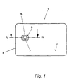
- the card body 1 shown in FIG. 1 in connection with FIG. 4 is in the essentially rectangular plate with a top 2, a bottom 3 and a provided by four side surfaces, peripheral edge 4.
- the top 2 has on the left side rectangular module recess 5, which is constructed from two paragraphs.
- the first Heel is the so-called carrier recess 6 with a depth of 0.2 mm, measured from the top 2 of the card body 1.
- a circular, deeper cap recess 7 provided with a depth of 0.6 mm.
- a Total wall thickness of the card body of 0.8 mm thus remains with a wall 8 the thickness of 0.2 mm.
- This card body 1 is printed on the top and / or bottom 2, 3 and then a chip module, not shown, is glued into the module recess 5.
- the carrier substrate of the chip module comes into contact with the carrier recess 6 and is connected to it while the microchip is encapsulated Cap recess 7 is located.
- On the side of the Carrier substrate are the externally visible contacts.
- a card body blank is shown, which by a Injection molding process is made.
- Several of these basic card body blanks are preferred produced in one mold at the same time, with each mold nest having one
- the valve gate is assigned.
- the plastic is injected vertically to the top 2 in the middle of the module recess 5.
- the module recess 5 is at the Injection molding process only to the depth of the carrier recess 6 and formed in it In the middle there remains a sprue point 9, the height of which is less than the depth of the Carrier recess 6.
- the injection mold, not shown, is corresponding to this molded. Characterized in that the cap recess 7 is not yet in the injection molding process is produced, a residual wall thickness to the underside 3 of 0.6 mm remains.
- This Wall thickness is greater than a critical limit of approx. 400 ⁇ m, which is decisive for the use or non-use of various plastics.
- the previously used Film sprues always had a lower cross-sectional height, which is why numerous, especially inexpensive, plastics could not be used.
- a processing tool 10 can both cutting tools, such as countersinks or milling cutters, as well as non-cutting tools Tools such as Embossing stamps can be used. At the same time such a postprocessing also completely removed the sprue point 9 since it is in the machining area of the tool.
- Post-processing i.e. incorporating the cap recess 7 and removing the Gate 9 can be before or after printing on the top and / or bottom 2, 3rd of the card body 1. Then the chip module in the Module recess 5 inserted and fastened in this. The capping of the chip module then fits into the cap recess 7 in a form-fitting manner.
Landscapes
- Engineering & Computer Science (AREA)
- Computer Hardware Design (AREA)
- Microelectronics & Electronic Packaging (AREA)
- Physics & Mathematics (AREA)
- General Physics & Mathematics (AREA)
- Theoretical Computer Science (AREA)
- Manufacturing & Machinery (AREA)
- Mechanical Engineering (AREA)
- Credit Cards Or The Like (AREA)
- Moulds For Moulding Plastics Or The Like (AREA)
- Injection Moulding Of Plastics Or The Like (AREA)
Abstract
Description
- Fig. 1
- einen Kartengrundkörper in einer Vorderansicht,
- Fig. 2
- einen Kartengrundkörper-Rohling zum Herstellen des Kartengrundkörpers aus Fig. 1,
- Fig. 3
- einen Schnitt entlang der Linie III-III aus Fig. 2 in einer vergrößerten Darstellung und
- Fig. 4
- einen Verfahrensschritt kurz nach der Fertigstellung der Modulaussparung aus Fig. 1 entlang der Linie IV-IV in Fig. 1 geschnitten und in einer vergrößerten Darstellung.
Claims (19)
- Verfahren zum Herstellen eines flachen Kartengrundkörpers (1) für eine Chipkarte, der eine Oberseite (2), eine Unterseite (3) und einen umlaufenden Rand (4) aufweist, bei dem über einen Anguß (9) Kunststoffmaterial in eine Spritzgußform eingespritzt, der Kartengrundkörper (1) aus der Spritzgußform entnommen und nachfolgend der Anguß (9) entfernt wird, dadurch gekennzeichnet, daß das Einspritzen über einen Anguß (9) an der Ober- und/oder Unterseite (2, 3) des Kartengrundkörpers (1) erfolgt.
- Verfahren nach Anspruch 1, dadurch gekennzeichnet, daß das Einspritzen des Kunststoffmaterials über einen kleinen Angußpunkt (9) erfolgt.
- Verfahren nach Anspruch 1 oder 2, dadurch gekennzeichnet, daß das Einspritzen des Kunststoffmaterials über einen Anguß (9) innerhalb einer Vertiefung (5) in der Ober- und/oder Unterseite (2, 3) des Kartengrundkörpers (1) erfolgt.
- Verfahren nach Anspruch 3, dadurch gekennzeichnet, daß die Höhe des Angußpunktes (9) gleich oder geringer ausgeführt wird, wie oder als die Tiefe der Vertiefung (5).
- Verfahren nach einem der Ansprüche 1 bis 4, bei dem während des Spritzgießens eine Modulaussparung (5) für das spätere Einsetzen des Chipmoduls eingeformt wird, dadurch gekennzeichnet, daß das Einspritzen über den Anguß (9) im Bereich der Modulaussparung (5) erfolgt.
- Verfahren nach Anspruch 5, durch das der fertigte Kartengrundkörper (1) eine mehrstufige Modulaussparung (5) erhält, die unterteilt ist in eine flache Trägeraussparung (6) und eine tiefere Kappenaussparung (7), dadurch gekennzeichnet, daß das Einspritzen über den Anguß (9) im Bereich der Trägeraussparung (6) erfolgt.
- Verfahren nach Anspruch 5, durch das der fertige Kartengrundkörper (1) eine mehrstufige Modulaussparung (5) erhält, die unterteilt ist in eine flache Trägeraussparung (6) und eine tiefere Kappenaussparung (7), dadurch gekennzeichnet, daß das Einspritzen über den Anguß (9) im Bereich der Kappenaussparung (7) erfolgt.
- Verfahren nach einem der Ansprüche 1 bis 7, dadurch gekennzeichnet, daß der Anguß (9) nach dem Spritzgießen spanabhebend entfernt wird.
- Verfahren nach einem der Ansprüche 1 bis 8, dadurch gekennzeichnet, daß der Anguß (9) durch das Einformen einer Modulaussparung (5) oder eines Bereiches davon entfernt wird.
- Verfahren nach Anspruch 9, dadurch gekennzeichnet, daß der Anguß (9) beim Ausformen einer Kappenaussparung (7) nach dem Spritzgießen entfernt wird.
- Verfahren nach einem der Ansprüche 2 bis 10, dadurch gekennzeichnet, daß der Angußpunkt (9) durch ein Nadelverschluß-Heißkanalangießen erzeugt wird.
- Verfahren nach einem der Ansprüche 2 bis 11, dadurch gekennzeichnet, daß der Angußpunkt (9) durch ein Punktangießen erzeugt wird.
- Vorrichtung zum Spritzgießen eines Kartengrundkörpers (1) für eine Chipkarte nach einem Verfahren gemäß einem der Ansprüche 1 bis 12, die eine Spritzgußform mit mindestens einem Formnest für den Kartengrundkörper (1) und einen dem jeweiligen Formnest zugeordneten Angußkanal zum Zuführen des Kunststoffmaterials aufweist, dadurch gekennzeichnet, daß der Angußkanal an einer Stelle in das Formnest mündet, die einer Ober- und/oder Unterseite (2, 3) des zu formenden Kartengrundkörpers (1) zugeordnet ist.
- Vorrichtung nach Anspruch 13, dadurch gekennzeichnet, daß die Spritzgußform im Bereich des Formnestes jeweils eine Erhöhung zum Ausformen einer Modulaussparung (5) aufweist und der Angußkanal im Bereich dieser Erhöhung mündet.
- Vorrichtung nach Anspruch 13 oder 14, dadurch gekennzeichnet, daß der Angußkanal eine Nadelverschluß-Heißkanaleinrichtung aufweist.
- Vorrichtung nach Anspruch 14 oder 15, dadurch gekennzeichnet, daß der Angußkanal eine Punktangußeinrichtung aufweist.
- Vorrichtung nach einem der Ansprüche 14 bis 16, dadurch gekennzeichnet, daß umlaufend um jedes Formnest Kanäle mit Entlüftungsschlitzen angeordnet sind.
- Kartengrundkörper-Rohling für eine Chipkarte, der durch ein Verfahren nach einem der Ansprüche 1 bis 12 hergestellt ist, gekennzeichnet durch einen Anguß (9) an der Ober- und/oder Unterseite (2, 3).
- Kartengrundkörper-Rohling nach Anspruch 18, dadurch gekennzeichnet, daß der Anguß in einer Modulaussparung (5) in der Ober- und/oder Unterseite (2, 3) angeordnet ist.
Applications Claiming Priority (2)
| Application Number | Priority Date | Filing Date | Title |
|---|---|---|---|
| DE19750344 | 1997-11-13 | ||
| DE19750344A DE19750344C2 (de) | 1997-11-13 | 1997-11-13 | Verfahren zum Herstellen eines flachen Kartengrundkörpers für eine Chipkarte |
Publications (2)
| Publication Number | Publication Date |
|---|---|
| EP0917100A2 true EP0917100A2 (de) | 1999-05-19 |
| EP0917100A3 EP0917100A3 (de) | 1999-05-26 |
Family
ID=7848641
Family Applications (1)
| Application Number | Title | Priority Date | Filing Date |
|---|---|---|---|
| EP98120326A Withdrawn EP0917100A3 (de) | 1997-11-13 | 1998-10-27 | Verfahren zum Herstellen eines flachen Kartengrundkörpers für eine Chipkarte |
Country Status (2)
| Country | Link |
|---|---|
| EP (1) | EP0917100A3 (de) |
| DE (1) | DE19750344C2 (de) |
Cited By (1)
| Publication number | Priority date | Publication date | Assignee | Title |
|---|---|---|---|---|
| WO2017066464A1 (en) | 2015-10-14 | 2017-04-20 | Capital One Services, Llc | Molded pocket in transaction card construction |
Family Cites Families (7)
| Publication number | Priority date | Publication date | Assignee | Title |
|---|---|---|---|---|
| FR2605144B1 (fr) * | 1986-10-14 | 1989-02-24 | Flonic Sa | Procede de realisation de cartes a memoire electronique et cartes obtenues par la mise en oeuvre dudit procede |
| FR2650530B1 (fr) * | 1989-08-07 | 1991-11-29 | Schlumberger Ind Sa | Procede de realisation de corps de carte avec graphisme |
| DE4115208C2 (de) * | 1991-05-10 | 1994-06-30 | Wilden Engineering Gmbh | Verfahren und Vorrichtung zum Herstellen von Kunststoff-Formstücken mit bereichsweise reduzierter Wandstärke |
| JP3075296B2 (ja) * | 1991-05-27 | 2000-08-14 | 大日本印刷株式会社 | Icカード用カード基材の製造方法及び製造用金型 |
| FR2695854B1 (fr) * | 1992-09-22 | 1994-12-09 | Leroux Ets Gilles | Dispositif de fraisage de cavités dans des cartes en matière plastique et d'encartage de circuits intégrés dans lesdites cavités. |
| DE4432017C2 (de) * | 1994-09-08 | 1998-02-05 | Techno Finish Gmbh | Verfahren und Vorrichtung zur Herstellung von Zifferblättern |
| JPH09174612A (ja) * | 1995-12-22 | 1997-07-08 | Victor Co Of Japan Ltd | Icカード用基材の射出成形方法及びその金型 |
-
1997
- 1997-11-13 DE DE19750344A patent/DE19750344C2/de not_active Expired - Fee Related
-
1998
- 1998-10-27 EP EP98120326A patent/EP0917100A3/de not_active Withdrawn
Cited By (3)
| Publication number | Priority date | Publication date | Assignee | Title |
|---|---|---|---|---|
| WO2017066464A1 (en) | 2015-10-14 | 2017-04-20 | Capital One Services, Llc | Molded pocket in transaction card construction |
| EP3362248A4 (de) * | 2015-10-14 | 2019-05-08 | Capital One Services, LLC | Geformte tasche in einer transaktionskartenkonstruktion |
| US11034065B2 (en) | 2015-10-14 | 2021-06-15 | Capital One Services, Llc | Molded pocket in transaction card construction |
Also Published As
| Publication number | Publication date |
|---|---|
| DE19750344C2 (de) | 2000-05-18 |
| DE19750344A1 (de) | 1999-06-02 |
| EP0917100A3 (de) | 1999-05-26 |
Similar Documents
| Publication | Publication Date | Title |
|---|---|---|
| EP0584143B2 (de) | Verfahren und vorrichtung zum herstellen von kunststoff-formstücken mit bereichsweise reduzierter wandstärke | |
| EP2651598B1 (de) | Zum einspannen einer turbinenschaufel eingerichtete einrichtung und turbinenschaufel | |
| EP2502723B1 (de) | Verfahren zur Herstellung von faserverstärkten, Anbauelemente umfassenden Innenverkleidungsbauteilen für Kraftfahrzeuge | |
| EP1938944A1 (de) | Verfahren zur Herstellung eines mehrschichtigen Kunststoffkörpers | |
| EP1655122B1 (de) | Verfahren zum Hinterspritzen, Hinterpressen oder Quellflussprägen und entsprechendes Formwerkzeug | |
| EP0721832A2 (de) | Verfahren zur Herstellung von verhältnismässig dickwandigen Bürstenkörpern, insbesondere von Zahnbürsten aus thermoplastischem Kunststoff | |
| DE112014004575T5 (de) | Formwerkzeug zum Umspritzen eines Verbundeinsatzteiles und entsprechendes Umspritzungsverfahren | |
| DE69315172T2 (de) | Verfahren zum in Kunststoff einzugiessender Metalleinlage | |
| EP3222399B1 (de) | Vorrichtung und verfahren zum herstellen eines formpressteils, welches mindestens einen durchbruch aufweist | |
| DE19729486C2 (de) | Verfahren zur Herstellung eines Kunststoffteiles und Vorrichtung zur Durchführung des Verfahrens | |
| DE102004020085A1 (de) | Verfahren zur Herstellung eines kunststoffumspritzten Stanzgitters und kunststoffumpritztes Stanzgitter | |
| EP0548857A1 (de) | Vorrichtung zum Herstellen von flachen Kunststoff-Formstücken, beispielsweise Ausweiskarten | |
| DE19750344C2 (de) | Verfahren zum Herstellen eines flachen Kartengrundkörpers für eine Chipkarte | |
| DE19736082C1 (de) | Verfahren und Herstellen einer Chipkarte und Vorrichtung zur Durchführung des Verfahrens | |
| DE102007001756B4 (de) | Verfahren und Spritzgussform zum Spritzgießen von hohlen Formteilen aus Kunststoff | |
| DE2346181C3 (de) | Verfahren zur Herstellung eines Leistens für die Schuhherstellung, sowie Gießform hierfür | |
| DE69937635T2 (de) | Verfahren zur herstellung einer mit kontakten versehenen ic-karte und nach diesem verfahren hergestellte ic-karte | |
| EP1046486B1 (de) | Formwerkzeug zur Herstellung von mehreren montagegespritzten Bauteilen | |
| DE202011108698U1 (de) | Vorrichtung zur Erzeugung einer abgießbaren Markierung an einem Kern oder an einer Gießform für den Abguss eines Gießteiles | |
| EP1737637A1 (de) | Vorrichtung zum teilweisen umspritzen metallischer einleger mit einem spritzgiesswerkzeug | |
| DE10148525B4 (de) | Chipkarte sowie ein Verfahren zur Herstellung einer derartigen Chipkarte | |
| EP1952963A1 (de) | Spritzgießen eines Auskleidungsteils für Motorfahrzeuge | |
| DE102004056451A1 (de) | Werkzeug und Verfahren zur Herstellung von Formkörpern mit Öffnungen | |
| EP0853812B1 (de) | Verfahren und vorrichtung zur endmontage einer computer-tastatur | |
| EP1440782B1 (de) | Vorrichtung und Verfahren zur Herstellung von aus Kunststoff bestehenden Gegenständen (Kunststoffbauteilen) mittels Fliessbremsen in Spritzgusswerkzeugen und deren Verwendung |
Legal Events
| Date | Code | Title | Description |
|---|---|---|---|
| PUAI | Public reference made under article 153(3) epc to a published international application that has entered the european phase |
Free format text: ORIGINAL CODE: 0009012 |
|
| PUAL | Search report despatched |
Free format text: ORIGINAL CODE: 0009013 |
|
| AK | Designated contracting states |
Kind code of ref document: A2 Designated state(s): AT CH DE DK ES FR GB IE IT LI NL SE |
|
| AX | Request for extension of the european patent |
Free format text: AL;LT;LV;MK;RO;SI |
|
| AK | Designated contracting states |
Kind code of ref document: A3 Designated state(s): AT BE CH CY DE DK ES FI FR GB GR IE IT LI LU MC NL PT SE |
|
| AX | Request for extension of the european patent |
Free format text: AL;LT;LV;MK;RO;SI |
|
| 17P | Request for examination filed |
Effective date: 19990709 |
|
| AKX | Designation fees paid |
Free format text: AT CH DE DK ES FR GB IE IT LI NL SE |
|
| RAP1 | Party data changed (applicant data changed or rights of an application transferred) |
Owner name: GEMPLUS GMBH |
|
| 17Q | First examination report despatched |
Effective date: 20040908 |
|
| STAA | Information on the status of an ep patent application or granted ep patent |
Free format text: STATUS: THE APPLICATION IS DEEMED TO BE WITHDRAWN |
|
| 18D | Application deemed to be withdrawn |
Effective date: 20050319 |