EP0917103A2 - Bildverarbeitung - Google Patents
Bildverarbeitung Download PDFInfo
- Publication number
- EP0917103A2 EP0917103A2 EP98309051A EP98309051A EP0917103A2 EP 0917103 A2 EP0917103 A2 EP 0917103A2 EP 98309051 A EP98309051 A EP 98309051A EP 98309051 A EP98309051 A EP 98309051A EP 0917103 A2 EP0917103 A2 EP 0917103A2
- Authority
- EP
- European Patent Office
- Prior art keywords
- image
- current image
- camera
- transformation
- images
- Prior art date
- Legal status (The legal status is an assumption and is not a legal conclusion. Google has not performed a legal analysis and makes no representation as to the accuracy of the status listed.)
- Withdrawn
Links
Images



Classifications
-
- G—PHYSICS
- G06—COMPUTING OR CALCULATING; COUNTING
- G06T—IMAGE DATA PROCESSING OR GENERATION, IN GENERAL
- G06T7/00—Image analysis
- G06T7/80—Analysis of captured images to determine intrinsic or extrinsic camera parameters, i.e. camera calibration
-
- G—PHYSICS
- G06—COMPUTING OR CALCULATING; COUNTING
- G06T—IMAGE DATA PROCESSING OR GENERATION, IN GENERAL
- G06T7/00—Image analysis
- G06T7/70—Determining position or orientation of objects or cameras
-
- H—ELECTRICITY
- H04—ELECTRIC COMMUNICATION TECHNIQUE
- H04N—PICTORIAL COMMUNICATION, e.g. TELEVISION
- H04N23/00—Cameras or camera modules comprising electronic image sensors; Control thereof
- H04N23/60—Control of cameras or camera modules
- H04N23/68—Control of cameras or camera modules for stable pick-up of the scene, e.g. compensating for camera body vibrations
-
- H—ELECTRICITY
- H04—ELECTRIC COMMUNICATION TECHNIQUE
- H04N—PICTORIAL COMMUNICATION, e.g. TELEVISION
- H04N23/00—Cameras or camera modules comprising electronic image sensors; Control thereof
- H04N23/60—Control of cameras or camera modules
- H04N23/68—Control of cameras or camera modules for stable pick-up of the scene, e.g. compensating for camera body vibrations
- H04N23/681—Motion detection
- H04N23/6811—Motion detection based on the image signal
-
- H—ELECTRICITY
- H04—ELECTRIC COMMUNICATION TECHNIQUE
- H04N—PICTORIAL COMMUNICATION, e.g. TELEVISION
- H04N23/00—Cameras or camera modules comprising electronic image sensors; Control thereof
- H04N23/60—Control of cameras or camera modules
- H04N23/68—Control of cameras or camera modules for stable pick-up of the scene, e.g. compensating for camera body vibrations
- H04N23/682—Vibration or motion blur correction
-
- H—ELECTRICITY
- H04—ELECTRIC COMMUNICATION TECHNIQUE
- H04N—PICTORIAL COMMUNICATION, e.g. TELEVISION
- H04N23/00—Cameras or camera modules comprising electronic image sensors; Control thereof
- H04N23/60—Control of cameras or camera modules
- H04N23/68—Control of cameras or camera modules for stable pick-up of the scene, e.g. compensating for camera body vibrations
- H04N23/682—Vibration or motion blur correction
- H04N23/685—Vibration or motion blur correction performed by mechanical compensation
- H04N23/687—Vibration or motion blur correction performed by mechanical compensation by shifting the lens or sensor position
Definitions
- the present invention relates, to image processing.
- Embodiments of the invention relate to a method and apparatus for fixating a camera on a target point using image alignment.
- a common problem is how to keep the camera centered on a stationary target in the scene. Such centering is desirable, because it results in the video looking stable and, therefore, easy to watch; video that does not stay locked on a point contains significant motions due to the moving platform. The motion makes the video look "jittery" and may even cause most of the desired scene to move out of the image sporadically. This problem is especially acute in situations where the field of view is narrow and the camera platform is subject to sudden changes in orientation, such as airborne surveillance.
- fixating The task of keeping a camera centered on a point is commonly referred to as "fixating" a point.
- Traditional approaches to fixating a point have primarily relied on mechanical stabilization to hold the camera steady.
- these approaches use gyroscopes to sense rotation of the camera platform, and motors to compensate for that rotation.
- gyroscopes to sense rotation of the camera platform, and motors to compensate for that rotation.
- the cost of such systems increases rapidly depending on the number of rotational axes, and the desired precision of the stabilization.
- Recent approaches have added an electronic image matching device to supplement mechanical stabilization.
- the device operates on a small image region (typically of size 32 x 32 pixels) around the image center, and uses correlation matching to estimate the translational image motion of this region from one video frame to the next. With correlation matching, the amount of "image slip" may be measured.
- Image slip is the distance through which the center of the current image moves from the desired fixation point.
- This image slip may be converted to an angular correction and applied to a motorized pan/tilt camera mount in order to re-center the camera on the desired fixation point. In this manner, fixation may be achieved by a combination of mechanical stabilization and closed-loop pan/tilt control that uses correlation matching to measure the image slip.
- Burt et al. Object tracking with a moving camera: an Application of Dynamic Motion Analysis," IEEE Workshop on Visual Motion, Irvine California, March 1989. Burt et al. teaches that if the camera is moving, it is often possible to compensate for resulting image motion by electronically shifting and rotating successive image frames to achieve alignment prior to computing a frame difference. Electronic alignment is based on a simple image warp (e.g., based on an affine transform) that is effective when scene motion contains relatively little parallax, such as when the camera is rotating, but not translating, or when objects within the region of the camera's field of view occur in a relatively narrow range of depths.
- a simple image warp e.g., based on an affine transform
- the image alignment technique of the present invention is directed to overcoming the problem of fixation, especially in the presence of motor latencies.
- Embodiments of the present invention provide a method and apparatus for fixating a camera on a target point using image alignment.
- the method includes the following steps:
- FIG. 1 is a block diagram of an apparatus for fixating a camera on a target using digital image processing techniques.
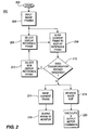
- FIG. 2 is a flow diagram of a method for fixating a camera on a target using display reference frames for alignments.
- FIG. 3 is a flow diagram of a method for fixating a camera on a target using display reference frames and targeting reference frames for alignment.
- FIG. 4 is a flow diagram of a method for adding targeting reference frames to an existing database containing targeting reference frames.
- FIG. 1 depicts a block diagram of illustrative apparatus 100 for fixating a camera on a target suitable for implementing the present invention.
- the apparatus contains image source 102 stabilised on gimballed mount 106, computer system 104, one or more output devices 124 and one or more input devices 126.
- Image source 102 may be a video camera, an infrared camera, or some other sensor that generates a series of two-dimensional images representing a scene.
- the apparatus generally processes digital images; therefore, if the image source produces analog images, a digitizer (not shown) may be used between the image source and the computer system.
- General purpose computer 104 facilitates image processing, scene analysis and image display.
- the computer system contains a data buffer 110, a central processing unit (CPU) 112, support circuitry 114, random access memory (RAM) 116, read only memory (ROM) 118, display driver 120, and input/output buffer 108.
- a user may interact with the computer system through one or more input devices 126 such as a keyboard, mouse, trackball, touchpad, and the like.
- the computer system displays the images on output device 124 such as a computer monitor.
- the computer system may also interact with other output devices such as an image processing system, which may, for example, convert a segment of image into a television signal or a printer to provide a "hard copy" of any display that appears on the computer monitor.
- Data buffer 110 provides data rate equalization (frame buffering) between the image source and the CPU.
- this buffer is a first-in, first-out (FIFO) buffer.
- FIFO first-in, first-out
- Such buffers are typically used to provide a constant data rate to the CPU while providing flexibility in the data rates that can be generated by an image source.
- CPU 112 is typically a general purpose processor such as Power PC, Pentium, or some other generally available processor.
- PowerPC is a register trademark of International Business Machines of Armonk, New York
- Pentium is a registered trademark of Intel Corporation of Santa Clara, California. Since the software implementation of the present embodiment is not required to execute on any specific processor, the routines of the present embodiment can be executed upon any type of processor or combination of processors in a parallel processing computer environment. In addition, rather than using a general purpose computer, the scene analysis may be accomplished within a real-time image processor.
- CPU 112 operates in conjunction with various other circuits such as RAM 116, ROM 118 and support circuitry 114 such as co-processor(s), clock circuits, cache, power supplies and other well-known circuits.
- Support circuitry may also include specialized hardware for accelerating image processing such as image warpers or filtering circuitry.
- One such filtering chip is the PYR-1 circuit described by van der Wal et al. in U.S. Patent No. 5,561,617. The operation and interrelationship of these various computer components is well-known in the art and does not require further explanation.
- the display driver 120 may be a video card, printer driver or other common driver software or hardware as required by output device(s) 124.
- RAM 116 stores the software implementation of the present embodiment.
- routines of the embodiment are stored in a mass storage device (not shown) and recalled for temporary storage in RAM 116 when executed by CPU 112.
- the illustrative image alignment routine is indicated at 122 in the RAM.
- I/O buffer 108 provides the appropriate data interface between computer system 104 and gimbaled mount 106. It will be appreciated that I/O buffer 108 may reside in side the computer system or externally to the computer system.
- Image alignment routine 122 provides control signals to gimbaled mount 106 to correct its spatial alignment so that the viewing angles of image source 102 may be repositioned in pan or tilt. This may be done with a conventional proportional-integral (PI) negative feedback loop wherein the pan and tilt motors (not shown) of mount 106 are commanded to achieve a velocity proportional to this correction.
- PI proportional-integral
- Image alignment routine 122 is now described starting with definitions.
- the scene surface used in computing alignment is the "target surface” and its image in the camera is the “target image.”
- a point on the target surface to which the camera is to be centered (fixated) is the “target point.”
- the target surface may be all of the scene that is within the field of view of the camera and the target point may be assumed to be on the target surface.
- Fixation starts with an image in which the desired fixation point is a known image coordinate (for example, the image center). This image could be provided by the operator, or could come from other sources, as is described below. This image is the reference image.
- Image alignment routine 122 relies on a sequence of video frames from image source 102 taken from different viewpoints.
- the sequence of video frames may be written as ⁇ F 0 ,F 1 ,F 2 ,...F i ,F j ,...F c ,...F n ⁇ where F o is the display reference frame and F c is the current frame.
- the alignment reference frame is replaced by the current frame whenever r / cM indicates that "significant" image displacements have occurred. It will be appreciated that this may occur whenever the average pixel motion exceeds 5 pixels.
- the specific parametric transformation to be used may depend on the type of scene being viewed and the motion of the camera.
- the most typical transformations used are translational (consisting of 2 parameters, one for each image translation in two orthogonal coordinate directions aligned with the image) and affine (consisting of 6 parameters).
- This estimate does not necessarily have to be obtained by directly aligning the current frame with the reference frame. It may also be obtained by estimating the alignment between consecutive video image frames, starting with the image that was used as the reference frame. Given such a set of frame-to-frame alignments, the alignment between the current image and the reference image may be derived by cascading the frame-to-frame alignments in sequence.
- Image alignment has been described by L. Wixson, J. Eledath, M. Hansen, R. Mandelbaum, and D. Mishra, in “Image Alignment for Precise Camera Fixation and Aim, " Proceedings of the IEEE Conference on Computer Vision and Pattern Recognition (June 1998).
- the o / rM estimate is updated by setting it to o / cM.
- o / cM becomes large, it is often useful to reset the display reference frame to avoid confusing a human observer; the display reference should bear some obvious resemblance to the current view.
- the display reference F 0 and the alignment reference F r are both set to be the current frame, and 0 / rM and r / cM are both set to identity. This is described in detail below.
- the image motion between frames j / iM may be modeled as a 3 x 3 matrix, as shown in equation (2) that warps points (x',y',1) in frame F i to points (x"y"1) in F j , where Similarly for y" where j / iM k denotes the k'th row of matrix j / iM.
- equation (2) that warps points (x',y',1) in frame F i to points (x"y"1) in F j , where Similarly for y" where j / iM k denotes the k'th row of matrix j / iM.
- different parametric motion models may be used. For example, when g and h are forced to 0, j / iM is an affine transform.
- an aircraft may fly a rough ellipse around the target point, resulting in an oblique view of the ground plane.
- the affine motion is estimated using the above referenced real-time multi-resolution image alignment procedure described in M. Hansen et al. Shown therein is the utility of the affine model to align two oblique views, while the camera is translating, panning and zooming.
- Fixation is achieved by combining closed-loop control of the camera, shown in FIG. 1 as closed-loop control line 107, with electronic stabilization.
- the control loop is driven by measuring a centering error e, i.e. the image distance between the center of the current frame F c and the position of the point corresponding to the center of the display reference frame F o , as shown in equation (3). when using image coordinate systems in which the image center is ⁇ 0,0>.
- the matrix c / 0M may be obtained by inverting 0 / cM, which was computed as part of the electronic stabilization process.
- the centering error e can be translated into pan and tilt corrections using knowledge of the kinematic chain mapping the pan and tilt spaces to image coordinates.
- PI proportional-integral
- the pan and tilt motors may be commanded to achieve a velocity proportional to this correction.
- Simple PI control suffices due to the electronic stabilization that is performed in conjunction with fixation. This provides a stable view even if the fixation motor control loop may lag or oscillate due to measurement and actuator latencies, or turbulence of the camera platform.
- augmenting motor fixation with electronic stabilization is advantageous because typical motor configurations allow control only over the camera pan and tilt and can, therefore, stabilize a scene only when the image motion is translational, i.e., when there is no camera rotation about the optical axis.
- Electronic image alignment can compensate for more complex camera motion and can hold the dominant surface in the image stationary, leaving only residual motion due to parallax and independent motion. This greatly facilitates the observation of fine scene details, whether by a human or by vision processing.
- a further advantage of electronic stabilization is that it allows a human operator to specify new fixation points within the field of view using a stable display. This aids operator interaction with the system.
- Changing the fixation point may be performed by imposing a new display reference frame, which is shifted from the old frame by a user-specified ⁇ x and ⁇ y .
- This shift can be imposed on the stabilization and fixation processes, by changing the transform 0 / rM that maps the alignment reference to the display reference frame.
- This new transform, o / rM' is shown in equation (4).
- the original fixation point can be brought to the center of the new display reference frame by shifting the new display reference by e, as described above.
- This fixation on the target may be maintained by setting 0 / rM', as shown in equation (5).
- FIG. 2 depicts a flow diagram of a method for fixating a camera on a target point using image alignment.
- the method is represented as an executable software routine 200 that begins at step 202 and proceeds to step 220. Steps 206-220 are repeated on each iteration of the control loop.
- the routine is provided with a plurality of input image frames.
- a display reference frame is selected.
- the current frame is aligned to the display reference frame, as previously described.
- the magnitude of the coefficients of the parametric transformation that maps the current frame to the display reference frame is examined. If the magnitude of selected coefficients (e.g., those corresponding to image rotation) is larger than some predetermined threshold, the display reference frame is replaced with the current reference frame in step 210.
- the coordinates of the fixation point in the new display reference frame is based on the coordinates of the fixation point in the previous display reference frame and the estimated transformation between the current frame and the previous frame, as previously described.
- mapping from current to reference images is obtained, then by inverting this transform, via straightforward mathematics, the mapping from reference frame to current frame may be obtained.
- image coordinates of the fixation point in the reference image the image coordinates of the fixation point in the current frame is computed.
- the image slip between the current frame and the reference frame is computed by subtracting the coordinates of the fixation point in the reference frame from the coordinates of the fixation point in the current frame.
- image slip may be computed by transforming the first coordinate location into the coordinate system of the current image using the estimated mapping, and then subtracting the resulting location from the location of the center point or other specified point in the current image. Having computed image slip in step 218, motor commands are calculated and provided as an output in step 220.
- the image slip may be converted to camera angular and position corrections that will re-align the camera so that the image coordinate of the fixation point in subsequent imagery will match that in the reference frame.
- the motors may be commanded to achieve this correction using either position control or velocity control, two well-known concepts in robotics and control theory.
- the fixation system operates in a closed loop configuration, using control laws such as PID or Kalman-filter-based laws, again according to principles from closed-loop feedback control.
- the computed image mapping from current frame to reference frame may also be used to electronically stabilize the current frame. This is accomplished in step 214 by warping the current frame by the computed parametric image transformation. This warped image may be sent, in step 216, to either a display for viewing or to further image processing steps.
- Warping may stabilize the scene in ways that are not achievable with mechanical techniques or translation-only motion estimation. Specifically, it may compensate for image rotations corresponding to rotations of the camera platform around axes that may not be stabilized in all mechanical stabilization systems. Further, it may compensate for image scaling and skewing due to translation of the camera platform or zooming of the camera.
- electronic stabilization can make the camera appear to be fixating perfectly even when the camera closed-loop control is not perfect. This is important because perfect closed-loop control is often difficult due to imprecision on the pan/tilt position encoders, latencies in error measurement, long communications latencies between the time a motor command is issued and the time it is executed by the pan/tilt motors, and turbulence of the camera platform.
- the reference image (frame) is varied.
- the reference image may be obtained by simply grabbing the current image at certain time instants. This is for the benefit of a human viewer. As the platform moves, the scene perspective changes. (Consider for example, an airplane flying circles or ellipses around a fixation point on the ground.) In order for the human viewer to be able to view the stabilized output, but still have the reference coordinate system be somewhat similar to his current coordinate system, the reference image must be periodically replaced. Another reason for replacing the reference image may be to prevent the magnitude of the parametric transformation from exceeding the capabilities of a limited hardware image warper.
- the algorithm shown in FIG. 2 is one embodiment of this invention, using fixation based purely on display reference images (frames).
- the fixation point may "drift" off the desired point. This drift is due to small errors in the image alignment that may accumulate every time the display reference is replaced, specifically when the coordinates of the fixation point in the new display reference image are computed. It may be desirable, therefore, to add a second type of reference image the "target" reference image.
- a "target" reference image may be used in place of the "display” reference image to reset the fixation point to the desired point.
- computer system 104 may store a collection of target reference images.
- the current frame may be added to the collection, if selected coefficients of the transformation between the current frame and the original frame, obtained at the start of fixation, exceed some threshold and there is no target reference image already in the collection that has a similar transformation.
- the computer system may accumulate a set of target reference images that reflect the changes in viewpoint as the camera is fixating.
- the camera platform may be moving on a repeating course, such as an aircraft flying circles or ellipses around a fixation point.
- target reference images that are similar to the current image.
- the best (i.e. most similar) target reference may be located by comparing the current estimated image transform relative to the starting frame to that transform stored with each target reference.
- the display reference may be aligned to that target reference so that the fixation point in the display reference may be reset to lie on the same 3D point as that fixation point in the target reference.
- executable software routine 300 receives a plurality of input images (frames) by way of input line 326. These input images are provided to modules 304 and 308.
- Module 308 aligns the current image with a display reference image, as was described previously for executable software routine 200 of FIG. 2. If it is determined by module 322 which the magnitude of the coefficients of the parametric transformation which maps the current image to the display reference image is larger than some predetermined threshold, the display reference image is replaced with the current reference image.
- Image slip is measured by module 324 and converted into motor commands by module 314.
- motorized camera mount 312 is mechanically aligned by way of feedback control loop line 328.
- module 316 electronically warps the current image so it is aligned with the display reference image. The image is sent to TV monitor 318 or it may be sent to another module (not shown) for further image processing. All of these modules are similar to the modules described above.
- a collection of target reference images may exist in a database (not shown). From this collection, module 302 selects a target reference image. This could be performed, for example, as follows. Suppose that associated with each target reference image t is a transformation f / tM that aligns it to the original frame f , i.e. the initial frame f when the fixation process was initially begun. Also suppose that a similar transform f / cM is computed that aligns the current frame c to the initial frame.
- Module 302 could select the target reference image t whose transform f / tM is most similar to f / cM.
- module 304 electronically aligns the display reference image to the target reference image.
- the alignment process performed by module 304 is similar mathematically to the alignment process performed by module 308. Since the desired fixation point in the target reference is known from the database, then the fixation point coordinates in the display reference can be reset by module 320, using the computed alignment, to lie on the same 3D point as that fixation point in the target reference.
- Module 322 provides the display reference image along with the new fixation point in that image to modules 304 and 308. Image slip is measured by module 324 and output to module 314 for mechanical alignment of motorized camera mount 312.
- executable software routine 400 starts the method with step 402 and is provided with a set of input image frames into module 406, in the same manner as described earlier.
- Module 408 selects a targeting reference image from database 404.
- a parametric transformation that maps the current image (from the input image frames) to the selected targeting reference image is obtained in module 410.
- Parametric transformations are obtained between the current image and each of the other targeting reference images in the database. If the coefficients of the transformation exceed a predetermined threshold as determined by module 412, then the current image is added to the database collection by module 414.
- the method of warping the current frame to the selected targeting reference image performed by module 416 and the method of measuring image slip and computing angular motor commands performed by module 418 are the same as the methods described above.
- the camera In order for the camera to fixate a target, it must first acquire the target in its field of view. In many situations, the 3D coordinates of the target point as well as the camera pose are both known approximately. As a result, the camera may be pointed approximately at the target point simply by using the kinematic chain. A method for refining this aim (using the targeting reference mechanism) by aligning the resulting image to a database view of the scene in which the location of the target is known is now described.
- the geodetic coordinates of a desired target In airborne surveillance scenarios, it is common for the geodetic coordinates of a desired target to be known from GPS or photogrammetry. Similarly, the aircraft's geodetic position and orientation are known, respectively, from on-board GPS and AHRS (Attitude Heading Reference System) devices.
- GPS Global System for Mobile Communications
- the first step transforms target and aircraft geodetic coordinates to a 3D local vertical coordinate system (LVCS) that is referred to herein as the world coordinate system W .
- LVCS 3D local vertical coordinate system
- the target world coordinates W p and aircraft world coordinates W a may be obtained. These may be represented homogeneously as 4 x 1 vectors whose fourth element is 1. In this world coordinate system, the X axis points east, the Y axis north, and Z axis points up.
- a 4 x 4 matrix, A / WM that maps homogeneous world coordinates to an aircraft-centered coordinate system is defined by equation (6): where R x,y,z denotes clockwise rotation around the X, Y, or Z axes, respectively, and ⁇ r , ⁇ p , and ⁇ h , are the roll, pitch, and heading measured by the AHRS unit.
- the target world coordinates W p must be transformed into the coordinate system of the camera turret T p.
- the turret coordinate system is the coordinate system with respect to which the camera pans and tilts. It is different from the aircraft coordinate system because it is almost mechanically impossible to mount the turret with its baseplate exactly parallel to the AHRS axes; a small relative orientation offset is usually present. This offset is significant when aiming at targets using a narrow field of view.
- T / AM a 4 x 4 matrix that maps the aircraft coordinate system to the turret coordinate system, must be estimated.
- the above described camera aim may be improved through the illustrative image alignment method and apparatus of this invention.
- imagery of the target, coupled with associated aircraft pose when the imagery was acquired is available in advance from prior surveillance missions.
- the target location may be specified off-line by hand.
- a database image F d may be warped to predict how the scene would appear given the current camera pose. To do so, mapping is performed from world coordinates to image coordinates and vice versa.
- the symbol ⁇ is used herein to denote the set of viewing parameters consisting of position W a, orientation ⁇ r , ⁇ p , ⁇ h , pan ⁇ , tilt ⁇ , and focal length f .
- the i / WL matrix may be inverted as follows: where m is a null vector of i / WL, M * is the 4x3 right inverse of i / wL, and n is the 4x1 normal vector that defines the planar surface in world coordinates.
- F p is defined as the prediction image obtained by warping the database image Fd by i / dM. If there were no latencies or calibration errors in measuring the viewing parameters, and if the scene met the assumption of planarity, F p would be identical to the current image F i . In practice, however, there is still a substantial misalignment between F i and F p .
- the perspective effects on the ground plane are appropriately modeled, but there is often a significant translational offset between the two. This is because, in airborne scenarios with the target a long distance away, camera pan and tilt may change very rapidly and accurate measurement of these angles will be impaired by latency.
- the predicted image is synthesized from a previous image using known information about the position and orientation of the camera at the time the previous image was taken, as well as the current position and orientation of the camera. It is important to note that the predicted image may similarly be synthesized from a mosaic image which is constructed from multiple previous images, a geometric database model of the scene, an elevation map of the scene, or some combination of all of these.
Landscapes
- Engineering & Computer Science (AREA)
- Multimedia (AREA)
- Signal Processing (AREA)
- Computer Vision & Pattern Recognition (AREA)
- Physics & Mathematics (AREA)
- General Physics & Mathematics (AREA)
- Theoretical Computer Science (AREA)
- Studio Devices (AREA)
- Image Processing (AREA)
- Stereoscopic And Panoramic Photography (AREA)
- Length Measuring Devices By Optical Means (AREA)
- Closed-Circuit Television Systems (AREA)
Applications Claiming Priority (6)
| Application Number | Priority Date | Filing Date | Title |
|---|---|---|---|
| US6519097P | 1997-11-12 | 1997-11-12 | |
| US65190P | 1997-11-12 | ||
| US8202298P | 1998-04-16 | 1998-04-16 | |
| US82022P | 1998-04-16 | ||
| US143910 | 1998-08-31 | ||
| US09/143,910 US6396961B1 (en) | 1997-11-12 | 1998-08-31 | Method and apparatus for fixating a camera on a target point using image alignment |
Publications (2)
| Publication Number | Publication Date |
|---|---|
| EP0917103A2 true EP0917103A2 (de) | 1999-05-19 |
| EP0917103A3 EP0917103A3 (de) | 2003-09-24 |
Family
ID=27370746
Family Applications (1)
| Application Number | Title | Priority Date | Filing Date |
|---|---|---|---|
| EP98309051A Withdrawn EP0917103A3 (de) | 1997-11-12 | 1998-11-05 | Bildverarbeitung |
Country Status (3)
| Country | Link |
|---|---|
| US (1) | US6396961B1 (de) |
| EP (1) | EP0917103A3 (de) |
| JP (1) | JPH11252440A (de) |
Cited By (10)
| Publication number | Priority date | Publication date | Assignee | Title |
|---|---|---|---|---|
| WO2004068403A2 (en) | 2003-01-17 | 2004-08-12 | The Insitu Group | Cooperative nesting of mechanical and electronic stabilization for an airborne camera system |
| EP1436800A4 (de) * | 2001-10-19 | 2005-12-21 | Accenture Global Services Gmbh | Industrielle ergänzte realität |
| EP1983485A3 (de) * | 2004-09-15 | 2009-01-07 | Raytheon Company | FLIR-Rakete-Achsenkorrelation und Ungleichförmigkeitskompensation eines Raketensuchers |
| EP2242250A1 (de) * | 2009-04-16 | 2010-10-20 | Raytheon Company | Selbstkorrigierendes adaptives elektrooptisches Weitsichtsystem |
| US7822224B2 (en) | 2005-06-22 | 2010-10-26 | Cernium Corporation | Terrain map summary elements |
| US8345923B2 (en) | 2000-02-04 | 2013-01-01 | Cernium Corporation | System for automated screening of security cameras |
| US8405723B2 (en) | 2003-01-17 | 2013-03-26 | Insitu, Inc. | Compensation for overflight velocity when stabilizing an airborne camera |
| US8473200B1 (en) * | 2004-10-25 | 2013-06-25 | A9.com | Displaying location-specific images on a mobile device |
| WO2017027453A1 (en) * | 2015-08-07 | 2017-02-16 | Google Inc. | Controlling a line of sight angle of an imaging platform |
| US10341565B2 (en) | 2016-05-10 | 2019-07-02 | Raytheon Company | Self correcting adaptive low light optical payload |
Families Citing this family (62)
| Publication number | Priority date | Publication date | Assignee | Title |
|---|---|---|---|---|
| US6816184B1 (en) * | 1998-04-30 | 2004-11-09 | Texas Instruments Incorporated | Method and apparatus for mapping a location from a video image to a map |
| DE10025110C2 (de) * | 2000-05-20 | 2003-01-16 | Zsp Geodaetische Sys Gmbh | Verfahren und Vorrichtung zur Realisierung eines Informations- und Datenflusses für geodätische Geräte |
| US8711217B2 (en) * | 2000-10-24 | 2014-04-29 | Objectvideo, Inc. | Video surveillance system employing video primitives |
| US8564661B2 (en) | 2000-10-24 | 2013-10-22 | Objectvideo, Inc. | Video analytic rule detection system and method |
| US9892606B2 (en) | 2001-11-15 | 2018-02-13 | Avigilon Fortress Corporation | Video surveillance system employing video primitives |
| US8457401B2 (en) * | 2001-03-23 | 2013-06-04 | Objectvideo, Inc. | Video segmentation using statistical pixel modeling |
| US7424175B2 (en) | 2001-03-23 | 2008-09-09 | Objectvideo, Inc. | Video segmentation using statistical pixel modeling |
| EP1480550B1 (de) * | 2002-02-11 | 2011-08-24 | AMO Manufacturing USA, LLC | Bestimmung von relativen positions- und drehversätzen |
| US7321386B2 (en) * | 2002-08-01 | 2008-01-22 | Siemens Corporate Research, Inc. | Robust stereo-driven video-based surveillance |
| EP1394727B1 (de) * | 2002-08-30 | 2011-10-12 | MVTec Software GmbH | Auf hierarchischen Gliedern basierte Erkennung von Gegenständen |
| US7668370B2 (en) * | 2002-09-19 | 2010-02-23 | Koninklijke Philips Electronics N.V. | Segmenting a series of 2D or 3D images |
| US7385626B2 (en) * | 2002-10-21 | 2008-06-10 | Sarnoff Corporation | Method and system for performing surveillance |
| US20040100563A1 (en) | 2002-11-27 | 2004-05-27 | Sezai Sablak | Video tracking system and method |
| US7050078B2 (en) * | 2002-12-19 | 2006-05-23 | Accenture Global Services Gmbh | Arbitrary object tracking augmented reality applications |
| JP3801137B2 (ja) * | 2003-01-21 | 2006-07-26 | コニカミノルタホールディングス株式会社 | 侵入物体検出装置 |
| US20050134685A1 (en) * | 2003-12-22 | 2005-06-23 | Objectvideo, Inc. | Master-slave automated video-based surveillance system |
| US7688381B2 (en) * | 2003-04-08 | 2010-03-30 | Vanbree Ken | System for accurately repositioning imaging devices |
| US20040212678A1 (en) * | 2003-04-25 | 2004-10-28 | Cooper Peter David | Low power motion detection system |
| US6909914B2 (en) * | 2003-06-13 | 2005-06-21 | Esaote, S.P.A. | Method for generating time independent images of moving objects |
| US20100013917A1 (en) * | 2003-08-12 | 2010-01-21 | Keith Hanna | Method and system for performing surveillance |
| US20050104958A1 (en) * | 2003-11-13 | 2005-05-19 | Geoffrey Egnal | Active camera video-based surveillance systems and methods |
| US7308342B2 (en) | 2004-01-23 | 2007-12-11 | Rafael Armament Development Authority Ltd. | Airborne reconnaissance system |
| US7707039B2 (en) * | 2004-02-15 | 2010-04-27 | Exbiblio B.V. | Automatic modification of web pages |
| US7742077B2 (en) * | 2004-02-19 | 2010-06-22 | Robert Bosch Gmbh | Image stabilization system and method for a video camera |
| US7382400B2 (en) * | 2004-02-19 | 2008-06-03 | Robert Bosch Gmbh | Image stabilization system and method for a video camera |
| KR20070008601A (ko) * | 2004-03-24 | 2007-01-17 | 세르늄 코포레이션 | 영역에 의한 세그먼트화 이득을 이용한 비디오 분석의 개선 |
| US9210312B2 (en) * | 2004-06-02 | 2015-12-08 | Bosch Security Systems, Inc. | Virtual mask for use in autotracking video camera images |
| US8212872B2 (en) * | 2004-06-02 | 2012-07-03 | Robert Bosch Gmbh | Transformable privacy mask for video camera images |
| US20050270372A1 (en) * | 2004-06-02 | 2005-12-08 | Henninger Paul E Iii | On-screen display and privacy masking apparatus and method |
| US20060007308A1 (en) * | 2004-07-12 | 2006-01-12 | Ide Curtis E | Environmentally aware, intelligent surveillance device |
| US7457433B2 (en) * | 2005-01-20 | 2008-11-25 | International Business Machines Corporation | System and method for analyzing video from non-static camera |
| US20060215036A1 (en) * | 2005-03-25 | 2006-09-28 | Multivision Intelligent Surveillance (Hk) Ltd. | Method and apparatus for video stabilization |
| JP4598623B2 (ja) * | 2005-06-21 | 2010-12-15 | 日東光学株式会社 | 画像処理装置 |
| GB2428927A (en) * | 2005-08-05 | 2007-02-07 | Hewlett Packard Development Co | Accurate positioning of a time lapse camera |
| US9363487B2 (en) * | 2005-09-08 | 2016-06-07 | Avigilon Fortress Corporation | Scanning camera-based video surveillance system |
| US20070058717A1 (en) * | 2005-09-09 | 2007-03-15 | Objectvideo, Inc. | Enhanced processing for scanning video |
| FR2896219B1 (fr) * | 2006-01-19 | 2008-02-22 | Valeo Vision Sa | Procede de reglage de l'orientation d'une camera installee dans un vehicule et systeme de mise en oeuvre de ce procede |
| US7732768B1 (en) * | 2006-03-02 | 2010-06-08 | Thermoteknix Systems Ltd. | Image alignment and trend analysis features for an infrared imaging system |
| US7697725B2 (en) * | 2006-04-03 | 2010-04-13 | Sri International | Method and apparatus for autonomous object tracking |
| KR100763521B1 (ko) | 2006-10-31 | 2007-10-04 | 한국전자통신연구원 | 이동 로봇의 시선 안정화 장치 |
| JP4926920B2 (ja) * | 2007-11-16 | 2012-05-09 | キヤノン株式会社 | 防振画像処理装置及び防振画像処理方法 |
| US7961224B2 (en) * | 2008-01-25 | 2011-06-14 | Peter N. Cheimets | Photon counting imaging system |
| US8269893B2 (en) * | 2008-05-12 | 2012-09-18 | Flir Systems, Inc. | Optical payload electrical system |
| RU2383901C2 (ru) * | 2008-05-26 | 2010-03-10 | Федеральное государственное унитарное предприятие "РОССИЙСКИЙ ФЕДЕРАЛЬНЫЙ ЯДЕРНЫЙ ЦЕНТР-ВСЕРОССИЙСКИЙ НАУЧНО-ИССЛЕДОВАТЕЛЬСКИЙ ИНСТИТУТ ТЕХНИЧЕСКОЙ ФИЗИКИ ИМЕНИ АКАДЕМИКА Е.И. ЗАБАБАХИНА" (ФГУП "РФЯЦ-ВНИИТФ имени академика Е.И. Забабахина") | Устройство для обнаружения объектов в окружающем пространстве |
| US8160747B1 (en) * | 2008-10-24 | 2012-04-17 | Anybots, Inc. | Remotely controlled self-balancing robot including kinematic image stabilization |
| US8442661B1 (en) | 2008-11-25 | 2013-05-14 | Anybots 2.0, Inc. | Remotely controlled self-balancing robot including a stabilized laser pointer |
| US8571261B2 (en) | 2009-04-22 | 2013-10-29 | Checkvideo Llc | System and method for motion detection in a surveillance video |
| WO2010151215A1 (en) * | 2009-06-22 | 2010-12-29 | Imint Image Intelligence Ab | Real time video stabilization |
| US8788096B1 (en) | 2010-05-17 | 2014-07-22 | Anybots 2.0, Inc. | Self-balancing robot having a shaft-mounted head |
| US8791911B2 (en) * | 2011-02-09 | 2014-07-29 | Robotzone, Llc | Multichannel controller |
| US9390617B2 (en) * | 2011-06-10 | 2016-07-12 | Robotzone, Llc | Camera motion control system with variable autonomy |
| US8760513B2 (en) * | 2011-09-30 | 2014-06-24 | Siemens Industry, Inc. | Methods and system for stabilizing live video in the presence of long-term image drift |
| DE102011117654B4 (de) * | 2011-11-04 | 2013-09-05 | Eizo Gmbh | Verfahren zum Betreiben einer Bildverarbeitungseinrichtung sowie entsprechende Bildverarbeitungseinrichtung |
| JP6087671B2 (ja) * | 2013-03-12 | 2017-03-01 | キヤノン株式会社 | 撮像装置およびその制御方法 |
| KR20160085300A (ko) * | 2013-12-11 | 2016-07-15 | 아사히 가세이 일렉트로닉스 가부시끼가이샤 | 손떨림 보정 장치 및 그 조정 방법, 손떨림 보정 회로 및 손떨림 보정 방법과, 카메라 모듈 및 그 광학 요소의 위치 제어 방법 |
| GB2525175A (en) * | 2014-04-14 | 2015-10-21 | Nokia Technologies Oy | Imaging |
| JP6242742B2 (ja) * | 2014-05-08 | 2017-12-06 | 株式会社東芝 | 画像処理装置、撮像装置及び画像処理方法 |
| US9726463B2 (en) | 2014-07-16 | 2017-08-08 | Robtozone, LLC | Multichannel controller for target shooting range |
| US10121223B2 (en) * | 2015-03-02 | 2018-11-06 | Aerial Sphere, Llc | Post capture imagery processing and deployment systems |
| US9961261B2 (en) * | 2016-06-20 | 2018-05-01 | Gopro, Inc. | Image alignment using a virtual gyroscope model |
| TWI643498B (zh) * | 2018-01-02 | 2018-12-01 | 元智大學 | 以單一影像計算鏡頭視角的方法與攝像裝置 |
| WO2020117260A1 (en) * | 2018-12-07 | 2020-06-11 | Hewlett-Packard Development Company, L.P. | Imaged transmission percentages for 3d printers |
Family Cites Families (11)
| Publication number | Priority date | Publication date | Assignee | Title |
|---|---|---|---|---|
| US3828122A (en) * | 1970-09-29 | 1974-08-06 | Bendix Corp | Tv area correlation tracker |
| GB8518803D0 (en) | 1985-07-25 | 1985-08-29 | Rca Corp | Locating target patterns within images |
| US5359674A (en) | 1991-12-11 | 1994-10-25 | David Sarnoff Research Center, Inc. | Pyramid processor integrated circuit |
| JP3679426B2 (ja) * | 1993-03-15 | 2005-08-03 | マサチューセッツ・インスティチュート・オブ・テクノロジー | 画像データを符号化して夫々がコヒーレントな動きの領域を表わす複数の層とそれら層に付随する動きパラメータとにするシステム |
| ES2258311T3 (es) | 1993-06-04 | 2006-08-16 | Sarnoff Corporation | Sistema y procedimiento para la estabilizacion electronica de imagenes. |
| WO1994029670A1 (en) * | 1993-06-10 | 1994-12-22 | Kabushiki Kaisha Oh - Yoh Keisoku Kenkyusho | Apparatus for measuring position of moving object |
| US5611000A (en) * | 1994-02-22 | 1997-03-11 | Digital Equipment Corporation | Spline-based image registration |
| US5793901A (en) * | 1994-09-30 | 1998-08-11 | Omron Corporation | Device and method to detect dislocation of object image data |
| US5963664A (en) * | 1995-06-22 | 1999-10-05 | Sarnoff Corporation | Method and system for image combination using a parallax-based technique |
| US5852672A (en) * | 1995-07-10 | 1998-12-22 | The Regents Of The University Of California | Image system for three dimensional, 360 DEGREE, time sequence surface mapping of moving objects |
| US5963612A (en) * | 1997-12-31 | 1999-10-05 | Siemens Corporation Research, Inc. | Apparatus for C-arm calibration for 3D reconstruction in an imaging system utilizing planar transformation |
-
1998
- 1998-08-31 US US09/143,910 patent/US6396961B1/en not_active Expired - Lifetime
- 1998-11-05 EP EP98309051A patent/EP0917103A3/de not_active Withdrawn
- 1998-11-12 JP JP10322296A patent/JPH11252440A/ja active Pending
Cited By (22)
| Publication number | Priority date | Publication date | Assignee | Title |
|---|---|---|---|---|
| US8345923B2 (en) | 2000-02-04 | 2013-01-01 | Cernium Corporation | System for automated screening of security cameras |
| EP1436800A4 (de) * | 2001-10-19 | 2005-12-21 | Accenture Global Services Gmbh | Industrielle ergänzte realität |
| EP1590768A4 (de) * | 2003-01-17 | 2010-06-16 | Insitu Group | Kooperative verschachtelung mechanischer und elektronischer stabilisierung für ein bordkamerasystem |
| WO2004068403A2 (en) | 2003-01-17 | 2004-08-12 | The Insitu Group | Cooperative nesting of mechanical and electronic stabilization for an airborne camera system |
| US8405723B2 (en) | 2003-01-17 | 2013-03-26 | Insitu, Inc. | Compensation for overflight velocity when stabilizing an airborne camera |
| US7876359B2 (en) | 2003-01-17 | 2011-01-25 | Insitu, Inc. | Cooperative nesting of mechanical and electronic stabilization for an airborne camera system |
| EP2463622A3 (de) * | 2003-01-17 | 2012-07-25 | The Insitu Group | Kooperative Verschachtelung von mechanischer und elektronischer Stabilisierung für ein Flugkamerasystem |
| EP1983485A3 (de) * | 2004-09-15 | 2009-01-07 | Raytheon Company | FLIR-Rakete-Achsenkorrelation und Ungleichförmigkeitskompensation eines Raketensuchers |
| US7881495B2 (en) | 2004-09-15 | 2011-02-01 | Raytheon Company | Method of non-uniformity compensation (NUC) of an imager |
| US7912247B2 (en) | 2004-09-15 | 2011-03-22 | Raytheon Company | Method of boresight correlation of imager video to reference video |
| US9148753B2 (en) | 2004-10-25 | 2015-09-29 | A9.Com, Inc. | Displaying location-specific images on a mobile device |
| US8473200B1 (en) * | 2004-10-25 | 2013-06-25 | A9.com | Displaying location-specific images on a mobile device |
| US9852462B2 (en) | 2004-10-25 | 2017-12-26 | A9.Com, Inc. | Displaying location-specific images on a mobile device |
| US7822224B2 (en) | 2005-06-22 | 2010-10-26 | Cernium Corporation | Terrain map summary elements |
| US8471915B2 (en) | 2009-04-16 | 2013-06-25 | Raytheon Company | Self-correcting adaptive long-stare electro-optical system |
| US8964047B2 (en) | 2009-04-16 | 2015-02-24 | Raytheon Company | Self-correcting adaptive long-stare electro-optical system |
| EP2242250A1 (de) * | 2009-04-16 | 2010-10-20 | Raytheon Company | Selbstkorrigierendes adaptives elektrooptisches Weitsichtsystem |
| WO2017027453A1 (en) * | 2015-08-07 | 2017-02-16 | Google Inc. | Controlling a line of sight angle of an imaging platform |
| US10432866B2 (en) | 2015-08-07 | 2019-10-01 | Planet Labs, Inc. | Controlling a line of sight angle of an imaging platform |
| US11330180B2 (en) | 2015-08-07 | 2022-05-10 | Planet Labs, Inc. | Controlling a line of sight angle of an imaging platform |
| US12010428B2 (en) | 2015-08-07 | 2024-06-11 | Planet Labs Pbc | Controlling a line of sight angle of an imaging platform |
| US10341565B2 (en) | 2016-05-10 | 2019-07-02 | Raytheon Company | Self correcting adaptive low light optical payload |
Also Published As
| Publication number | Publication date |
|---|---|
| JPH11252440A (ja) | 1999-09-17 |
| US6396961B1 (en) | 2002-05-28 |
| EP0917103A3 (de) | 2003-09-24 |
Similar Documents
| Publication | Publication Date | Title |
|---|---|---|
| US6396961B1 (en) | Method and apparatus for fixating a camera on a target point using image alignment | |
| EP1590768B1 (de) | Kooperative verschachtelung mechanischer und elektronischer stabilisierung für ein bordkamerasystem | |
| US6747686B1 (en) | High aspect stereoscopic mode camera and method | |
| US8896697B2 (en) | Video motion compensation and stabilization gimbaled imaging system | |
| EP0986252B1 (de) | System und Verfahren zur elektronischen Bildstabilisierung | |
| US6456731B1 (en) | Optical flow estimation method and image synthesis method | |
| US7071970B2 (en) | Video augmented orientation sensor | |
| US6445815B1 (en) | Measurement of depth image considering time delay | |
| US8666661B2 (en) | Video navigation | |
| Wu et al. | Recovery of the 3-d location and motion of a rigid object through camera image (an Extended Kalman Filter approach) | |
| US7313252B2 (en) | Method and system for improving video metadata through the use of frame-to-frame correspondences | |
| Morimoto et al. | Fast 3D stabilization and mosaic construction | |
| US20110090337A1 (en) | Generation of aerial images | |
| US8675081B2 (en) | Real time video stabilization | |
| CN105210368A (zh) | 背景差分提取装置以及背景差分提取方法 | |
| US9794483B1 (en) | Video geolocation | |
| Bereska et al. | System for multi-axial mechanical stabilization of digital camera | |
| CN109782810A (zh) | 基于图像引导的视频卫星运动目标跟踪成像方法及其装置 | |
| US10876873B2 (en) | Optical flow sensor, methods, remote controller device, and rotatable electronic device | |
| Wixson et al. | Image alignment for precise camera fixation and aim | |
| CN111667413A (zh) | 一种基于多源传感数据融合处理的图像消旋方法和系统 | |
| EP2395318A1 (de) | Drehungsschätzeinrichtung, drehungsschätzverfahren und speichermedium | |
| CN118037858A (zh) | 一种单目相机-imu联合标定的方法和系统 | |
| JP4102386B2 (ja) | 3次元情報復元装置 | |
| CN116614706A (zh) | 一种旋转拍摄中画面实时自适应保持水平的方法和装置 |
Legal Events
| Date | Code | Title | Description |
|---|---|---|---|
| PUAI | Public reference made under article 153(3) epc to a published international application that has entered the european phase |
Free format text: ORIGINAL CODE: 0009012 |
|
| AK | Designated contracting states |
Kind code of ref document: A2 Designated state(s): AT BE CH CY DE DK ES FI FR GB GR IE IT LI LU MC NL PT SE |
|
| AX | Request for extension of the european patent |
Free format text: AL;LT;LV;MK;RO;SI |
|
| PUAL | Search report despatched |
Free format text: ORIGINAL CODE: 0009013 |
|
| AK | Designated contracting states |
Kind code of ref document: A3 Designated state(s): AT BE CH CY DE DK ES FI FR GB GR IE IT LI LU MC NL PT SE |
|
| AX | Request for extension of the european patent |
Extension state: AL LT LV MK RO SI |
|
| RIC1 | Information provided on ipc code assigned before grant |
Ipc: 7G 06T 7/20 B Ipc: 7G 06T 7/00 A |
|
| 17P | Request for examination filed |
Effective date: 20040305 |
|
| AKX | Designation fees paid |
Designated state(s): DE FR GB IT NL |
|
| RIN1 | Information on inventor provided before grant (corrected) |
Inventor name: MISHRA, DEEPAM Inventor name: ELEDATH, JAYAKRISHNAN Inventor name: HANSEN, MICHAEL WADE Inventor name: MANDELBAUM, ROBERT Inventor name: WIXSON, LAMBERT ERNEST |
|
| 17Q | First examination report despatched |
Effective date: 20070926 |
|
| STAA | Information on the status of an ep patent application or granted ep patent |
Free format text: STATUS: THE APPLICATION IS DEEMED TO BE WITHDRAWN |
|
| 18D | Application deemed to be withdrawn |
Effective date: 20080408 |