EP0917134A2 - Appareil pour l'enregistrement magnétique - Google Patents
Appareil pour l'enregistrement magnétique Download PDFInfo
- Publication number
- EP0917134A2 EP0917134A2 EP98121193A EP98121193A EP0917134A2 EP 0917134 A2 EP0917134 A2 EP 0917134A2 EP 98121193 A EP98121193 A EP 98121193A EP 98121193 A EP98121193 A EP 98121193A EP 0917134 A2 EP0917134 A2 EP 0917134A2
- Authority
- EP
- European Patent Office
- Prior art keywords
- signal
- magnetic head
- track
- servo
- magnetic
- Prior art date
- Legal status (The legal status is an assumption and is not a legal conclusion. Google has not performed a legal analysis and makes no representation as to the accuracy of the status listed.)
- Withdrawn
Links
Images


Classifications
-
- G—PHYSICS
- G11—INFORMATION STORAGE
- G11B—INFORMATION STORAGE BASED ON RELATIVE MOVEMENT BETWEEN RECORD CARRIER AND TRANSDUCER
- G11B5/00—Recording by magnetisation or demagnetisation of a record carrier; Reproducing by magnetic means; Record carriers therefor
- G11B5/48—Disposition or mounting of heads or head supports relative to record carriers ; arrangements of heads, e.g. for scanning the record carrier to increase the relative speed
- G11B5/54—Disposition or mounting of heads or head supports relative to record carriers ; arrangements of heads, e.g. for scanning the record carrier to increase the relative speed with provision for moving the head into or out of its operative position or across tracks
- G11B5/55—Track change, selection or acquisition by displacement of the head
- G11B5/5521—Track change, selection or acquisition by displacement of the head across disk tracks
- G11B5/5526—Control therefor; circuits, track configurations or relative disposition of servo-information transducers and servo-information tracks for control thereof
-
- B—PERFORMING OPERATIONS; TRANSPORTING
- B82—NANOTECHNOLOGY
- B82Y—SPECIFIC USES OR APPLICATIONS OF NANOSTRUCTURES; MEASUREMENT OR ANALYSIS OF NANOSTRUCTURES; MANUFACTURE OR TREATMENT OF NANOSTRUCTURES
- B82Y25/00—Nanomagnetism, e.g. magnetoimpedance, anisotropic magnetoresistance, giant magnetoresistance or tunneling magnetoresistance
-
- B—PERFORMING OPERATIONS; TRANSPORTING
- B82—NANOTECHNOLOGY
- B82Y—SPECIFIC USES OR APPLICATIONS OF NANOSTRUCTURES; MEASUREMENT OR ANALYSIS OF NANOSTRUCTURES; MANUFACTURE OR TREATMENT OF NANOSTRUCTURES
- B82Y10/00—Nanotechnology for information processing, storage or transmission, e.g. quantum computing or single electron logic
-
- G—PHYSICS
- G11—INFORMATION STORAGE
- G11B—INFORMATION STORAGE BASED ON RELATIVE MOVEMENT BETWEEN RECORD CARRIER AND TRANSDUCER
- G11B5/00—Recording by magnetisation or demagnetisation of a record carrier; Reproducing by magnetic means; Record carriers therefor
- G11B5/127—Structure or manufacture of heads, e.g. inductive
- G11B5/33—Structure or manufacture of flux-sensitive heads, i.e. for reproduction only; Combination of such heads with means for recording or erasing only
- G11B5/39—Structure or manufacture of flux-sensitive heads, i.e. for reproduction only; Combination of such heads with means for recording or erasing only using magneto-resistive devices or effects
- G11B5/3903—Structure or manufacture of flux-sensitive heads, i.e. for reproduction only; Combination of such heads with means for recording or erasing only using magneto-resistive devices or effects using magnetic thin film layers or their effects, the films being part of integrated structures
- G11B5/3906—Details related to the use of magnetic thin film layers or to their effects
- G11B5/3909—Arrangements using a magnetic tunnel junction
-
- G—PHYSICS
- G11—INFORMATION STORAGE
- G11B—INFORMATION STORAGE BASED ON RELATIVE MOVEMENT BETWEEN RECORD CARRIER AND TRANSDUCER
- G11B5/00—Recording by magnetisation or demagnetisation of a record carrier; Reproducing by magnetic means; Record carriers therefor
- G11B5/48—Disposition or mounting of heads or head supports relative to record carriers ; arrangements of heads, e.g. for scanning the record carrier to increase the relative speed
- G11B5/54—Disposition or mounting of heads or head supports relative to record carriers ; arrangements of heads, e.g. for scanning the record carrier to increase the relative speed with provision for moving the head into or out of its operative position or across tracks
- G11B5/55—Track change, selection or acquisition by displacement of the head
- G11B5/5521—Track change, selection or acquisition by displacement of the head across disk tracks
- G11B5/5526—Control therefor; circuits, track configurations or relative disposition of servo-information transducers and servo-information tracks for control thereof
- G11B5/553—Details
- G11B5/5534—Initialisation, calibration, e.g. cylinder "set-up"
-
- G—PHYSICS
- G11—INFORMATION STORAGE
- G11B—INFORMATION STORAGE BASED ON RELATIVE MOVEMENT BETWEEN RECORD CARRIER AND TRANSDUCER
- G11B5/00—Recording by magnetisation or demagnetisation of a record carrier; Reproducing by magnetic means; Record carriers therefor
- G11B5/48—Disposition or mounting of heads or head supports relative to record carriers ; arrangements of heads, e.g. for scanning the record carrier to increase the relative speed
- G11B5/58—Disposition or mounting of heads or head supports relative to record carriers ; arrangements of heads, e.g. for scanning the record carrier to increase the relative speed with provision for moving the head for the purpose of maintaining alignment of the head relative to the record carrier during transducing operation, e.g. to compensate for surface irregularities of the latter or for track following
- G11B5/596—Disposition or mounting of heads or head supports relative to record carriers ; arrangements of heads, e.g. for scanning the record carrier to increase the relative speed with provision for moving the head for the purpose of maintaining alignment of the head relative to the record carrier during transducing operation, e.g. to compensate for surface irregularities of the latter or for track following for track following on disks
- G11B5/59605—Circuits
- G11B5/59611—Detection or processing of peak/envelop signals
-
- G—PHYSICS
- G11—INFORMATION STORAGE
- G11B—INFORMATION STORAGE BASED ON RELATIVE MOVEMENT BETWEEN RECORD CARRIER AND TRANSDUCER
- G11B5/00—Recording by magnetisation or demagnetisation of a record carrier; Reproducing by magnetic means; Record carriers therefor
- G11B5/48—Disposition or mounting of heads or head supports relative to record carriers ; arrangements of heads, e.g. for scanning the record carrier to increase the relative speed
- G11B5/58—Disposition or mounting of heads or head supports relative to record carriers ; arrangements of heads, e.g. for scanning the record carrier to increase the relative speed with provision for moving the head for the purpose of maintaining alignment of the head relative to the record carrier during transducing operation, e.g. to compensate for surface irregularities of the latter or for track following
- G11B5/596—Disposition or mounting of heads or head supports relative to record carriers ; arrangements of heads, e.g. for scanning the record carrier to increase the relative speed with provision for moving the head for the purpose of maintaining alignment of the head relative to the record carrier during transducing operation, e.g. to compensate for surface irregularities of the latter or for track following for track following on disks
- G11B5/59605—Circuits
- G11B5/59622—Gain control; Filters
-
- G—PHYSICS
- G11—INFORMATION STORAGE
- G11B—INFORMATION STORAGE BASED ON RELATIVE MOVEMENT BETWEEN RECORD CARRIER AND TRANSDUCER
- G11B5/00—Recording by magnetisation or demagnetisation of a record carrier; Reproducing by magnetic means; Record carriers therefor
- G11B5/48—Disposition or mounting of heads or head supports relative to record carriers ; arrangements of heads, e.g. for scanning the record carrier to increase the relative speed
- G11B5/58—Disposition or mounting of heads or head supports relative to record carriers ; arrangements of heads, e.g. for scanning the record carrier to increase the relative speed with provision for moving the head for the purpose of maintaining alignment of the head relative to the record carrier during transducing operation, e.g. to compensate for surface irregularities of the latter or for track following
- G11B5/596—Disposition or mounting of heads or head supports relative to record carriers ; arrangements of heads, e.g. for scanning the record carrier to increase the relative speed with provision for moving the head for the purpose of maintaining alignment of the head relative to the record carrier during transducing operation, e.g. to compensate for surface irregularities of the latter or for track following for track following on disks
- G11B5/59633—Servo formatting
- G11B5/59644—Acquisition or selection of servo format from a system reference
-
- G—PHYSICS
- G11—INFORMATION STORAGE
- G11B—INFORMATION STORAGE BASED ON RELATIVE MOVEMENT BETWEEN RECORD CARRIER AND TRANSDUCER
- G11B5/00—Recording by magnetisation or demagnetisation of a record carrier; Reproducing by magnetic means; Record carriers therefor
- G11B5/48—Disposition or mounting of heads or head supports relative to record carriers ; arrangements of heads, e.g. for scanning the record carrier to increase the relative speed
- G11B5/58—Disposition or mounting of heads or head supports relative to record carriers ; arrangements of heads, e.g. for scanning the record carrier to increase the relative speed with provision for moving the head for the purpose of maintaining alignment of the head relative to the record carrier during transducing operation, e.g. to compensate for surface irregularities of the latter or for track following
- G11B5/596—Disposition or mounting of heads or head supports relative to record carriers ; arrangements of heads, e.g. for scanning the record carrier to increase the relative speed with provision for moving the head for the purpose of maintaining alignment of the head relative to the record carrier during transducing operation, e.g. to compensate for surface irregularities of the latter or for track following for track following on disks
- G11B5/59683—Disposition or mounting of heads or head supports relative to record carriers ; arrangements of heads, e.g. for scanning the record carrier to increase the relative speed with provision for moving the head for the purpose of maintaining alignment of the head relative to the record carrier during transducing operation, e.g. to compensate for surface irregularities of the latter or for track following for track following on disks for magnetoresistive heads
-
- G—PHYSICS
- G11—INFORMATION STORAGE
- G11B—INFORMATION STORAGE BASED ON RELATIVE MOVEMENT BETWEEN RECORD CARRIER AND TRANSDUCER
- G11B5/00—Recording by magnetisation or demagnetisation of a record carrier; Reproducing by magnetic means; Record carriers therefor
- G11B5/48—Disposition or mounting of heads or head supports relative to record carriers ; arrangements of heads, e.g. for scanning the record carrier to increase the relative speed
- G11B5/58—Disposition or mounting of heads or head supports relative to record carriers ; arrangements of heads, e.g. for scanning the record carrier to increase the relative speed with provision for moving the head for the purpose of maintaining alignment of the head relative to the record carrier during transducing operation, e.g. to compensate for surface irregularities of the latter or for track following
- G11B5/596—Disposition or mounting of heads or head supports relative to record carriers ; arrangements of heads, e.g. for scanning the record carrier to increase the relative speed with provision for moving the head for the purpose of maintaining alignment of the head relative to the record carrier during transducing operation, e.g. to compensate for surface irregularities of the latter or for track following for track following on disks
- G11B5/59688—Servo signal format patterns or signal processing thereof, e.g. dual, tri, quad, burst signal patterns
-
- G—PHYSICS
- G11—INFORMATION STORAGE
- G11B—INFORMATION STORAGE BASED ON RELATIVE MOVEMENT BETWEEN RECORD CARRIER AND TRANSDUCER
- G11B5/00—Recording by magnetisation or demagnetisation of a record carrier; Reproducing by magnetic means; Record carriers therefor
- G11B5/127—Structure or manufacture of heads, e.g. inductive
- G11B5/33—Structure or manufacture of flux-sensitive heads, i.e. for reproduction only; Combination of such heads with means for recording or erasing only
- G11B5/39—Structure or manufacture of flux-sensitive heads, i.e. for reproduction only; Combination of such heads with means for recording or erasing only using magneto-resistive devices or effects
- G11B2005/3996—Structure or manufacture of flux-sensitive heads, i.e. for reproduction only; Combination of such heads with means for recording or erasing only using magneto-resistive devices or effects large or giant magnetoresistive effects [GMR], e.g. as generated in spin-valve [SV] devices
-
- G—PHYSICS
- G11—INFORMATION STORAGE
- G11B—INFORMATION STORAGE BASED ON RELATIVE MOVEMENT BETWEEN RECORD CARRIER AND TRANSDUCER
- G11B5/00—Recording by magnetisation or demagnetisation of a record carrier; Reproducing by magnetic means; Record carriers therefor
- G11B5/012—Recording on, or reproducing or erasing from, magnetic disks
-
- G—PHYSICS
- G11—INFORMATION STORAGE
- G11B—INFORMATION STORAGE BASED ON RELATIVE MOVEMENT BETWEEN RECORD CARRIER AND TRANSDUCER
- G11B5/00—Recording by magnetisation or demagnetisation of a record carrier; Reproducing by magnetic means; Record carriers therefor
- G11B5/127—Structure or manufacture of heads, e.g. inductive
- G11B5/33—Structure or manufacture of flux-sensitive heads, i.e. for reproduction only; Combination of such heads with means for recording or erasing only
- G11B5/39—Structure or manufacture of flux-sensitive heads, i.e. for reproduction only; Combination of such heads with means for recording or erasing only using magneto-resistive devices or effects
- G11B5/3903—Structure or manufacture of flux-sensitive heads, i.e. for reproduction only; Combination of such heads with means for recording or erasing only using magneto-resistive devices or effects using magnetic thin film layers or their effects, the films being part of integrated structures
- G11B5/3906—Details related to the use of magnetic thin film layers or to their effects
- G11B5/3945—Heads comprising more than one sensitive element
- G11B5/3948—Heads comprising more than one sensitive element the sensitive elements being active read-out elements
Definitions
- the present invention relates to a magnetic recording apparatus for use in an electronic computer, an information processor, or the like and, more particularly, to a magnetic recording apparatus which is suitable for realizing high density recording.
- a semiconductor memory and a magnetic memory are mainly used.
- the semiconductor memory is used for an internal storage from the viewpoint of access time and the magnetic memory is used for an external recording apparatus from the viewpoint of a large capacity and non-volatility.
- a magnetic disk and a magnetic tape are mainly used as the magnetic memory.
- recording media used for the magnetic disk and the magnetic tape a magnetic thin film is formed on an Al substrate or a tape made of a resin.
- a functional part having the electromagnetic converting action is employed.
- a functional part using a magnetoresistive phenomenon, a giant magnetoresistive phenomenon, or an electromagnetic induction phenomenon is employed. Those functional parts are provided for an input/out device called a magnetic head.
- the present invention relates to a magnetic disk apparatus serving as the above magnetic recording apparatus.
- Figs. 13a and 13b show a fundamental construction of the apparatus.
- Fig. 13a is a plan view of the apparatus and
- Fig. 13b is a cross section.
- a recording medium 11 is directly connected to a motor 10 and is rotated.
- a magnetic head 12 moves over the surface of the recording medium.
- the magnetic head 12 is supported by a rotary actuator 13 via an arm 101.
- a suspension 103 has the function of pressing the magnetic head 12 toward the recording medium 11 with a predetermined load.
- a predetermined electric circuit is necessary to process a reproduction signal and to input and output information. Those elements are attached to a casing 102.
- the magnetic head moves over the medium surface and is positioned at an arbitrary position, and then realizes the function of writing and reproducing magnetic information.
- the electric circuit for controlling the magnetic head is attached to the casing 102 together with the signal processing circuit.
- the functional part for writing and reproducing information mounted on the magnetic head has, for example, the structure shown in Fig. 10. That is, the functional part is constructed by a writing part 21 and a reproducing part 22.
- the writing part 21 has a coil 26 and magnetic poles 27 and 28 which envelop the coil 26 from the above and below and are magnetically connected to each other.
- the reproducing part 22 has a magnetoresistive element 23 and an electrode 29 for flowing a constant current to the element 23 and detecting a change in resistance.
- the magnetoresistive element exists between a magnetic shielding layer 28 (also serves as the write magnetic pole) and a magnetic shielding layer 25 and the interval between the shielding layers determines the resolution of a reproduction signal.
- the functional parts are formed on the magnetic head body 30 via a base layer 24.
- Japanese Patent Application Laid-Open Nos. 7-320247 and 9-63218 disclose a system for positioning a magnetic head to an arbitrary position over a recording medium.
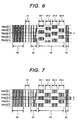
- the system uses a servo pattern as shown in Fig. 6.
- the pattern can be observed by thinly applying a magnetic fluid on the surface of the recording medium and using a magnetic field microscope.
- the servo pattern has a zone 40 for adjusting a reproduction signal output and a marker zone 41, a gray code zone 42 having information such as an address code, and a servo burst zone 43, and a code 44 indicative of the end of a servo zone.
- five information tracks are shown.
- pattern groups 43-1, 43-2, 43-3, and 43-4 which are deviated by 1/2 or 1/n (n: real number) of the track width (or track pitch) in the servo burst zone.
- n real number
- a signal waveform shown in Fig. 8 is obtained.
- the amplitude depends on the distance between each pattern group and the center of the reproduction part. That is, since the pattern group 43-2 is positioned further than the pattern group 43-1 to the center of the reproduction part, the amplitude of a signal from the pattern group 43-2 is smaller. The amplitude of a signal from the pattern group 43-3 to which the reproduction part approaches the most is the largest.
- the central position of the reproduction part can be calculated from the signal.
- the magnetic head By transmitting a control signal to the actuator so as to maintain the calculated position, the magnetic head can be positioned over a predetermined information track (held at a predetermined radial position).
- various servo patterns are written onto the surface of a medium by an apparatus called a servo track writer upon assembly of the magnetic recording apparatus. After that, the casing is sealed in order to prevent invasion of dusts upon the apparatus, so that the servo track cannot be rewritten after shipment of the apparatus.
- the performance of a storage is determined by the speed of input/output operations and a storage capacity. In order to enhance the competitiveness of a product, it is indispensable to shorten the access time and increase the capacity. In recent years, the size of the storage is being reduced in response to a request of reducing the size and weight of each information device in general. In order to satisfy the requests, a magnetic storage which can write a large amount of magnetic information to a single recording medium and reproduce the information has to be developed.
- the capacity of an information device will be further increased and a device in the 10 Gb/in 2 class will appear in the near future. It is considered that the density in the recording direction can be improved by developing a write magnetic pole material having a high resistivity or increasing a write frequency. As for the increase in the density in the cross-track direction, however, even if the geometrical width of the write magnetic pole or the recording part, since there is a problem in the positioning accuracy of the magnetic head, it is considered to be difficult to improve the density.
- the conventional servo burst pattern 43 constructing a servo pattern has to be written in a position deviated with respect to the information track (position deviated by 1/2 or 2/3 of the track pitch).
- the recording apparatus is attached to a dedicated device called a servo track writer.
- the servo track writer successively writes patterns by controlling the head position of the recording device.
- the head position is controlled by extending an arm from the servo track writer to the recording apparatus.
- the casing of the magnetic recording apparatus is closed, the servo pattern cannot be therefore written.
- the life of the whole device is finished at a time when a defect occurs in the information track accompanying degradation in the head or the recording medium which constructs the magnetic recording apparatus.
- the problem causes high initial percent defective.
- an expensive device of over-specification has to be used.
- a magnetic storage which can write a large amount of magnetic information into a single recording medium and reproduce the information.
- a magnetic recording apparatus is provided with a magnetic head having means for writing and reproducing information to/from a magnetic recording medium and a positioning system for the magnetic head.
- the apparatus is newly provided with a function of generating a positioning signal from a difference, a sum, or a ratio of a pulse amplitude on the positive side (hereinbelow, called a positive pulse amplitude) of a reproduction signal and a pulse amplitude on the negative side (hereinbelow, called a negative pulse amplitude) as a means for positioning the magnetic head to a predetermined position when information is outputted/inputted.
- a giant magnetoresistive element is used as means for reproducing the magnetic head.
- a tunneling magnetoresistive element is used as means for reproducing the magnetic head.
- a dual magnetoresistive element constructed by at least two functional films is used as means for reproducing the magnetic head.
- the center of the width of a servo pattern and the center of the width of a data pattern are positioned on tracks on the same circumference.
- a fluctuation of the center position of the servo pattern existing in the same information track is within 10% of an information track pitch.
- the zone of the servo pattern can be narrowed and a recording apparatus in which the ratio of a data zone is increased to 95% or higher is realized.
- two peak hold circuits for processing the positive pulse signal and the negative pulse signal included in the reproduction signal from the magnetic head, respectively, and a subtracter, an adder, and a divider for calculating outputs from the two peak hold circuits are provided in the magnetic recording apparatus.
- data is written to the recording medium on the basis of information obtained by multiplexing a servo signal onto a data signal.
- a function of extracting a servo signal having an arbitrary frequency from the reproduced signal and calculating the position information from a difference between a positive pulse amplitude and a negative pulse amplitude of the servo signal is provided.
- frequencies of servo signals extracted from the reproduction signals are made different in neighboring information tracks.
- a band-pass filter is used to extract the servo signal from the reproduced signal.
- the difference between the frequencies of the servo signals from the neighboring information tracks is wider than the band width of the band-pass filter.
- the center frequency of the band-pass filter is made variable.
- an amplifier for correcting the positive pulse amplitude and the negative pulse amplitude, respectively, on the basis of the output of the comparator is provided in the magnetic recording apparatus.
- a circuit for decoding the signal of the data zone is provided at the post stage of the amplifier.
- a servo signal for positioning is allowed to be generated by the user or the apparatus itself upon manufacture of the magnetic recording apparatus.
- the process has to be carried out in a state where at least one recording track serving as a reference has been preliminarily written.
- a conventional servo track writer can be used for writing the reference track. Since the writing zone is narrow, an influence exerted by the writing operation on the throughput is extremely small.
- the center of a reproduction track is apart from the center of a write track by the half or more of the width of the write track with respect to the positional relation between a functional element constructing the means for reproducing the servo signal and a functional element constructing the means for recording the servo signal.
- a giant magnetoresistive element is used as means for reproducing the magnetic head.
- a tunneling magnetoresistive element is used as another reproducing means.
- a dual magnetoresistive element constructed by at least two functional films is used.
- the center of the width of a servo pattern and the center of the width of a data pattern are positioned on tracks on the same circumference.
- two peak hold circuits and a comparator for detecting the difference between outputs from the two peak hold circuits are provided in the magnetic recording apparatus.
- the deviation amount of the central position of the servo pattern existing in the same information tracks is set within 10% of the information track pitch.
- At least two peak hold circuits for separately processing the positive pulse signal and the negative pulse signal included in the reproduction signal from the magnetic head and a comparator for detecting a difference between outputs form the two peak hold circuit are provided.
- a function of formatting the information track by using the reference track for positioning as a starting point by a signal sent through an interface circuit of the magnetic recording apparatus is provided.
- FIG. 1 shows a conceptual diagram showing an electric circuit construction of a magnetic recording apparatus. Magnetic information is written in the recording medium 11.
- the magnetic head 12 has the function of converting the magnetic information from the recording medium to an electric signal.
- the magnetic head 12 is moved by the rotary actuator 13 and the position of the magnetic head 12 is held.
- a control current is flowed from a driver 14 for positioning to the rotary actuator 13.
- the driver 14 for positioning is driven by a signal from a magnetic disk controller 15.
- the magnetic disk controller 15 information from an external apparatus 16 is processed and arithmetic operations and the like are executed.
- the arithmetic operation includes at least the function of calculating the position of the magnetic head on the basis of a signal from the servo pattern, obtaining the difference between the position and a target position, and calculating a distance (the angle of rotation of the rotary actuator) for moving the magnetic head from the difference.
- the electric signal generated by using the servo pattern is sent from the magnetic head 12 to two peak hold circuits 18 and 19 via an automatic amplification controller 17 called an AGC.
- Each of the circuits 18 and 19 comprises at least a resistor, a capacitor, and a diode as shown in the lower part of Fig. 1.
- the difference between the two peak hold circuits 18 and 19 is that the directions of the diodes are different. Because of the difference, a positive pulse signal and a negative pulse signal are separated.
- the resistor and the capacitor integrate signals which have passed the diode in a predetermined time and detect the amplitude (peak) of the signal.
- the starting point of the integration is controlled by a signal from the magnetic disk controller 15. Since the specific method is similar to that of the conventional technique, its description is omitted here. Although it is similarly necessary to reset charges accumulated in the capacitor, the method is also similar to that of the conventional technique so that the description is omitted here.
- the peak hold circuits have the function of separately detecting the positive and negative pulse amplitudes included in a signal from the servo pattern.
- the detected amplitude information is sent to a computing unit 35 at the post stage where the calculation of subtraction, addition, or comparison is executed to the positive and negative pulse amplitudes.
- An output from the computing unit 35 is sent to the magnetic disk controller 15. The movement amount of the magnetic head is calculated from the signal.
- the following arithmetic operation is executed by the computing unit 35.
- the off-track value is set to Ph, it is obtained as follows by using a positive pulse amplitude Vp and a negative pulse amplitude Vm of a reproduction signal. Ph ⁇ (Vp - Vm)/(Vp + Vm)
- the computing unit 35 comprises at least two operational amplifiers, resistors, dividers, and the like as shown in the lower part of the diagram.
- the upper operational amplifier has the function of obtaining the sum of two signals and the lower operational amplifier has the function of obtaining the difference between two signals.
- the off-track value can be obtained from the expression (1) calculated by the computing unit 35.
- Similar position information can be also obtained from the ratio of the positive and negative pulse amplitudes of a reproduction signal.
- a divider is used in the computing unit 35. That is, when the off-track value is set to Ph, it is calculated as follows by using the positive pulse amplitude Vp and the negative pulse amplitude Vm of a reproduction signal. Ph ⁇ Vp/Vm
- the position information can be also obtained from the difference between the positive pulse amplitude and the negative pulse amplitude of a reproduction signal.
- a subtracter is used in the computing unit 35. That is, when the off-track value is set to Ph, it is calculated as follows by using the positive pulse amplitude Vp and the negative pulse amplitude Vm of the reproduction signal. Ph ⁇ Vp - Vm
- a giant magnetoresistive element is used as reproduction means of the magnetic head. According to our examination, it was confirmed that a tunneling magnetoresistive element and a dual magnetoresistive element comprising at least two functional films are reproduction means have similar functions. A case where either one of the elements is employed as the reproduction part of the magnetic head can be applied to the invention by the reason which will be described hereinlater.
- the output of the AGC 17 is also sent to an active amplifier 31.
- An output of the active amplifier 31 is sent to a signal process circuit 34 and is sent to the magnetic disk controller 15.
- the active amplifier 31 has the function of amplifying the positive and negative pulse amplitudes of the reproduction signal with respective gains on the basis of information from the magnetic disk controller 15.
- the information from the magnetic disk controller 15 is used as means for correcting the difference between the positive pulse amplitude and the negative pulse amplitude. Consequently, the gains of the positive and negative pulse amplitudes are adjusted by the active amplifier 31 on the basis of the output of the computing unit and the adjusted amplitudes are sent to the post stage, thereby making the positive and negative pulse amplitudes to be almost equal.
- Information to be recorded in the signal from the magnetic disk controller 15 is transmitted via a write precompensation and precoding circuit 33 and a write driver 32 to the magnetic head.
- the construction of a part related to the writing operation is similar to that in the conventional magnetic recording apparatus.
- Fig. 2 shows a circuit construction of a conventional magnetic recording apparatus. According to the construction, the existence of the recording medium 11, magnetic head 12, rotary actuator 13, positioning driver 14, magnetic disk controller 15, write precompensation and precoding circuit 33, and write driver 32 is the same as Fig. 1.
- the different points are that there is one peak hold circuit 118 and that the active amplifier 31 does not exist at the front stage of the signal processing circuit.
- the reason why only one peak hold circuit 118 is used is that the positive and negative pulse amplitudes of the reproduction signal are processed without being discriminated. The process has been already described with reference to Fig. 8. Since the positive and negative pulse amplitudes are processed without being discriminated, it is naturally unnecessary to provide the active amplifier 31 at the front stage of the signal processing circuit.
- Fig. 3 shows the result (in which polarities are omitted and only amplitude values are shown) of measurement of changes in the positive pulse amplitude Vp and the negative pulse amplitude Vm of a signal detected when the magnetic head using the giant magnetoresistive element as a reproduction part is moved (offset) in the track width direction from the center of the information track. From the chart, it is understood that the positive pulse amplitude becomes larger than the negative pulse amplitude on the negative offset side. On the contrary, it is understood that negative pulse amplitude becomes larger than the positive pulse amplitude on the positive offset side.
- a similar characteristic curve can be also obtained by calculating (Vp - Vm). The result is also shown by a broken line in Fig. 3. In this case, it is understood that the value decreases monotonously in a rather narrow range with respect to the offset amount. A positioning operation similar to the above can be therefore realized in a rather narrow range with respect to the positional deviation amount of the magnetic head.
- the giant magnetoresistive element used in the embodiment is constructed by sequentially depositing a base film (Hf: 5 nm), an antiferromagnetic film (Fe-Mn; 10 nm), a magnetic film (first ferromagnetic film: NiFe alloy film: 6 nm), a non-magnetic film (Cu: 3nm), a soft magnetic film (second ferromagnetic film: NiFe alloy film: 6nm) having the function of a free magnetizing direction layer, and a protective film (Hf: 5 nm).
- the construction has the construction of a spin valve element structure which is a kind of the giant magnetoresistive element in a wide sense. It was confirmed that a difference occurs between the positive and negative pulse amplitudes by an offset of the magnetic head as long as the spin valve element construction is used.
- a value which can be obtained from the positive and negative pulse amplitudes is equal to an output of the comparator 35 shown in Fig. 1. From the output, the positional relation between the single information track and the magnetic head can be led. The position information similar to the amplitude difference obtained from the signal from the servo burst patterns which are deviated by the 1/2 or 2/3 of the track width is derived. The information track position to which the magnetic head comes closest is read from the gray code zone and the detailed position information is calculated from the ratio of the positive pulse amplitude to the negative pulse amplitude, thereby enabling the magnetic head to be positioned in a manner similar to the conventional positioning.
- a change occurs in the positive and negative pulse amplitudes when the reproduction part left from the center of the information track.
- the servo burst pattern can be therefore arranged on the information tracks. Such a state is shown in Fig. 7. In Fig. 7, five servo tracks are shown.
- the servo patterns have a signal gain control zone 40, a marker zone 41, a gray code zone 42 having information such as address code, and a code 44 indicative of the end of the servo zone.
- the center of a servo burst pattern group 43 coincides with the center of the track.
- the neighboring servo burst patterns are alternately arranged. The arrangement has the effect of preventing an erroneous operation for reading the next servo burst pattern when an off-track amount is large.
- reproduction signals (46-1, 46-3) as shown in Fig.9a are obtained from burst pattern groups 43-1 and 43-3.
- reproduction signals (46-1 and 46-3) shown in Fig. 9b are obtained from the burst pattern groups 43-1 and 43-3.
- the lines ⁇ and ⁇ are positioned apart from each other toward the opposite ends from the center of the information track and are "off-tracked" in the opposite directions. In such a case, as it is clear from the measurement result shown in Fig. 3, it is understood that the positive pulse amplitude and the negative pulse amplitude of a signal are different and the magnitudes of the amplitudes are reversed.
- the example using two burst pattern groups has been described.
- the servo zone can be narrowed from this effect. Specifically, the ratio of the servo zone to the other zone can be reduced to 5% or smaller.
- 30 bits are necessary for a reproduction signal gain control zone, likewise, 12 bits for the gray pattern (gray zone), 4 bits for a servo mark (marker zone), 32 bits for the burst pattern, and 2 bits for the end mark are necessary.
- 32 bits of the burst pattern can be shortened up to 8 bits. From the effect, the servo zone can be set to 5% or smaller and the data zone can be set to 95% or larger.
- a signal of a low frequency equal to the burst pattern can be also multiplexed on the data signal. Extraction of the servo signal having the low frequency can be realized by a band-pass filter. In the process, however, there is the possibility that a servo signal from the neighboring track is erroneously reproduced in a state of off-track. In order to prevent this, the frequency of the servo signal extracted from the reproduction signal is made different from that in the neighboring information track. For the purpose of reproducing the signals distinctively, the difference between the frequencies of the servo signals from the neighboring information tracks is made wider than the band width of the band-pass filter or the central frequency of the band-pass filter is made variable.
- Those circuit can be realized by inserting the above band-pass filter to the post stage of the AGC 17 shown in Fig. 1.
- the band-pass filter changes the central frequency by the signal from the magnetic disk controller 15. Those functions can be easily realized by applying the existing electric circuit technique.
- the position information can be generated from the result.
- the important point of the function is that the position information can be detected in a state where the center of the servo burst pattern coincides with the center of the information track (the center in the width direction of the servo pattern and the center of the width of the data pattern are positioned on the same circumference.
- a deviation of the central position of the servo patterns existing on tracks on the same circumference is within 10 percent of the track pitch since the servo patterns do not have to be successively written.
- a signal suitable for generating the positioning signal is obtained from any of the giant magnetoresistive element, the tunneling magnetoresistive element, and the dual magnetoresistive element constructed by at least two functional films.
- Each of the elements has a soft magnetic film whose magnetization state changes by the magnetic field from the recording medium.
- the magnetization of the soft magnetic layer is oriented in the track width direction.
- the sensitivity distribution is of a Gaussian type in which the center of the track is a symmetry axis. The sensitivity distribution is obtained from the sum of the positive and negative pulse amplitudes. Consequently, although the off-track state can be detected from the sum of the positive and negative pulse amplitudes, the off-track direction cannot be known.
- Figs.5a to 5e are conceptual diagrams of a spin valve type element as a giant magnetoresistive element. A change in resistance of a film occurs in such a manner that a magnetic field 53 acts as shown by Fig.5a, a magnetization 54 of a soft magnetic rotatable magnetization layer 51 turns, and the angle between the magnetization and the magnetization direction of a spin driving layer 52 changes.
- the magnetic field When the head moves over the element toward the left of the paper from the center of the information track, the magnetic field generates from the end of the information track. That is, a magnetic field 53-1 shown in Fig.b or 53-2 shown in Fig.5c is applied. Whether the magnetic field 53-1 or 53-2 is applied depends on the polarity of the magnetic domain and the magnetic field is repeatedly applied. When the movements of the magnetization 54-1 and 54-2 by the magnetic fields 53-1 and 53-2 are examined, it is considered that the rotation of the magnetization 54-1 whose in-plane magnetic field component is the same is larger than that of the magnetization 54-2.
- magnetic fields 53-3 and 53-4 shown in Fig.5d and Fig.5e are applied at the end of the element on the opposite side.
- the direction of the magnetic field 53-4 is similar to that of the magnetization 54-4, the magnetization easily rotates.
- any of the tunneling magnetoresistive element and the dual magnetoresistive element constructed by at least two functional films since the magnetization of the soft magnetic layer for detecting the magnetic field is oriented in the track width direction, when the magnetic head is moved from the center of the information track, a change occurs in the amplitudes on both of the positive and negative sides by the same effect as above.
- the invention can be applied.
- the characteristic is not suitable for reproducing the recorded information since the recorded information corresponds to signals of both of the positive and negative pulse amplitudes in the magnetic recording apparatus.
- the signal amplitude of one side is reduced by approximately 20%, it causes an erroneous operation.
- the magnetic head positioning accuracy has to be increased extremely.
- the technique uses the fact that the difference between the positive and negative pulse amplitudes is known from the difference between the signal amplitudes from the servo burst patterns. Since the difference in neighboring data patterns can be considered to be almost constant, the amplification factor of the positive and negative pulse amplitudes is changed by using the value, thereby enabling the amplitude to be equal to the amplitude in an almost "on-track" state at the post stage.
- the amplifier 31 for correcting the positive and negative pulse amplitudes on the basis of the output of the comparator 35 shown in Fig. 1 is provided in the magnetic recording apparatus and the signal processing system 34 is arranged at the post stage.
- JP-A Japanese Patent Application
- JP-A-8-212733 the difference between the positive and negative pulse amplitudes is not considered. Consequently, means for increasing the gain of a positioning loop for the purpose of maintaining the stability against a mechanical external disturbance is required. According to our additional examination, it is necessary to separately prepare a circuit for forming the servo pattern.
- a special magnetic head shown in Fig. 11 is used in the present invention.
- the magnetic head has the construction such that the track center of a reproduction part 23 is apart from the track center of a write magnetic pole 27 by the half of the track width or more (when this magnetic head is compared with the conventional magnetic head shown in Fig. 10, it is understood that the reproduction part is deviated to the right side).
- the meaning of the half of the track width is as follows. An overlap amount of the reproduction part and the neighboring track used for generating the positioning signal when the magnetic head is off-tracked increases. When the overlap amount increases, as obviously understood from the characteristics shown in Fig. 3, the signal amplitude changes in a state where the linearity is kept the most and a highly accurate positioning signal can be obtained. It does not correspond to the offset for the yaw angle seen in the conventional head. Consequently, in order to execute the invention strictly, it is necessary to calculate a deviation between the reproduction part and the write zone, in consideration of the linearity of the head output change and the yaw angle. The calculation is easily understood by a person skilled in the art.
- the giant magnetoresistive element, tunneling magnetoresistive element, or the dual magnetoresistive element constructed by at least two functional thin films is used as a reproducing means.
- the center of the width of the servo pattern coincides with the center of the width of the data pattern.
- Figs.12a to 12c show a method of self-generating servo patterns.
- Fig.12a shows a state where one servo pattern 63 (at least, the servo burst pattern is included) is written on the innermost or outermost circumference.
- the center of a write head 61 and the center of the servo pattern 63 coincide with each other.
- the center of the reproduction part is away from the track center of the write zone by the half of the track width, the center of the reproduction part 62 is deviated by about 1/2 of the width of the servo pattern.
- a neighboring servo pattern 64 is written. For the positioning in this case, position information from the servo pattern 63 which has been written first is used.
- servo patterns can be formed on the entire face of the magnetic recording medium. It will be easily understood that, in order to realize the process, it is necessary to have two peak hold circuits for respectively processing positive pulse signal and a negative pulse signal included in a reproduction signal from the magnetic head and a comparator for detecting the difference between outputs of the two peak hold circuits within the magnetic recording apparatus.
- At least one reference track for positioning has to be provided on the face of a recording medium.
- a servo track writer can be used for positioning the reference track or, simply, the rotation of a rotary actuator can be mechanically regulated (damped) only at the innermost or outermost circumferencial part.
- a plurality of the reference tracks for positioning can exist in the radial direction of a recording medium.
- formatting of an information track by using the reference track for positioning as a starting point is executed by a signal sent via an interface circuit of the magnetic recording apparatus. It can be executed either at the stage of shipping from a factory or at a stage where a defect occurs in an arbitrary address position in the medium as a result of employment of the magnetic recording apparatus by the user since the formatting in the apparatus of the invention can be executed in a state where the casing of the apparatus is closed.
- the conventional apparatuses do not have this function.
- the function is created by the present invention.
- a function of detecting the position of a defect in a medium and executing a registering process in connection with the formatting process is provided.
- the function is important in order to assure the reliability similar to that of a conventional apparatus.
- it is efficient to execute the formatting through a magnetic disk controller and this arrangement is employed in the embodiment.
- a sequence of the execution of the formatting is preliminarily programmed in the magnetic disk controller.
- a function of arbitrary changing the format pitch to format the information track by avoiding a defect is also provided. This can be realized by varying the track pitch feed amount at any time.
- the servo patterns can be formed on the whole face of a magnetic recording medium and the formatting process for the whole face of a medium by the servo track writer is made unnecessary. Consequently, the throughput of the apparatus limited by the servo track writer can be increased more than ten times and the price of the magnetic recording apparatus can be accordingly reduced by about 10%.
- the magnetic head can be accurately positioned by the realization of highly precise servo patterns having a small amount of noise signals and the high density magnetic storage can be obtained.
Landscapes
- Engineering & Computer Science (AREA)
- Chemical & Material Sciences (AREA)
- Nanotechnology (AREA)
- Crystallography & Structural Chemistry (AREA)
- Signal Processing (AREA)
- Manufacturing & Machinery (AREA)
- Physics & Mathematics (AREA)
- Mathematical Physics (AREA)
- Theoretical Computer Science (AREA)
- Moving Of The Head To Find And Align With The Track (AREA)
- Adjustment Of The Magnetic Head Position Track Following On Tapes (AREA)
- Magnetic Heads (AREA)
Applications Claiming Priority (3)
| Application Number | Priority Date | Filing Date | Title |
|---|---|---|---|
| JP316813/97 | 1997-11-18 | ||
| JP31681397 | 1997-11-18 | ||
| JP9316813A JPH11149730A (ja) | 1997-11-18 | 1997-11-18 | 磁気記録装置 |
Publications (2)
| Publication Number | Publication Date |
|---|---|
| EP0917134A2 true EP0917134A2 (fr) | 1999-05-19 |
| EP0917134A3 EP0917134A3 (fr) | 2000-09-13 |
Family
ID=18081212
Family Applications (1)
| Application Number | Title | Priority Date | Filing Date |
|---|---|---|---|
| EP98121193A Withdrawn EP0917134A3 (fr) | 1997-11-18 | 1998-11-13 | Appareil pour l'enregistrement magnétique |
Country Status (3)
| Country | Link |
|---|---|
| EP (1) | EP0917134A3 (fr) |
| JP (1) | JPH11149730A (fr) |
| KR (1) | KR19990045308A (fr) |
Cited By (1)
| Publication number | Priority date | Publication date | Assignee | Title |
|---|---|---|---|---|
| EP1134729A3 (fr) * | 2000-03-14 | 2002-08-07 | Kabushiki Kaisha Toshiba | Tête magnétique et système d' enregistrement et de reproduction magnétique |
Families Citing this family (2)
| Publication number | Priority date | Publication date | Assignee | Title |
|---|---|---|---|---|
| US6791775B2 (en) * | 2001-10-15 | 2004-09-14 | Samsung Electronics, Co., Inc. | Method and apparatus to distinguish effects of adjacent track encroachment from head thermal movement |
| KR100691109B1 (ko) | 2005-07-12 | 2007-03-09 | 엘지전자 주식회사 | 고밀도 광디스크에서 데이터 서치 방법 |
Family Cites Families (9)
| Publication number | Priority date | Publication date | Assignee | Title |
|---|---|---|---|---|
| JPS61910A (ja) * | 1984-06-14 | 1986-01-06 | Nippon Telegr & Teleph Corp <Ntt> | 位置情報検出信号発生方法 |
| JPS6398819A (ja) * | 1986-10-14 | 1988-04-30 | Nippon Telegr & Teleph Corp <Ntt> | 位置信号発生方法 |
| JPH0194574A (ja) * | 1987-10-06 | 1989-04-13 | Y E Data Inc | 磁気記録装置のサーボデータの記録方式 |
| JP2551043B2 (ja) * | 1987-10-31 | 1996-11-06 | ソニー株式会社 | トラッキング制御装置 |
| JP2531814B2 (ja) * | 1989-01-27 | 1996-09-04 | インターナシヨナル・ビジネス・マシーンズ・コーポレーシヨン | サ―ボ制御システム及び固定磁気ディスク駆動装置 |
| JPH0388113A (ja) * | 1989-08-31 | 1991-04-12 | Nec Corp | ベリードサーボ方式用サーボ情報検出装置 |
| US5485322A (en) * | 1993-03-08 | 1996-01-16 | International Business Machines Corporation | Method and system for writing a clock track on a storage medium |
| JPH07211028A (ja) * | 1994-01-10 | 1995-08-11 | Sony Corp | ヘッド装置およびそれを使用するための基準トラックの形成方法 |
| US5612833A (en) * | 1994-12-02 | 1997-03-18 | International Business Machines Corporation | Radial self-propagation pattern generation for disk file servowriting |
-
1997
- 1997-11-18 JP JP9316813A patent/JPH11149730A/ja active Pending
-
1998
- 1998-11-13 EP EP98121193A patent/EP0917134A3/fr not_active Withdrawn
- 1998-11-16 KR KR1019980049017A patent/KR19990045308A/ko not_active Abandoned
Cited By (2)
| Publication number | Priority date | Publication date | Assignee | Title |
|---|---|---|---|---|
| EP1134729A3 (fr) * | 2000-03-14 | 2002-08-07 | Kabushiki Kaisha Toshiba | Tête magnétique et système d' enregistrement et de reproduction magnétique |
| US6636390B2 (en) | 2000-03-14 | 2003-10-21 | Kabushiki Kaisha Toshiba | Magnetic head and magnetic recording and reproducing system |
Also Published As
| Publication number | Publication date |
|---|---|
| KR19990045308A (ko) | 1999-06-25 |
| EP0917134A3 (fr) | 2000-09-13 |
| JPH11149730A (ja) | 1999-06-02 |
Similar Documents
| Publication | Publication Date | Title |
|---|---|---|
| US6157510A (en) | Magnetic storage device with multiple read elements which are offset laterally and longitudinally | |
| US5995309A (en) | Magnetic recording medium | |
| KR100259429B1 (ko) | 강화된 자기저항을 갖는 스핀 밸브 센서 | |
| US6999257B2 (en) | Magnetic disk drive with structure for avoiding DC magnetic disturbance on a disk surface | |
| US7106549B2 (en) | Magnetic recording and reproducing apparatus and magnetic recording medium | |
| US20070242383A1 (en) | Method and Apparatus for Improving Signal-to-Noise Ratio for Hard Disk Drives | |
| JPH07153043A (ja) | 磁気ヘッド位置の検知方法およびその装置 | |
| JP2004509428A (ja) | 側面シールドを用いた高面積密度のリーダ用の新しいmr構造体 | |
| US7193807B1 (en) | Method and apparatus for reducing effective track width through highly skewed head angles | |
| US7969691B2 (en) | Magnetic head and magnetic disk system having a read sensor and a sensing current | |
| JPH03259471A (ja) | トラック追従制御装置 | |
| US6873482B1 (en) | Magnetic recording drive with continuous magnetic servo system | |
| US5615063A (en) | Magnetoresistive head bias current switching based on skew angle | |
| US7787208B2 (en) | Bit patterned medium having super-track, method of tracking track of bit patterned medium, head appropriate for bit patterned medium, and information recording/reproducing apparatus including bit patterned medium head | |
| US5555142A (en) | Magnetic disk system | |
| US7317596B2 (en) | Magnetic recording disk drive having read head with high cross-track resolution and disk with low bit-aspect-ratio | |
| KR100425575B1 (ko) | 자기기록장치, 자기헤드의 조절방법, 및 자기기록매체 | |
| EP0645764B1 (fr) | Méthode et appareil pour le positionnement avec asservissement de phase modulée dans une unité de stockage à accès direct | |
| EP0917134A2 (fr) | Appareil pour l'enregistrement magnétique | |
| US6128149A (en) | Method and system for detecting common mode disturbances from a dual stripe magnetoresistive head | |
| US6600636B1 (en) | Magnetic head with write element offset from read element | |
| US7532429B2 (en) | Write-head positioning method and disk drive | |
| US6091566A (en) | Magnetoresistive head and hard drive system having offsets from center of the servo area to minimize microjogging | |
| US6999259B2 (en) | Master disc and method of manufacturing the same | |
| JPH0973620A (ja) | 磁気記録再生装置 |
Legal Events
| Date | Code | Title | Description |
|---|---|---|---|
| PUAI | Public reference made under article 153(3) epc to a published international application that has entered the european phase |
Free format text: ORIGINAL CODE: 0009012 |
|
| AK | Designated contracting states |
Kind code of ref document: A2 Designated state(s): AT BE CH CY DE DK ES FI FR GB GR IE IT LI LU MC NL PT SE |
|
| AX | Request for extension of the european patent |
Free format text: AL;LT;LV;MK;RO;SI |
|
| PUAL | Search report despatched |
Free format text: ORIGINAL CODE: 0009013 |
|
| AK | Designated contracting states |
Kind code of ref document: A3 Designated state(s): AT BE CH CY DE DK ES FI FR GB GR IE IT LI LU MC NL PT SE |
|
| AX | Request for extension of the european patent |
Free format text: AL;LT;LV;MK;RO;SI |
|
| AKX | Designation fees paid | ||
| REG | Reference to a national code |
Ref country code: DE Ref legal event code: 8566 |
|
| STAA | Information on the status of an ep patent application or granted ep patent |
Free format text: STATUS: THE APPLICATION IS DEEMED TO BE WITHDRAWN |
|
| 18D | Application deemed to be withdrawn |
Effective date: 20010601 |