EP0917157A2 - Isolateur - Google Patents
Isolateur Download PDFInfo
- Publication number
- EP0917157A2 EP0917157A2 EP98660120A EP98660120A EP0917157A2 EP 0917157 A2 EP0917157 A2 EP 0917157A2 EP 98660120 A EP98660120 A EP 98660120A EP 98660120 A EP98660120 A EP 98660120A EP 0917157 A2 EP0917157 A2 EP 0917157A2
- Authority
- EP
- European Patent Office
- Prior art keywords
- insulator
- primary conductor
- measuring element
- disposed
- voltage measuring
- Prior art date
- Legal status (The legal status is an assumption and is not a legal conclusion. Google has not performed a legal analysis and makes no representation as to the accuracy of the status listed.)
- Granted
Links
Images

Classifications
-
- H—ELECTRICITY
- H01—ELECTRIC ELEMENTS
- H01B—CABLES; CONDUCTORS; INSULATORS; SELECTION OF MATERIALS FOR THEIR CONDUCTIVE, INSULATING OR DIELECTRIC PROPERTIES
- H01B17/00—Insulators or insulating bodies characterised by their form
- H01B17/005—Insulators structurally associated with built-in electrical equipment
-
- G—PHYSICS
- G01—MEASURING; TESTING
- G01R—MEASURING ELECTRIC VARIABLES; MEASURING MAGNETIC VARIABLES
- G01R15/00—Details of measuring arrangements of the types provided for in groups G01R17/00 - G01R29/00, G01R33/00 - G01R33/26 or G01R35/00
- G01R15/14—Adaptations providing voltage or current isolation, e.g. for high-voltage or high-current networks
- G01R15/16—Adaptations providing voltage or current isolation, e.g. for high-voltage or high-current networks using capacitive devices
-
- G—PHYSICS
- G01—MEASURING; TESTING
- G01R—MEASURING ELECTRIC VARIABLES; MEASURING MAGNETIC VARIABLES
- G01R15/00—Details of measuring arrangements of the types provided for in groups G01R17/00 - G01R29/00, G01R33/00 - G01R33/26 or G01R35/00
- G01R15/14—Adaptations providing voltage or current isolation, e.g. for high-voltage or high-current networks
- G01R15/18—Adaptations providing voltage or current isolation, e.g. for high-voltage or high-current networks using inductive devices, e.g. transformers
- G01R15/181—Adaptations providing voltage or current isolation, e.g. for high-voltage or high-current networks using inductive devices, e.g. transformers using coils without a magnetic core, e.g. Rogowski coils
Definitions
- the present invention relates to an insulator, particularly a bushing insulator comprising a primary conductor, centrally led through the body of the insulator, at least one of its ends having given external dimensions, a current measuring element disposed about the primary conductor, and at least one voltage measuring element based on voltage division and also disposed about the primary conductor.
- the external dimensions of an insulator usually have to be increased when current and voltage measuring sensors are disposed inside the insulator. This is because both the current measuring sensor and the voltage measuring sensor are typically disposed axially with respect to one another with the primary conductor passing coaxially through them.
- the external dimensions of the insulator have to be increased both in the diametrical and in the longitudinal direction of the insulator to be able also to arrange sufficient amounts of insulating material around these sensors.
- an insulator particularly a bushing insulator, in which the above problems are solved, i.e. an insulator provided with current and voltage measuring sensors and with external dimensions, which, however, correspond to conventional insulators which do not comprise such sensors.
- a primary solution to the above problem is provided by the arrangement of the invention, characterized in that the external dimensions of the primary conductor, at least by the voltage measuring element, define a substantially, e.g. at least 5%, smaller cross-sectional area than the cross-sectional area defined by the external dimensions of the primary conductor at said end thereof.
- the main idea of the insulator of the invention is that at some point between the ends the diameter of the copper bar used as the primary conductor can be significantly reduced e.g. by lathe work, provided that every point in cross-sectional area of the rail remains such that the overall heating allowed for the primary conductor is not exceeded in any normal use.
- the end of the primary conductor is typically connected to the busbar by a pin from the threaded hole at the end of the conductor.
- the area of the joint surface of the primary conductor is defined by the difference between the outer diameter of the primary conductor and the threaded hole provided therein, further reduced by small facets on the side of both the threaded hole and the outer edge of the primary conductor.
- the distance between the primary conductor and the voltage measuring sensor is 10 mm in e.g. 24 kV bushing insulators.
- a smaller primary conductor diameter is immediately reflected as an identical decrease in the diameter of the voltage measuring sensor, which, in turn, is reflected in the outer diameter of the insulator.
- the insulator further comprises, for voltage identification, a second voltage measuring element displaced substantially axially to said voltage measuring element
- the external dimensions of the primary conductor by said second voltage measuring element also define a substantially, e.g. at least 5%, smaller cross-sectional area than the cross-sectional area defined by the external dimensions of the primary conductor at said end thereof.
- the reduced portion of the primary conductor thus preferably covers the area of all current and voltage measuring sensors to allow a smaller outer diameter of the insulator by all sensors.
- the axial length of the insulator can, in turn, be shortened by disposing the current measuring element concentrically about the voltage measuring element.
- US Patent 4,709,205 discloses a principle according to which a Rogowski sensor can be built of separate coils, coiled about straight bobbins in the usual manner instead of toroidal coiling.
- the coils are arranged about the primary conductor, fastened to a printed board and series coupled electrically. Although the cross-sectional area of the innermost turns is small, enough turns can yet be arranged in the coil to ensure a sufficient output signal.
- the above solution allows a Rogowski sensor in the insulator of the invention to be formed from a plurality of cylindrical coils, whereby the lengths and diameters of individual coils can be kept minimal.
- the nested arrangement of the sensors according to the solution of the invention provides a short bushing insulator.
- the insulator of the invention is further characterized in that the coils of said Rogowski sensor are disposed in a casing of a conductive material, comprising two halves, joined together without their cross-section forming a closed loop.
- the casing protects the sensor against effects of external electric fields, and on the other hand the sensor coils can bear against the casing so that the coils can be disposed at exactly even distances at the periphery of a circle and made to remain in place until the entire sensor has been cast in resin.
- the diameter of the primary conductor can be freely reduced, and the diameters of the sensors disposed about it can be made correspondingly so small that the outer diameter of the entire insulator remains equal to that of the insulator in which the entire length of the primary conductor has the same diameter and the insulator is not provided with current or voltage measuring sensors. If, contrary to the described embodiment, the primary conductor is widened right after the end of the primary conductor and the joint cross-section formed therein, i.e. in the case of a round primary conductor its diameter is increased, the reduced portion may even be smaller than the diameter corresponding to said joint cross-section.
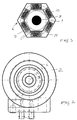
- a coiling 6 of the Rogowski sensor used as the current measuring sensor, is disposed concentrically about the voltage measuring cylinder 7.
- the detailed structure of said coiling is shown in Figure 3.
- said current measuring sensor is formed from a plurality of cylindrical coils 10, coiled on separate bobbins 9 and disposed in the same plane, perpendicular to the axial direction of the insulator, in the shape of a polygon and with their coils coupled in series.
- the operating principle of such a Rogowski sensor has been described above and is also disclosed in said US Patent 4,709,205 and in French Patent 2507811. The operating principle of the sensor is therefore not described in any greater detail herein.
- the Rogowski sensor 6 comprises six coils 10 arranged in the shape of a hexagon.
- the coils 10 constituting the Rogowski sensor are disposed in a protective casing 11 made of thin aluminium to attenuate interference caused by external electric fields.
- This protective casing 11 is preferably built of two halves and shaped so that the coils 10 are disposed at exactly even distances at the periphery of a circle and remain in place until the entire sensor has been cast in resin.
- the halves of the protective casing 11 are so designed that the cross-section of the casing is not a closed loop. This would inhibit the operation of the sensor since the field would not be able to enter the sensor and generate in the sensor coils the voltage required in current measurement.
- a very compact size is an advantage of the insulator of the invention, and, as mentioned above, the size of the bushing insulator of the invention, provided with sensors, can be the same as that of a conventional bushing insulator with no sensors. This makes it possible to replace an installed conventional bushing insulator with the bushing insulator of the invention, provided with sensors, if required. Small size and light weight also cause savings in manufacturing and freight costs. Furthermore, the structure of the Rogowski sensor is advantageous in manufacture compared with conventional toroidal coiling.
- the only drawback in the bushing insulator of the invention is one extra stage of operation in the processing of the copper bar constituting the primary conductor. However, the extra stage can be easily combined with the boring of the threaded holes in the rail.
- the positioning of the coils of the Rogowski sensor employed in the insulator of the invention is important e.g. to minimize the error caused by adjacent phases in the measurement result.
- the Rogowski sensor coils can also be positioned by placing in the aluminium casing a fitting piece cast of plastic, by means of which the coils are disposed at even distances.
Landscapes
- Transformers For Measuring Instruments (AREA)
- Insulators (AREA)
Applications Claiming Priority (2)
| Application Number | Priority Date | Filing Date | Title |
|---|---|---|---|
| FI974212 | 1997-11-12 | ||
| FI974212A FI974212L (fi) | 1997-11-12 | 1997-11-12 | Eristin |
Publications (3)
| Publication Number | Publication Date |
|---|---|
| EP0917157A2 true EP0917157A2 (fr) | 1999-05-19 |
| EP0917157A3 EP0917157A3 (fr) | 2000-06-21 |
| EP0917157B1 EP0917157B1 (fr) | 2005-09-07 |
Family
ID=8549924
Family Applications (1)
| Application Number | Title | Priority Date | Filing Date |
|---|---|---|---|
| EP98660120A Expired - Lifetime EP0917157B1 (fr) | 1997-11-12 | 1998-11-10 | Isolateur |
Country Status (4)
| Country | Link |
|---|---|
| EP (1) | EP0917157B1 (fr) |
| DE (1) | DE69831465T2 (fr) |
| ES (1) | ES2249817T3 (fr) |
| FI (1) | FI974212L (fr) |
Cited By (7)
| Publication number | Priority date | Publication date | Assignee | Title |
|---|---|---|---|---|
| EP1113277A1 (fr) * | 1999-12-29 | 2001-07-04 | ABB T&D Technologies Ltd. | Elément de traversée pour applications de tension moyenne et haute |
| ES2174754A1 (es) * | 2001-03-30 | 2002-11-01 | Gripo Ormazabal S A | Sistema modular de conexion aislada de alta tension con captacion de intensidad y tension. |
| EP1376621A3 (fr) * | 2002-06-28 | 2004-01-28 | ABB Technology AG | Isolateur |
| WO2006134178A1 (fr) * | 2005-06-13 | 2006-12-21 | Ormazabal Protection & Automation, S.L. | Dispositif de commande/de protection pour reseaux de distribution electrique |
| WO2016087685A1 (fr) * | 2014-12-01 | 2016-06-09 | Ormazabal Y Cía, S.L.U. | Adaptateur de traversée pour connexion électrique |
| WO2018108828A1 (fr) | 2016-12-16 | 2018-06-21 | Eaton Industries (Netherlands) B.V. | Combinaison d'un élément conducteur d'électricité, de type manchon, et d'un câble connecteur |
| WO2024006615A1 (fr) * | 2022-06-29 | 2024-01-04 | Siemens Energy Global GmbH & Co. KG | Transformateur d'instrument de faible puissance (lpit) dans un connecteur conique |
Family Cites Families (3)
| Publication number | Priority date | Publication date | Assignee | Title |
|---|---|---|---|---|
| DE2325440A1 (de) * | 1973-05-17 | 1974-11-21 | Siemens Ag | Messwandler mit einer kondensatordurchfuehrung |
| DE4435864C2 (de) * | 1994-10-07 | 1996-07-25 | Pfisterer Elektrotech Karl | Garnitur in Form einer Durchführung oder einer Steckbuchse für Kabelstecker |
| FI965298A7 (fi) * | 1996-12-31 | 1998-07-01 | Abb Transmit Oy | Eristin |
-
1997
- 1997-11-12 FI FI974212A patent/FI974212L/fi not_active Application Discontinuation
-
1998
- 1998-11-10 EP EP98660120A patent/EP0917157B1/fr not_active Expired - Lifetime
- 1998-11-10 ES ES98660120T patent/ES2249817T3/es not_active Expired - Lifetime
- 1998-11-10 DE DE69831465T patent/DE69831465T2/de not_active Expired - Lifetime
Cited By (11)
| Publication number | Priority date | Publication date | Assignee | Title |
|---|---|---|---|---|
| EP1113277A1 (fr) * | 1999-12-29 | 2001-07-04 | ABB T&D Technologies Ltd. | Elément de traversée pour applications de tension moyenne et haute |
| ES2174754A1 (es) * | 2001-03-30 | 2002-11-01 | Gripo Ormazabal S A | Sistema modular de conexion aislada de alta tension con captacion de intensidad y tension. |
| WO2002080308A3 (fr) * | 2001-03-30 | 2002-12-05 | Grupo Ormazabal Sa | Systeme de connexion modulaire isole haute tension operant par captage d'intensite et de tension |
| EP1376621A3 (fr) * | 2002-06-28 | 2004-01-28 | ABB Technology AG | Isolateur |
| WO2006134178A1 (fr) * | 2005-06-13 | 2006-12-21 | Ormazabal Protection & Automation, S.L. | Dispositif de commande/de protection pour reseaux de distribution electrique |
| WO2016087685A1 (fr) * | 2014-12-01 | 2016-06-09 | Ormazabal Y Cía, S.L.U. | Adaptateur de traversée pour connexion électrique |
| US10193272B2 (en) | 2014-12-01 | 2019-01-29 | Ormazabal Y Cia, S.L.U. | Adapter for electrical connection bushings |
| WO2018108828A1 (fr) | 2016-12-16 | 2018-06-21 | Eaton Industries (Netherlands) B.V. | Combinaison d'un élément conducteur d'électricité, de type manchon, et d'un câble connecteur |
| JP2020502754A (ja) * | 2016-12-16 | 2020-01-23 | イートン インテリジェント パワー リミテッドEaton Intelligent Power Limited | ブッシング等の導電性要素とコネクタケーブルとの組み合わせ |
| US11469013B2 (en) | 2016-12-16 | 2022-10-11 | Eaton Intelligent Power Limited | Combination of an electricity conducting element, such as bushing, and a connector cable |
| WO2024006615A1 (fr) * | 2022-06-29 | 2024-01-04 | Siemens Energy Global GmbH & Co. KG | Transformateur d'instrument de faible puissance (lpit) dans un connecteur conique |
Also Published As
| Publication number | Publication date |
|---|---|
| EP0917157B1 (fr) | 2005-09-07 |
| FI974212A0 (fi) | 1997-11-12 |
| DE69831465D1 (de) | 2005-10-13 |
| FI974212A7 (fi) | 1999-05-13 |
| DE69831465T2 (de) | 2006-01-19 |
| ES2249817T3 (es) | 2006-04-01 |
| EP0917157A3 (fr) | 2000-06-21 |
| FI974212L (fi) | 1999-05-13 |
Similar Documents
| Publication | Publication Date | Title |
|---|---|---|
| CN106052918B (zh) | 扭矩传感器 | |
| US5252913A (en) | Line sensor with corona shield | |
| EP0917157B1 (fr) | Isolateur | |
| US6437555B1 (en) | Inductive sensor for measuring a current in a conductor | |
| NZ245444A (en) | Measuring transformer: helical primary coil disposed about secondary | |
| EP0851442B1 (fr) | Isolateur d'amenée de courant | |
| US5801526A (en) | Rate adjustable faulted circuit indicator module | |
| US4935693A (en) | Line secured current and voltage sensing apparatus | |
| US11749425B2 (en) | Energy recovery device on at least one power conductor and method for manufacturing the recovery device | |
| EP0095267B1 (fr) | Moteur hydraulique comportant un transducteur de position | |
| EP3566061B1 (fr) | Capteur de courant flexible à noyau toronné | |
| RU2765120C1 (ru) | Модуль трансформатора тока для распределительного устройства и соответствующее распределительное устройство | |
| CA3111348C (fr) | Cable transpose en continu avec un dispositif de detection integre | |
| EP3371817B1 (fr) | Capteur de courant | |
| JP2953210B2 (ja) | 光ファイバ温度センサ | |
| US20260106054A1 (en) | Pole Part | |
| JP3015146U (ja) | 高温用近接センサ | |
| JPS60203863A (ja) | ガス絶縁3相変流器 | |
| JP2000180108A (ja) | 位置検出器 | |
| JPH0631701Y2 (ja) | 静止誘導機器の巻線温度検出装置 | |
| WO2025183113A1 (fr) | Dispositif de détection de température, bobine, transformateur et procédé de détection de température | |
| CN121748143A (zh) | 变压器及电气设备 | |
| JP2005109398A (ja) | 衝撃電流検出器 | |
| JPH10179544A (ja) | Mr装置の傾斜磁場発生用コイル | |
| WO2002049049A1 (fr) | Transformateur haute tension presentant une protection de surtension et procede de protection de surtension |
Legal Events
| Date | Code | Title | Description |
|---|---|---|---|
| PUAI | Public reference made under article 153(3) epc to a published international application that has entered the european phase |
Free format text: ORIGINAL CODE: 0009012 |
|
| AK | Designated contracting states |
Kind code of ref document: A2 Designated state(s): DE ES FI FR IT |
|
| AX | Request for extension of the european patent |
Free format text: AL;LT;LV;MK;RO;SI |
|
| PUAL | Search report despatched |
Free format text: ORIGINAL CODE: 0009013 |
|
| AK | Designated contracting states |
Kind code of ref document: A3 Designated state(s): AT BE CH CY DE DK ES FI FR GB GR IE IT LI LU MC NL PT SE |
|
| AX | Request for extension of the european patent |
Free format text: AL;LT;LV;MK;RO;SI |
|
| 17P | Request for examination filed |
Effective date: 20000818 |
|
| AKX | Designation fees paid |
Free format text: DE ES FI FR IT |
|
| 17Q | First examination report despatched |
Effective date: 20040524 |
|
| GRAP | Despatch of communication of intention to grant a patent |
Free format text: ORIGINAL CODE: EPIDOSNIGR1 |
|
| RIN1 | Information on inventor provided before grant (corrected) |
Inventor name: MAEHOENEN, PENTTI Inventor name: VIRTANEN, VESA Inventor name: VIITASALO, JUKKA Inventor name: RAUTIAINEN, KARI Inventor name: RINTA-VALKAMA, JORMA |
|
| GRAS | Grant fee paid |
Free format text: ORIGINAL CODE: EPIDOSNIGR3 |
|
| RAP1 | Party data changed (applicant data changed or rights of an application transferred) |
Owner name: ABB TECHNOLOGY AG |
|
| GRAA | (expected) grant |
Free format text: ORIGINAL CODE: 0009210 |
|
| AK | Designated contracting states |
Kind code of ref document: B1 Designated state(s): DE ES FI FR IT |
|
| REF | Corresponds to: |
Ref document number: 69831465 Country of ref document: DE Date of ref document: 20051013 Kind code of ref document: P |
|
| REG | Reference to a national code |
Ref country code: ES Ref legal event code: FG2A Ref document number: 2249817 Country of ref document: ES Kind code of ref document: T3 |
|
| ET | Fr: translation filed | ||
| PLBE | No opposition filed within time limit |
Free format text: ORIGINAL CODE: 0009261 |
|
| STAA | Information on the status of an ep patent application or granted ep patent |
Free format text: STATUS: NO OPPOSITION FILED WITHIN TIME LIMIT |
|
| 26N | No opposition filed |
Effective date: 20060608 |
|
| REG | Reference to a national code |
Ref country code: FR Ref legal event code: PLFP Year of fee payment: 18 |
|
| REG | Reference to a national code |
Ref country code: FR Ref legal event code: PLFP Year of fee payment: 19 |
|
| REG | Reference to a national code |
Ref country code: DE Ref legal event code: R082 Ref document number: 69831465 Country of ref document: DE Representative=s name: WUESTHOFF & WUESTHOFF, PATENTANWAELTE PARTG MB, DE Ref country code: DE Ref legal event code: R081 Ref document number: 69831465 Country of ref document: DE Owner name: ABB SCHWEIZ AG, CH Free format text: FORMER OWNER: ABB TECHNOLOGY AG, ZUERICH, CH |
|
| REG | Reference to a national code |
Ref country code: FR Ref legal event code: PLFP Year of fee payment: 20 |
|
| REG | Reference to a national code |
Ref country code: ES Ref legal event code: PC2A Owner name: ABB SCHWEIZ AG Effective date: 20171218 |
|
| PGFP | Annual fee paid to national office [announced via postgrant information from national office to epo] |
Ref country code: FI Payment date: 20171121 Year of fee payment: 20 Ref country code: DE Payment date: 20171121 Year of fee payment: 20 Ref country code: FR Payment date: 20171121 Year of fee payment: 20 |
|
| PGFP | Annual fee paid to national office [announced via postgrant information from national office to epo] |
Ref country code: IT Payment date: 20171124 Year of fee payment: 20 Ref country code: ES Payment date: 20171220 Year of fee payment: 20 |
|
| REG | Reference to a national code |
Ref country code: FR Ref legal event code: TP Owner name: ABB SCHWEIZ AG, CH Effective date: 20180912 |
|
| REG | Reference to a national code |
Ref country code: DE Ref legal event code: R071 Ref document number: 69831465 Country of ref document: DE |
|
| REG | Reference to a national code |
Ref country code: ES Ref legal event code: FD2A Effective date: 20200803 |
|
| PG25 | Lapsed in a contracting state [announced via postgrant information from national office to epo] |
Ref country code: ES Free format text: LAPSE BECAUSE OF EXPIRATION OF PROTECTION Effective date: 20181111 |