EP0917267A2 - Sicherungssockel - Google Patents
Sicherungssockel Download PDFInfo
- Publication number
- EP0917267A2 EP0917267A2 EP98107747A EP98107747A EP0917267A2 EP 0917267 A2 EP0917267 A2 EP 0917267A2 EP 98107747 A EP98107747 A EP 98107747A EP 98107747 A EP98107747 A EP 98107747A EP 0917267 A2 EP0917267 A2 EP 0917267A2
- Authority
- EP
- European Patent Office
- Prior art keywords
- main body
- fuse base
- fuse
- threaded sleeve
- base according
- Prior art date
- Legal status (The legal status is an assumption and is not a legal conclusion. Google has not performed a legal analysis and makes no representation as to the accuracy of the status listed.)
- Granted
Links
Images



Classifications
-
- H—ELECTRICITY
- H01—ELECTRIC ELEMENTS
- H01H—ELECTRIC SWITCHES; RELAYS; SELECTORS; EMERGENCY PROTECTIVE DEVICES
- H01H85/00—Protective devices in which the current flows through a part of fusible material and this current is interrupted by displacement of the fusible material when this current becomes excessive
- H01H85/02—Details
- H01H85/20—Bases for supporting the fuse; Separate parts thereof
- H01H85/2005—Bases for supporting the fuse; Separate parts thereof for use with screw-in type fuse
-
- H—ELECTRICITY
- H02—GENERATION; CONVERSION OR DISTRIBUTION OF ELECTRIC POWER
- H02B—BOARDS, SUBSTATIONS OR SWITCHING ARRANGEMENTS FOR THE SUPPLY OR DISTRIBUTION OF ELECTRIC POWER
- H02B1/00—Frameworks, boards, panels, desks, casings; Details of substations or switching arrangements
- H02B1/18—Disposition or arrangement of fuses
-
- H—ELECTRICITY
- H01—ELECTRIC ELEMENTS
- H01H—ELECTRIC SWITCHES; RELAYS; SELECTORS; EMERGENCY PROTECTIVE DEVICES
- H01H85/00—Protective devices in which the current flows through a part of fusible material and this current is interrupted by displacement of the fusible material when this current becomes excessive
- H01H85/02—Details
- H01H85/20—Bases for supporting the fuse; Separate parts thereof
- H01H85/205—Electric connections to contacts on the base
- H01H2085/2055—Connections to bus bars in an installation with screw in type fuses or knife blade fuses
-
- H—ELECTRICITY
- H01—ELECTRIC ELEMENTS
- H01H—ELECTRIC SWITCHES; RELAYS; SELECTORS; EMERGENCY PROTECTIVE DEVICES
- H01H85/00—Protective devices in which the current flows through a part of fusible material and this current is interrupted by displacement of the fusible material when this current becomes excessive
- H01H85/02—Details
- H01H85/24—Means for preventing insertion of incorrect fuse
Definitions
- the invention relates to a fuse base, as in electrical Connection units, for example the mounting block in an electrical Junction box, is used frequently.
- the fuse base is used to insert a fuse link into one Current path, the fuse link used being electrically conductive with a Entry and exit are connected during the main body in which this fuse link is held mechanically, from an electrical insulating material.
- fuse bases of this type which often consist of plastic, to be attached to a mounting block by the fuse base or its Main body with the component supporting it, e.g. B. a mounting block, screwed is or is integrally formed with this.
- a mounting block screwed is or is integrally formed with this.
- the threaded sleeve also consists of electrically conductive material and usually with the electrical outlet is conductively connected, is located on the top End face of the approximately cylindrical main body, and is usually also with screwed this.
- the fuse link protrudes in the assembled state, it is usually also an Inserted sleeve insert, the height and diameter of which vary according to the Dimension of the fuse link to be used sets up to thereby and the same fuse base for different fuse sizes to be able to use.
- the sleeve fitting insert which usually consists of a cylindrical sleeve there exists on both sides radially outwardly striving end edge, and also made of an electrically conductive material, usually sheet metal, in defined geometric position must be kept opposite the base, are additional holding elements, mostly holding springs, for this fixation to provide.
- additional holding elements mostly holding springs, for this fixation to provide.
- the main body of the fuse base was previously made of plastic or Ceramics, mainly because either to make the main body integral with it load-bearing component, such as the installation block of a junction box to be able to train, or to easily screw the against this mounting block or against the threaded sleeve can by self-tapping screws in a known manner Blind hole opening of the plastic were screwed in.
- a main body made of plastic has the disadvantage that in the event of excessive temperature development in the electrical concerned Aggregate of the main body made of plastic can deform, and thereby Loss of contact force of the fuse link and subsequently an unauthorized one Warming can result from the increased voltage drop.
- the previous fuse bases in their geometric design in the Usually only on one or a few components that accommodate them, for example Installation blocks, coordinated, or even formed in one piece with them.
- the fuse base as a separate, lightweight one component to be mounted on the mounting block, a design of a Fuse base as universal as possible on different mounting blocks and other electrical components should also be usable.
- the main body of the Fuse base made of a very high-melting material, in particular Ceramics or porcelain, to be able to produce what sufficient wall thicknesses required.
- the rail opening for the lateral insertion of the electrically conductive foot contact rail in the fuse area of the main body is dimensioned that an angular deviation of the foot contact rail compared to the main body, the fuse base can not only in a certain angular position, but within one by dimensioning the predetermined angle segment of the rail opening in different Rotational positions in the z.
- B. mounting block can be used.
- the oblique feed of a foot contact rail in relation to the outgoing direction of the fuse base allows it to be common in the case of mounting blocks given space problems when more than two are required Fuse bases on the mounting block, these save space against each other staggered, without a specially designed for this variant Fuse base required.
- the main body and sleeve fitting insert By fastening the main body and sleeve fitting insert by means of catches against each other time-consuming screwing is avoided.
- the threaded sleeve only shaped the corresponding counter surfaces a z. B. must have a radial flange and the main body z. B.
- the The main body can be made from a bearing surface for the threaded sleeve inelastic material such as ceramic or porcelain can be created.
- the threaded sleeve on the main body by 180 ° can be the threaded sleeve in two diametrically opposite mounting positions. if the Bayonet surfaces are formed multiple times on the main body, or instead of two three bayonet elements are formed on the threaded sleeve are also more than two mounting positions possible. This makes sense if the departure flag for attaching the outgoing terminal of the fuse base to one of the Bayonet elements of the threaded sleeve is formed, and the mounting position of the Threaded sleeve on the main body thus also in the direction in which the The output terminal protrudes from the fuse base, decides.
- the main body can also in the underlying area of its outer circumference outside in diameter reduced, at least on two opposite sides in one Considered to be flattened horizontal section.
- the flats on the outer circumference offer the advantage of being relatively close next to the main body of the fuse base to be considered busbars, especially the foot contact rail for other fuse bases, can be carried along, which in the confined space of a Installation blocks is extremely helpful.
- the fuse base consisting of the main body 2 and the separate parts already attached to it, namely the threaded sleeve 9, the corrugated washer 10 shown.
- Fig. 4 is in addition to the departure flag 11th the threaded sleeve 9 an outgoing terminal 12 for clamping the electrical Drawn out.
- the foot contact rails 7 are additionally shown in FIGS. 3 and 4, which represent the electrical access by using these foot contact rails one end through the rail opening 8 into the inside of the main body protrude the lower area of the fuse room 16, and the Fuse link with its lower end directly the top of the Foot contact rail 7 contacted.
- Fig. 5 is a fully assembled fuse, so with an inserted Fuse insert 13 and one holding the fuse insert 13 Screw cap 14 which is screwed to the threaded part 22 of the threaded sleeve 9, shown in the assembled state in the mounting block 18.
- the main body 2 is the preferably consists of ceramic or porcelain, cup-shaped with relatively large wall thicknesses corresponding to the material of this main body 2.
- the basic shape of a pot becomes more accessible from above Security room 16 broken through several times inside the main body:
- This rail opening 8 is at such a height that the foot contact rail 7 is inserted horizontally into the main body 2 can be, and rests on the floor of the fuse room 16.
- the Rail opening 8 dimensioned so that - as in Fig. 3 by a dashed line Foot contact rail 7 indicated - this foot contact rail 7 is not in the Top view aligned with the central plane 20 out of the main body 2 must run, but also at an angle of up to ⁇ 15 ° can be arranged.
- the Rail opening 8 not only wider than the width of a foot contact rail 7 trained, but above all V-shaped, widening towards the outside, shaped.
- the bottom of the cup-shaped basic structure of the main body 2 is on pierced two opposite sides of hook openings 5, so open into the side walls that they in the inner peripheral walls of the Security room 16 ends.
- a horizontal sleeve seat 6 extends around the on three sides Rail opening 8 extends around, the diameter, predetermined by the Inner diameter of the fuse room 16, the outer diameter of one there corresponds axially to be fitted sleeve fitting insert 3.
- the ends also end in the region of the upper end face of the sleeve seat 6 Hook openings 5, and are open to the security room 16.
- the sleeve fitting insert can be placed on the sleeve seat 6, then at least at the lower, preferably also at the upper, end of the Sleeve fitting insert a radially outwardly extending flange 3a over the outer edge of the sleeve seat 6 in the area of the hook openings 5 protrudes.
- a fuse base By pushing up a fuse base, at least only that Main body 2, on a supporting component, such as a mounting block 18 as in Fig. 5, locking hooks 4 move upwards from the mounting block 18 stand and at the upper end inwards, into the security space 16, have pointing locking hooks into the hook openings.
- the locking hooks 4 protrude radially so far inwards that they at least Reach behind the flange 3a of the sleeve fitting insert 3 and thus on the sleeve seat 6 hold.
- the somewhat flexible locking hooks 4 can also be a little further radially inwards protrude, and thus also the sleeve seat 6, so if there is none Sleeve fit insert 3 is placed behind, and would u. U. also that Secure the main body to the mounting block yourself.
- a positive attachment of the main body to the mounting block using the Locking hook 4 is only a side effect, which with the appropriate training Locking hook 4 in addition to holding the sleeve insert 3 on the Sleeve seat 6 occurs.
- the threaded sleeve can be attached to the main body by a bayonet lock.
- the core of the threaded sleeve 9 is its threaded part 22, which consists of a cylindrical, formed into a thread, piece of sheet metal, and this Threaded part 22 is placed on the upper end of the main body 2, by placing it in an indentation there, which is slightly wider than that Security room 16 is used.
- Attachment extensions 23a, 23b in one piece and made of stronger, not easy bendable, metal arranged, which extends from the lower end of the threaded part 22nd First extend somewhat radially outwards and then vertically downwards.
- these fastening extensions 23a, 23b each have one vertically curved in the circumferential direction, in each case in the same direction of rotation pointing and identically shaped peripheral nose 24a, 24b, which is part of the Bayonet lock are.
- the one attachment extension 23b has a radial and horizontal striving outlet flag 11, which for arranging an outlet clamp 12 serves to jam an electrical outlet.
- the attachment extensions 23a, 23b, the peripheral lugs 24a, 24b and the Leaving lugs 11 are bent from a sheet of at least 2 mm thick and therefore only deformable with great effort.
- the upper end face and outer peripheral surface of the main body 2 have corresponding vertical and circumferential, open to the outside Recesses around the threaded sleeve 9 with its fastening extensions 23a, 23b and peripheral lugs 24a, 24b vertically from above and by rotation the threaded sleeve 9 in the direction of the peripheral lugs by approx. 15 ° - 20 ° according to Art a bayonet lock with the main body 2 by reaching behind lock.
- the threaded sleeve 9 can no longer be lifted vertically from the main part 2 become.
- a turning back of the threaded sleeve relative to the main body will thereby preventing on the one hand twisting of the main body of the Fuse base against the z. B. mounting block around the Vertical direction 21 is prevented by positive locking, and on the other hand, a Turning back the threaded sleeve 9 relative to the main body 2 about this axis is also prevented by positive engagement by the on the departure lug 11th the threaded sleeve 9 pushed out terminal 12 form-fitting from above in a laterally limited recess of the load-bearing component, e.g. B. of Installation blocks, is included.
- the later jamming of the leaving lug 11 also a wiring hinders a turning back and can continue at the Threaded sleeve 9 in a corresponding recess, for example the Recess for vertical attachment of the attachment extensions 23a, 23b with less force to be inserted into the positive locking element his.
- the flats 15 on the outer circumference of the main body 2 in the lower are used to access the Fuse base - as indicated in Fig. 3 - other busbars if possible to be able to lead close.
- the flats 15 are open two sides lying convexly V-shaped diametrically to the central plane 20, around busbars not only running parallel to the central plane 20, but also also here inclined busbars, as in FIG. 3, upper part, evident to be able to lead close along.
- the hook openings 5 are also located diametrically to the central plane 20 opposite in the apex area of the V-shaped flats 15, can in contrast, however, also with respect to the center of the main body 2 by 10-20 ° be staggered, thereby in an area of greater wall thickness to get.
Landscapes
- Engineering & Computer Science (AREA)
- Power Engineering (AREA)
- Fuses (AREA)
- Saccharide Compounds (AREA)
Abstract
Description
- Fig. 1:
- den Sicherungssockel in horizontales Seitenansicht,
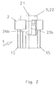
- Fig. 2:
- in horizontaler Frontansicht,
- Fig. 3:
- in der Aufsicht,
- Fig. 4:
- in einem vertikalen Halb-Schnitt entlang der vertikalen Mittelebene, also entlang der Linie A-A in Fig. 3,
- Fig. 5:
- einen vertikalen Schnitt hierzu um 90° gedreht, entlang der Linie B-B, und
- Fig. 6:
- eine Aufsicht von unten auf den Hauptkörpers des Sicherungssockels alleine.
- 1
- Sicherungssockel
- 2
- Hauptkörper
- 3
- Hülsenpaßeinsatz
- 3a
- Flansch
- 4
- Rasthaken
- 5
- Hakendurchbrüche
- 6
- Hülsensitz
- 7
- Fußkontaktschiene
- 8
- Schienenöffnung
- 9
- Gewindehülse
- 10
- Wellscheibe
- 11
- Abgangsfahne
- 12
- Abgangsklemme
- 13
- Sicherungseinsatz
- 14
- Schraubkappe
- 15
- Abflachung
- 16
- Sicherungsraum
- 17
- Gegenfläche
- 18
- Einbaublock
- 19
- Gewinde
- 20
- Mittelebene
- 21
- Vertikalrichtung
- 22
- Gewindeteil
- 23a, 23b
- Befestigungsfortsatz
- 24a, 24b
- Umfangsnase
Claims (15)
- Sicherungssockel, insbesondere zum Anordnen in einem Einbaublock eines Anschlußkastens, miteinem isolierenden Hauptkörper (2) mit einem nach oben offenen Sicherungsraum (16),einer Gewindehülse (9), undeiner Schienenöffnung (8) im Hauptkörper (2) zum Einführen einer Fußkontaktschiene (7) in den unteren Bereich des Sicherungsraumes (16),
dadurch gekennzeichnet, daß
die Schienenöffnung (8) so dimensioniert ist, daß die Fußkontaktschiene (7) unter Winkelabweichung gegenüber der vertikalen Mittelebene (20) in den Hauptkörper (2) eingeführt werden kann. - Sicherungssockel nach Anspruch 1,
dadurch gekennzeichnet, daß
die mögliche Winkelabweichung ± 45°, insbesondere ± 20° insbesondere ± 15° von der Mittelebene (20) betragt. - Sicherungssockel, insbesondere zum Anordnen in einem Einbaublock eines Anschlußkastens, miteinem isolierenden Hauptkörper (2) mit einem nach oben offenen Sicherungsraum (16),einer Gewindehülse (9),einer Schienenöffnung (8) im Hauptkörper (2) zum Einführen einer Fußkontaktschiene (7) in den unteren Bereich des Sicherungsraumes (16), undeinen Hülsenpaßeinsatz (3), der in den Sicherungsraum (16) einsetzbar ist, insbesondere nach Anspruch 1 oder 2,
dadurch gekennzeichnet, daß
der Hauptkörper (2) nach außen, insbesondere nach unten sowie zum Sicherungsraum (16) hin offene Hakendurchbrüche (5) aufweist, und der in den Sicherungsraum (16) eingesetzte Hülsenpaßeinsatz (3) einen radial nach außen vorstehenden Flansch (3a) aufweist, welcher von den in die Hakendurchbrüche (5) hineinragenden Rasthaken (4), welche vom aufnehmenden Bauteil abragen, hintergriffen wird und damit den Hülsenpaßeinsatz (3) bezüglich des Hauptkörpers (2) positionieren. - Sicherungssockel nach Anspruch 3,
dadurch gekennzeichnet, daß
der Hülsenpaßeinsatz (3) auf einem horizontalen Hülsensitz (6) des Hauptkörpers aufliegt, und mittels der Rasthaken (4) an diesem angeordnet gehalten wird. - Sicherungssockel nach einem der vorhergehenden Ansprüche,
dadurch gekennzeichnet, daß
die Schienenöffnung (8) lediglich zur Mantelfläche des Hauptkörpers (2) hin offen, zum stirnseitigen unteren Ende des Hauptkörpers (2) jedoch geschlossen und von dem Hauptkörper (2) gegenüber der Umgebung getrennt ist. - Sicherungssockel nach einem der vorhergehenden Ansprüche,
dadurch gekennzeichnet, daß
sich zwei Hakendurchbrüche (5) beidseits des Hülsensitzes (6) symmetrisch befinden. - Sicherungssockel, insbesondere zum Anordnen in einem Einbaublock eines Anschlußkastens, miteinem isolierenden Hauptkörper (2) mit einem nach oben offenen Sicherungsraum (16),einer Gewindehülse (9), undeiner Schienenöffnung (8) im Hauptkörper (2) zum Einführen einer Fußkontaktschiene (7) in den unteren Bereich des Sicherungsraumes (16), insbesondere nach einem der vorhergehenden Ansprüche,
dadurch gekennzeichnet, daß
die Gewindehülse (9) mittels Bajonettverschluß auf dem oberen Ende des Hauptkörpers (2) befestigbar ist. - Sicherungssockel nach einem der vorhergehenden Ansprüche,
dadurch gekennzeichnet, daß
die Gewindehülse (9) nach Aufsetzen auf das obere Ende des Hauptkörpers (2) durch Einbiegen von Laschen in Aussparungen des Hauptkörpers (2) gegenüber diesem fixiert wird. - Sicherungssockel nach Anspruch 7,
dadurch gekennzeichnet, daß
die Gewindehülse (9) zwei in Vertikalrichtung (21) vertikal nach unten gerichtete Befestigungsfortsätze (23a, 23b) aufweist, an deren unteren Ende in die gleiche Umfangsrichtung abstrebende Umfangsnasen (24a, 24b) abstreben. - Sicherungssockel nach Anspruch 9,
dadurch gekennzeichnet, daß
von einem der Befestigungsfortsätze (23b) radial nach außen eine Abgangsfahne (11) abragt. - Sicherungssockel nach Anspruch 10,
dadurch gekennzeichnet, daß
der Gewindeteil (22), die Befestigungsfortsätze (23a, 23b), die Umfangsnasen (24a, 324b) sowie die Abgangsfahne (11) einstückig miteinander die Gewindehülse (9) bilden. - Sicherungssockel nach einem der vorhergehenden Ansprüche,
dadurch gekennzeichnet, daß
im montierten Zustand zwischen der Gewindehülse (9) und dem Hauptkörper (2) eine ringförmige, in Vertikalrichtung (21) auf Druck belastbare Wellscheibe (10) eingelegt ist. - Sicherungssockel nach einem der vorhergehenden Ansprüche,
dadurch gekennzeichnet, daß
der Hauptkörper (2) symmetrisch beidseits der Mittelebene (20) wenigstens in seinem unteren Bereich Abflachungen (15) des Außenumfanges aufweist. - Sicherungssockel nach Anspruch 13,
dadurch gekennzeichnet, daß
die Abflachungen im Außenbereich im Schnitt quer zur Vertikalrichtung konvex V-förmig ausgebildet sind. - Sicherungssockel nach Anspruch 13 oder 14,
dadurch gekennzeichnet, daß
die Abflachungen (15) von unten wenigstens bis zur Oberkante der Abgangsfahne (11) der Gewindehülse (9) im montierten Zustand nach oben reichen.
Applications Claiming Priority (2)
| Application Number | Priority Date | Filing Date | Title |
|---|---|---|---|
| DE29720358U DE29720358U1 (de) | 1997-11-17 | 1997-11-17 | Sicherungssockel |
| DE29720358U | 1997-11-17 |
Publications (3)
| Publication Number | Publication Date |
|---|---|
| EP0917267A2 true EP0917267A2 (de) | 1999-05-19 |
| EP0917267A3 EP0917267A3 (de) | 1999-09-29 |
| EP0917267B1 EP0917267B1 (de) | 2003-07-23 |
Family
ID=8048732
Family Applications (1)
| Application Number | Title | Priority Date | Filing Date |
|---|---|---|---|
| EP98107747A Expired - Lifetime EP0917267B1 (de) | 1997-11-17 | 1998-04-28 | Sicherungssockel |
Country Status (3)
| Country | Link |
|---|---|
| EP (1) | EP0917267B1 (de) |
| AT (1) | ATE245861T1 (de) |
| DE (2) | DE29720358U1 (de) |
Family Cites Families (12)
| Publication number | Priority date | Publication date | Assignee | Title |
|---|---|---|---|---|
| DE412934C (de) * | 1925-05-02 | Siemens Schuckertwerke G M B H | Unverwechselbarkeitssystem fuer Schraubstoepselsicherungen | |
| DE968022C (de) * | 1952-09-11 | 1958-01-09 | Christian Geyer K G | Sicherungselement fuer Stromverteilungstafeln |
| DE961728C (de) * | 1954-06-26 | 1957-04-11 | Philips Nv | Fassung fuer elektrische Geraete mit Schraubensockel, insbesondere Schraubensicherungsfassung |
| DE1788097U (de) * | 1958-11-04 | 1959-05-06 | Bbc Brown Boveri & Cie | Sicherungselement, vorzugsweise fuer hausanschluss-sicherungskaesten. |
| CH378983A (de) * | 1960-07-21 | 1964-06-30 | Weber Ag Fab Elektro | Sicherungselement |
| DE1876092U (de) * | 1963-01-19 | 1963-07-25 | Bbc Brown Boveri & Cie | Sicherungselement an stromschienen. |
| DE1588520A1 (de) * | 1967-01-07 | 1970-12-23 | Aloys Mennekes Elektrotechn | Sicherungssockel zum Befestigen an einer Tragschiene |
| DE1588962A1 (de) * | 1967-01-20 | 1970-08-06 | Zimmermann Kg Rudolf | Sicherungselement zur Befestigung auf stromfuehrenden Sammelschienen |
| DE7006718U (de) * | 1970-02-24 | 1970-05-27 | Zimmermann Kg Rudolf | Sicherungssockel mit einer mittels einer feder gehalterten passhuelse. |
| DE2505353A1 (de) * | 1975-02-08 | 1976-08-19 | Bbc Brown Boveri & Cie | Schraubsicherungssockel |
| SE426996B (sv) * | 1981-07-13 | 1983-02-21 | Asea Ab | Gengsekringselement |
| NL8501162A (nl) * | 1985-04-22 | 1986-11-17 | Odink & Koenderink Bv | Zekeringhouder. |
-
1997
- 1997-11-17 DE DE29720358U patent/DE29720358U1/de not_active Expired - Lifetime
-
1998
- 1998-04-28 DE DE59809073T patent/DE59809073D1/de not_active Expired - Lifetime
- 1998-04-28 AT AT98107747T patent/ATE245861T1/de not_active IP Right Cessation
- 1998-04-28 EP EP98107747A patent/EP0917267B1/de not_active Expired - Lifetime
Also Published As
| Publication number | Publication date |
|---|---|
| DE29720358U1 (de) | 1998-01-15 |
| EP0917267A3 (de) | 1999-09-29 |
| DE59809073D1 (de) | 2003-08-28 |
| EP0917267B1 (de) | 2003-07-23 |
| ATE245861T1 (de) | 2003-08-15 |
Similar Documents
| Publication | Publication Date | Title |
|---|---|---|
| DE3201302A1 (de) | Schraubenhaltende und ausrichtende abdeckplatte | |
| EP3649353B1 (de) | Befestigungsanordnung | |
| DE19523932C2 (de) | Verliersicherung für in Bauteile lose eingesetzte Schrauben | |
| EP1177387A1 (de) | Verbindungselement | |
| EP3586013B1 (de) | Befestigungsbaugruppe | |
| DE10009978A1 (de) | Vorrichtung zur Befestigung einer Fahrzeugantenne | |
| EP2304250B1 (de) | Schraubclip | |
| WO2015131875A1 (de) | Befestigungselement für einen stromsensor | |
| DE102019206750B4 (de) | Vorrichtung zum Ausgleichen von Toleranzen zwischen einem ersten Bauteil und einem zweiten Bauteil | |
| DE29804559U1 (de) | Mechanisches Verbindungselement | |
| EP0917267B1 (de) | Sicherungssockel | |
| DE3807626C2 (de) | ||
| DE102017103770A1 (de) | Befestigungsvorrichtung und Befestigungsbaugruppe | |
| EP2767659A2 (de) | Höhenverstellbare Rundstangenführung | |
| DE69305423T2 (de) | Verkehrszeichen | |
| EP1746686B1 (de) | Elektrisches Anschlusselement | |
| EP0638462B1 (de) | Stützfuss für Dachlastenträger für Kraftfahrzeuge | |
| EP4019819A1 (de) | Vorrichtung mit zwei bauteilen, insbesondere schelle mit einem schellenring | |
| AT396005B (de) | Befestigungselement mit einer duebelartigen buchse | |
| EP3045743A1 (de) | Tragstrukturhalterung für einen fluidverteiler, montageanordnung und verfahren zur montage eines fluidverteilers | |
| EP3926762B1 (de) | Schutzkontaktsteckdose | |
| EP2262071B1 (de) | Kabeldurchführung | |
| EP3084860B1 (de) | Batterieklemme | |
| DE19724242C2 (de) | Mutter | |
| EP0412302B1 (de) | Vorrichtung zum Befestigen eines versenkt in eine Gerätetafel eingebauten Gerätes |
Legal Events
| Date | Code | Title | Description |
|---|---|---|---|
| PUAI | Public reference made under article 153(3) epc to a published international application that has entered the european phase |
Free format text: ORIGINAL CODE: 0009012 |
|
| AK | Designated contracting states |
Kind code of ref document: A2 Designated state(s): AT DE DK FR LU NL |
|
| AX | Request for extension of the european patent |
Free format text: AL;LT;LV;MK;RO;SI |
|
| PUAL | Search report despatched |
Free format text: ORIGINAL CODE: 0009013 |
|
| AK | Designated contracting states |
Kind code of ref document: A3 Designated state(s): AT BE CH CY DE DK ES FI FR GB GR IE IT LI LU MC NL PT SE |
|
| AX | Request for extension of the european patent |
Free format text: AL;LT;LV;MK;RO;SI |
|
| 17P | Request for examination filed |
Effective date: 19991126 |
|
| AKX | Designation fees paid |
Free format text: AT DE DK FR LU NL |
|
| 17Q | First examination report despatched |
Effective date: 20020807 |
|
| GRAH | Despatch of communication of intention to grant a patent |
Free format text: ORIGINAL CODE: EPIDOS IGRA |
|
| GRAH | Despatch of communication of intention to grant a patent |
Free format text: ORIGINAL CODE: EPIDOS IGRA |
|
| RAP1 | Party data changed (applicant data changed or rights of an application transferred) |
Owner name: PAUL JORDAN ELEKTROTECHNISCHE FABRIK,GMBH & CO |
|
| RAP1 | Party data changed (applicant data changed or rights of an application transferred) |
Owner name: TYCO ELECTRONICS RAYCHEM GMBH |
|
| GRAA | (expected) grant |
Free format text: ORIGINAL CODE: 0009210 |
|
| AK | Designated contracting states |
Designated state(s): AT DE DK FR LU NL |
|
| PG25 | Lapsed in a contracting state [announced via postgrant information from national office to epo] |
Ref country code: FR Free format text: LAPSE BECAUSE OF FAILURE TO SUBMIT A TRANSLATION OF THE DESCRIPTION OR TO PAY THE FEE WITHIN THE PRESCRIBED TIME-LIMIT Effective date: 20030723 |
|
| REF | Corresponds to: |
Ref document number: 59809073 Country of ref document: DE Date of ref document: 20030828 Kind code of ref document: P |
|
| PG25 | Lapsed in a contracting state [announced via postgrant information from national office to epo] |
Ref country code: DK Free format text: LAPSE BECAUSE OF FAILURE TO SUBMIT A TRANSLATION OF THE DESCRIPTION OR TO PAY THE FEE WITHIN THE PRESCRIBED TIME-LIMIT Effective date: 20031023 |
|
| PG25 | Lapsed in a contracting state [announced via postgrant information from national office to epo] |
Ref country code: LU Free format text: LAPSE BECAUSE OF NON-PAYMENT OF DUE FEES Effective date: 20040428 Ref country code: AT Free format text: LAPSE BECAUSE OF NON-PAYMENT OF DUE FEES Effective date: 20040428 |
|
| PLBE | No opposition filed within time limit |
Free format text: ORIGINAL CODE: 0009261 |
|
| STAA | Information on the status of an ep patent application or granted ep patent |
Free format text: STATUS: NO OPPOSITION FILED WITHIN TIME LIMIT |
|
| 26N | No opposition filed |
Effective date: 20040426 |
|
| EN | Fr: translation not filed | ||
| PGFP | Annual fee paid to national office [announced via postgrant information from national office to epo] |
Ref country code: NL Payment date: 20100424 Year of fee payment: 13 |
|
| REG | Reference to a national code |
Ref country code: NL Ref legal event code: V1 Effective date: 20111101 |
|
| PG25 | Lapsed in a contracting state [announced via postgrant information from national office to epo] |
Ref country code: NL Free format text: LAPSE BECAUSE OF NON-PAYMENT OF DUE FEES Effective date: 20111101 |
|
| REG | Reference to a national code |
Ref country code: DE Ref legal event code: R082 Ref document number: 59809073 Country of ref document: DE Representative=s name: WEICKMANN & WEICKMANN PATENT- UND RECHTSANWAEL, DE Ref country code: DE Ref legal event code: R082 Ref document number: 59809073 Country of ref document: DE Representative=s name: WEICKMANN & WEICKMANN PATENTANWAELTE - RECHTSA, DE Ref country code: DE Ref legal event code: R082 Ref document number: 59809073 Country of ref document: DE Representative=s name: PATENTANWAELTE WEICKMANN & WEICKMANN, DE |
|
| PGFP | Annual fee paid to national office [announced via postgrant information from national office to epo] |
Ref country code: DE Payment date: 20170427 Year of fee payment: 20 |
|
| REG | Reference to a national code |
Ref country code: DE Ref legal event code: R071 Ref document number: 59809073 Country of ref document: DE |