EP0917286A2 - Verfahren und Vorrichtung zur Rauschsperre in Schmalband-Radioempfängern - Google Patents
Verfahren und Vorrichtung zur Rauschsperre in Schmalband-Radioempfängern Download PDFInfo
- Publication number
- EP0917286A2 EP0917286A2 EP98120766A EP98120766A EP0917286A2 EP 0917286 A2 EP0917286 A2 EP 0917286A2 EP 98120766 A EP98120766 A EP 98120766A EP 98120766 A EP98120766 A EP 98120766A EP 0917286 A2 EP0917286 A2 EP 0917286A2
- Authority
- EP
- European Patent Office
- Prior art keywords
- signal
- audio
- squelch
- sub
- output
- Prior art date
- Legal status (The legal status is an assumption and is not a legal conclusion. Google has not performed a legal analysis and makes no representation as to the accuracy of the status listed.)
- Withdrawn
Links
- 230000005236 sound signal Effects 0.000 claims description 5
- 238000006243 chemical reaction Methods 0.000 description 7
- 230000006870 function Effects 0.000 description 3
- 230000005540 biological transmission Effects 0.000 description 1
- 230000007423 decrease Effects 0.000 description 1
- 230000007812 deficiency Effects 0.000 description 1
- 230000009977 dual effect Effects 0.000 description 1
- 238000012986 modification Methods 0.000 description 1
- 230000004048 modification Effects 0.000 description 1
Images
Classifications
-
- H—ELECTRICITY
- H03—ELECTRONIC CIRCUITRY
- H03G—CONTROL OF AMPLIFICATION
- H03G3/00—Gain control in amplifiers or frequency changers
- H03G3/005—Control by a pilot signal
-
- H—ELECTRICITY
- H03—ELECTRONIC CIRCUITRY
- H03G—CONTROL OF AMPLIFICATION
- H03G3/00—Gain control in amplifiers or frequency changers
- H03G3/20—Automatic control
- H03G3/30—Automatic control in amplifiers having semiconductor devices
- H03G3/34—Muting amplifier when no signal is present
- H03G3/344—Muting responsive to the amount of noise (noise squelch)
Definitions
- the present invention relates to squelch systems which operate to turn off the audio output of a radio receiver when there is no received signal and to turn it on when the desired signal is present.
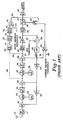
- FIG. 1 An example of a present squelch system is shown in Figure 1 wherein an AM receiver is shown having an input antenna 12 receiving broadcast signals and presenting them to an RF filter 14. Filter 14 removes all but a selected frequency and this signal is amplified by an RF amplifier 16 to produce an amplified selected RF signal.
- a first mixer 20 in conjunction with a first local oscillator 22 receives the amplified selected RF signal and converts it to a first intermediate frequency signal which is presented to an IF filter 24 to pass only the selected first IF frequency.
- This signal is amplified by IF amplifier 26 and presented to a second mixer 30 which, in conjunction with a second local oscillator 32, converts the first selected IF frequency to a second IF frequency.
- the second selected IF frequency is filtered by an IF Filter 34 and amplified by IF amplifier 36 to produce the desired AM signal on output line 37.
- IF Filter 34 An IF Filter 34
- IF amplifier 36 An IF Filter 34
- IF amplifier 36 An IF Filter 34
- IF amplifier 36 An IF Filter 34
- IF amplifier 36 An IF Filter 34
- IF amplifier 36 An IF Filter 34
- IF amplifier 36 to produce the desired AM signal on output line 37.
- the signal on output line 37 is presented to envelope detector 40 to produce the audio signal to be amplified by an audio amplifier 42 and filtered by audio filter 44 which removes some of the noise and non-speech audio that may exist in the detected signal.
- This signal is presented to an audio switch which, as will be explained, operates as a squelch switch to provide an audio output on a line 47 when there is a signal and to prevent the output on line 47 when there is no signal. More particularly, to provide the squelch function, audio switch 46 is enabled and disabled by the output of an OR gate 48. When OR gate 48 produces no output signal, switch 46 is enabled and the audio signal from filter 44 is passed through to a final audio amplifier 49 for producing an audio output to speakers or head phones (not shown) as desired. When the signal is too low or when there is too much noise in the signal, an output signal from OR gate 48 disables audio switch 46 and the signal to audio amplifier 49 is turned off.
- the output of audio amplifier 42 is also presented to a summing circuit 50 which also receives an automatic gain control threshold signal on a line 51.
- the difference is sent to an integrator 52 to produce the AGC signal for use in controlling the gain of IF amplifier 36, and, through break point amplifiers 54 and 56, controlling the gain of IF amplifier 26 and RF amplifier 16, respectively, in order to get a constant level from the envelope detector 40 that does not depend on the signal level from the antenna 12.
- a carrier squelch comparator 60 also receives the AGC signal from integrator 52 on a line 61 and compares it with a predetermined carrier squelch threshold signal on a line 62. Since the AGC voltage for a given receiver gain is an estimation of the signal level, it may be used to determine if the signal at the antenna 12 is above or below the predetermined threshold. If the AGC signal is below the threshold signal, a signal is presented by carrier switch comparator 60 on a line 62 to OR gate 48 which then disables audio switch 46 thus turning the audio output off.
- the second IF signal from IF amplifier 36 may be used to provide a noise squelch function as follows.
- the output from IF amplifier 36 on a line 64 (or the output from IF amplifier 26 on a line shown as dashed line 66) is presented to an FM discriminator 70 which performs an FM demodulation on the IF signal.
- an FM discriminator 70 which performs an FM demodulation on the IF signal.
- the noise on line 71 decreases.
- the amount of noise on the output of FM discriminator 70 is thus an indication of the signal strength for the noise squelch circuit.
- a high pass filter 72 receives this noise signal and filters away the speech frequencies and leaves only the noise at its output 73 which is presented to a noise rectifier 74 which converts it to a signal on line 75 that is proportional to the noise voltage.
- a noise squelch comparator 76 receives the signal on line 75 and compares it to a predetermined noise squelch threshold signal on a line 77. If the noise voltage on line 75 is greater than the threshold value on line 76, a signal on a line 78 is presented to OR gate 48 and the audio switch 46 is disabled and the audio output is turned off.. Thus the audio output is turned off either when the signal received by the antenna is too weak or the noise level is too high. Stated differently, the OR gate 48 enables the audio when the signal power, as measured by the AGC loop, is above a threshold of when the FM noise is below a threshold.
- the present invention uses a low frequency (sub audible) FM tone to modulate one of the local oscillators and an FM demodulator at the output of the receiver is fed to a narrow bandwidth filter that is tuned to the sub-audible tone frequency.
- a desired signal is present, an FM modulated tone will be detected by the FM demodulator.
- a desired signal is not present, only noise will be detected.
- the presence of the tone is compared to a threshold value and used to enable the receiver in the squelch circuit and the absence of a tone, indicative of there being no desired signal, will disable the receiver.
- the normal communication path of the radio contains a high pass filter that strips off any of the tone were it to manifest itself in the AM detector.
- Figure 1 The operation of Figure 1 has been set forth in the Background Of The Invention section above.
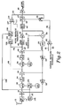
- Figure 2 most of the components operate as they did in Figure 1 and are shown with the same reference numerals.
- the different structure is shown at the left of Figure 2 where a sub-audible tone oscillator 100 generates an audio tone that is below the frequency of spoken language. The frequency is also selected so that it may easily be filtered out before it reaches the audio amplifier 49 so that it will not be heard.
- the output of oscillator 100 is shown on a line 101 connected to an FM modulator 102 which is placed between the first local oscillator 22 and the first mixer 20 so as to modulate the first local oscillator 22 slightly in frequency.
- FM modulator 102 could, instead, be placed between the second local oscillator 32 and the second mixer 30, if desired.
- phase modulation PM may be used since FM is just a time derivative of PM which for the sinusoidal tone is the same.
- a single conversion amplifier or a triple conversion amplifier may be used. In any event, when a desired signal is present at the antenna 12, the FM tone is converted to the first IF frequency (or the second IF frequency). When there is no desired signal at the antenna 12, no signal is converted to the first (or second) IF frequency.
- the output of the second IF amplifier 36 (or amplifier 26 if a single conversion amplifier is used, is connected to an FM discriminator 104 which demodulates the sub-audio tone and produces an output on a line 105 to a sub-audible detector 106 which detects if the sub-audible tone is present and, if so, creates a signal on a line 107 which is proportional to the amount of sub-audio tone present.
- the output of the sub-audible tone oscillator 100 may also be connected by a line 108 to the sub-audio tone detector 106 so as to provide the frequency information thereto for operation at the same frequency.
- a squelch comparator 110 receives the signal on line 107 and compares it to a preselected tone squelch threshold signal on a line 111. If the magnitude of the sub-audio tone present on line 107 is greater than the threshold on line 11, a signal from comparator 110 on line 115 to OR gate 48 causes the disabling of audio switch 46 and the shutting off of the audio output. In other words, OR gate 48 enables the audio when the signal power, as measured by the AGC loop, is above a threshold or when the sub-audio tone is below a threshold.
- the system is substantially immune from common transmitter and receiver deficiencies such as undesired FM of PM modulation that some AM transmitters may generate and which might disrupt the squelch systems and is immune form hum since the sub audible frequencies are far away from those in adjacent channels.
- the system is also compatible with existing channel allocations as well as new allocations and has the same advantages regarding jamming and interference as the prior art system had. Many changes and modifications will occur to those having skill in the art.
- the sub-audible tone oscillator and the FM modulator 102 may be placed between the second local oscillator 32 and the second mixer 30, the second mixer 30 and the second local oscillator 32 may be omitted if a single conversion amplifier is used and PM may be employed rather than FM to modulate the sub-audible tone.
- many of the individual components may be interchanged with others having similar functions and, the system, while designed primarily for AM radios, may also be used on narrow band FM systems as well. Accordingly, we do not wish to be limited to the specific structures used in connection with the description of the preferred embodiment.
Landscapes
- Noise Elimination (AREA)
Applications Claiming Priority (2)
| Application Number | Priority Date | Filing Date | Title |
|---|---|---|---|
| US08/966,147 US6374095B1 (en) | 1997-11-07 | 1997-11-07 | Method and apparatus for providing a squelch function on narrow band radio receivers |
| US966147 | 1997-11-11 |
Publications (2)
| Publication Number | Publication Date |
|---|---|
| EP0917286A2 true EP0917286A2 (de) | 1999-05-19 |
| EP0917286A3 EP0917286A3 (de) | 2001-01-10 |
Family
ID=25510982
Family Applications (1)
| Application Number | Title | Priority Date | Filing Date |
|---|---|---|---|
| EP98120766A Withdrawn EP0917286A3 (de) | 1997-11-07 | 1998-11-02 | Verfahren und Vorrichtung zur Rauschsperre in Schmalband-Radioempfängern |
Country Status (2)
| Country | Link |
|---|---|
| US (1) | US6374095B1 (de) |
| EP (1) | EP0917286A3 (de) |
Cited By (2)
| Publication number | Priority date | Publication date | Assignee | Title |
|---|---|---|---|---|
| EP2141817A3 (de) * | 2008-07-03 | 2014-04-30 | Honeywell International Inc. | Rauschmessung für eine Funkrauschunterdrückungsfunktion |
| EP2738938A1 (de) * | 2012-11-29 | 2014-06-04 | Nxp B.V. | Audiosystem |
Families Citing this family (5)
| Publication number | Priority date | Publication date | Assignee | Title |
|---|---|---|---|---|
| US6671504B1 (en) * | 2000-09-29 | 2003-12-30 | Northrop Grumman Corporation | Radio squelch techniques |
| EP1679802A1 (de) * | 2005-01-07 | 2006-07-12 | Success Chip Ltd., c/o Offshore Incorporations Ltd., P.O. Box 957, Offshore Incorporations Center | Verfahren und Schaltung zum Erzeugen und Detektieren eines Sendesignals |
| US7460847B2 (en) * | 2005-09-01 | 2008-12-02 | Sigmatel, Inc. | Handheld audio system with radio receiver and method for use therewith |
| JP7000755B2 (ja) * | 2017-09-12 | 2022-01-19 | 株式会社Jvcケンウッド | 受信機及びノイズスケルチ制御方法 |
| US20200012347A1 (en) * | 2018-07-09 | 2020-01-09 | Immersion Corporation | Systems and Methods for Providing Automatic Haptic Generation for Video Content |
Family Cites Families (11)
| Publication number | Priority date | Publication date | Assignee | Title |
|---|---|---|---|---|
| US2766324A (en) * | 1951-12-18 | 1956-10-09 | Motorola Inc | Switching system |
| US3131354A (en) * | 1961-06-12 | 1964-04-28 | Motorola Inc | Tone control receiver circuit |
| US3623106A (en) * | 1969-07-03 | 1971-11-23 | Motorola Inc | Multifrequency receiver employing tone-coded squelch with automatic channel selection |
| US3733554A (en) * | 1971-03-19 | 1973-05-15 | K Wycoff | Communication receiver with tone operated audio amplifier circuitry |
| US3810023A (en) * | 1972-07-21 | 1974-05-07 | Rca Corp | Automatic squelch tail eliminator for tone coded squelch systems |
| US4063033A (en) * | 1975-12-30 | 1977-12-13 | Rca Corporation | Signal quality evaluator |
| US4541118A (en) * | 1983-12-22 | 1985-09-10 | Motorola, Inc. | SSB System with pilot coded squelch |
| JPH0522170A (ja) | 1991-07-17 | 1993-01-29 | Nec Corp | スケルチ制御回路 |
| US5481545A (en) * | 1991-08-26 | 1996-01-02 | Ericsson Inc. | Conventional network interface for multisite RF trunking system |
| FR2716766B1 (fr) | 1994-02-25 | 1996-03-22 | Thomson Csf | Procédé et dispositif de contrôle automatique de gain de circuits de réception. |
| US5970399A (en) * | 1995-11-22 | 1999-10-19 | Telefonaktiebolaget Lm Ericsson | Radio channel squelching systems |
-
1997
- 1997-11-07 US US08/966,147 patent/US6374095B1/en not_active Expired - Fee Related
-
1998
- 1998-11-02 EP EP98120766A patent/EP0917286A3/de not_active Withdrawn
Cited By (3)
| Publication number | Priority date | Publication date | Assignee | Title |
|---|---|---|---|---|
| EP2141817A3 (de) * | 2008-07-03 | 2014-04-30 | Honeywell International Inc. | Rauschmessung für eine Funkrauschunterdrückungsfunktion |
| EP2738938A1 (de) * | 2012-11-29 | 2014-06-04 | Nxp B.V. | Audiosystem |
| US9331650B2 (en) | 2012-11-29 | 2016-05-03 | Nxp B.V. | Audio system |
Also Published As
| Publication number | Publication date |
|---|---|
| US6374095B1 (en) | 2002-04-16 |
| EP0917286A3 (de) | 2001-01-10 |
Similar Documents
| Publication | Publication Date | Title |
|---|---|---|
| US5339454A (en) | Automatic gain control for RF amplifier | |
| US4539707A (en) | Compressed single side band communications system and method | |
| US4541118A (en) | SSB System with pilot coded squelch | |
| US5745845A (en) | Receiver with automatic receiving-station switching function | |
| JPH06509691A (ja) | ラジオ受信機用の隣接チャネル・コントローラ | |
| US4811423A (en) | SSB receiver with improved feedforward AGC | |
| US4584708A (en) | Communication system, and transmitter therefor, including special announcement recognition | |
| US5465406A (en) | Automatic gain control overshoot limiter for AM receiver | |
| US5991603A (en) | Narrow-band communication apparatus | |
| US6374095B1 (en) | Method and apparatus for providing a squelch function on narrow band radio receivers | |
| US4498195A (en) | Radio interference detection device for use in a multi-channel access angle-modulation radio system | |
| KR101328957B1 (ko) | 무선 마이크 수신기 및 혼신 방지 방법 | |
| WO1993020622A1 (en) | Squelch detector | |
| JP4159964B2 (ja) | オーディオ放送受信装置及び自動選局方法 | |
| US3824470A (en) | Communications system and method for transmitting over a limited bandwidth transmission link | |
| US4829588A (en) | Automatic retransmission with pilot tone | |
| US8498596B2 (en) | FM signal quality measurement | |
| US4355417A (en) | Squelch control circuit for amplitude modulated RF receivers | |
| CA1042515A (en) | Information signal transmitting system | |
| US7133468B2 (en) | Concurrent FM signal receiver | |
| JP3652821B2 (ja) | フィルタの所定帯域幅の帯域端周波数検出装置と当該装置を用いたssb送信機およびssb受信機 | |
| JPH0516733Y2 (de) | ||
| JP3180750B2 (ja) | 携帯無線機 | |
| EP0132307A2 (de) | Empfänger mit Störsperre | |
| JPH0214820B2 (de) |
Legal Events
| Date | Code | Title | Description |
|---|---|---|---|
| PUAI | Public reference made under article 153(3) epc to a published international application that has entered the european phase |
Free format text: ORIGINAL CODE: 0009012 |
|
| AK | Designated contracting states |
Kind code of ref document: A2 Designated state(s): DE FR GB IT |
|
| AX | Request for extension of the european patent |
Free format text: AL;LT;LV;MK;RO;SI |
|
| PUAL | Search report despatched |
Free format text: ORIGINAL CODE: 0009013 |
|
| AK | Designated contracting states |
Kind code of ref document: A3 Designated state(s): AT BE CH CY DE DK ES FI FR GB GR IE IT LI LU MC NL PT SE |
|
| AX | Request for extension of the european patent |
Free format text: AL;LT;LV;MK;RO;SI |
|
| RIC1 | Information provided on ipc code assigned before grant |
Free format text: 7H 03G 3/34 A, 7H 03G 3/00 B |
|
| 17P | Request for examination filed |
Effective date: 20001128 |
|
| AKX | Designation fees paid |
Free format text: DE FR GB IT |
|
| GRAP | Despatch of communication of intention to grant a patent |
Free format text: ORIGINAL CODE: EPIDOSNIGR1 |
|
| STAA | Information on the status of an ep patent application or granted ep patent |
Free format text: STATUS: THE APPLICATION IS DEEMED TO BE WITHDRAWN |
|
| 18D | Application deemed to be withdrawn |
Effective date: 20050405 |