EP0917348A2 - Fehlerdiffusion mit Subpixelmodulation für die Graustufenwiedergabe von kontinuierlichen Bildtonwerten - Google Patents
Fehlerdiffusion mit Subpixelmodulation für die Graustufenwiedergabe von kontinuierlichen Bildtonwerten Download PDFInfo
- Publication number
- EP0917348A2 EP0917348A2 EP98120844A EP98120844A EP0917348A2 EP 0917348 A2 EP0917348 A2 EP 0917348A2 EP 98120844 A EP98120844 A EP 98120844A EP 98120844 A EP98120844 A EP 98120844A EP 0917348 A2 EP0917348 A2 EP 0917348A2
- Authority
- EP
- European Patent Office
- Prior art keywords
- pixel
- error
- pixels
- value
- image
- Prior art date
- Legal status (The legal status is an assumption and is not a legal conclusion. Google has not performed a legal analysis and makes no representation as to the accuracy of the status listed.)
- Withdrawn
Links
Images


Classifications
-
- H—ELECTRICITY
- H04—ELECTRIC COMMUNICATION TECHNIQUE
- H04N—PICTORIAL COMMUNICATION, e.g. TELEVISION
- H04N1/00—Scanning, transmission or reproduction of documents or the like, e.g. facsimile transmission; Details thereof
- H04N1/40—Picture signal circuits
- H04N1/405—Halftoning, i.e. converting the picture signal of a continuous-tone original into a corresponding signal showing only two levels
- H04N1/4051—Halftoning, i.e. converting the picture signal of a continuous-tone original into a corresponding signal showing only two levels producing a dispersed dots halftone pattern, the dots having substantially the same size
- H04N1/4052—Halftoning, i.e. converting the picture signal of a continuous-tone original into a corresponding signal showing only two levels producing a dispersed dots halftone pattern, the dots having substantially the same size by error diffusion, i.e. transferring the binarising error to neighbouring dot decisions
Definitions
- This invention relates to binary processes for rendering continuous tone images and, more particularly, to an improved error diffusion process for a gray scale rendering of such images.
- Error diffusion is a well known technique for rendering a continuous tone image to a image-like binary pattern of dots for the purpose of printing or displaying the image on a binary device. Since error diffusion require a pre-designed threshold array as in the traditional clustered-dot screening techniques, there is no particular structured cell associated with the resulting binary image, which means that it is better suited for rendering high frequency detail. Hence the error diffusion is often the preferred method of rendering for low to medium resolution binary rendering engines (e.g., those that render images at about 600 dots per inch or less).
- this invention provides enhancements and modifications to an error diffusion process described in Japanese Patent Application No. (Attorney Docket No. D/97498) which significantly improve the output quality.
- the proposed method offers a new and effective technique to greatly reduce the objectionable properties (i)-(iii) listed above by introducing sub-pixel or variable dot size modulation.
- the result is similar to the affect of applying Hewlett-Packard's (HP's) so-called REt ( Resolution Enhancement ) technology for enhancing text quality on low resolution output devices.
- HP's Hewlett-Packard's
- REt Resolution Enhancement
- invention is built on two important concepts: a) utilizing gray pixels ("gray dots") by means of sub-pixel or variable dot size modulation; and b) using a generic printer model to match the error diffusion to the non-ideal output device.
- Xerographic and inkjet printers are examples of the binary rendering engines with which this invention may be employed to advantage
- error diffusion typically involves a single pass over the input image, during which each pixel is processed sequentially. This processing thresholds the input pixel value and replaces it with one of two values, an "on” or an "off". As each pixel is replaced, an error may be introduced to the local gray level of the image. Therefore, this error is compensated by adjusting the values of the neighboring pixels to preserve the local gray level prior to thresholding. In order to avoid multiple passes over the image, the error is only propagated (or "diffused") among future pixels that have not been processed yet (e.g., to pixels located to the right and below the current pixel for a left-to-right scan order).
- Fig. 1 which comes from work of Floyd & Steinberg, demonstrates the principles of error diffusion (the squares represent the input image pixels on a raster grid).
- the pixels in black and white were already processed, thresholded, and binarized to be either on or off, while the shaded pixels have not yet been processed.
- the center pixel which is surrounded by a dark frame, is the current pixel to be processed next.
- the arrows leading from the current pixel indicate how the current thresholding error is to be distributed to the neighboring pixels. It is often referred to as the error diffusion filter in the literature.
- the numbers along the arrows describe the [possibly varying] non-normalized relative neighbor weight.
- the number 7 associated with the pixel immediately to the right of the current pixel indicates that 7/16 of the error will be used to adjust this pixel, where 16 is the normalization factor equal to the total sum of the weights.
- 16 is the normalization factor equal to the total sum of the weights.
- a conventional error diffusion technique involves the following three basic steps: A thresholding step in which the current pixel is compared with a given threshold; followed by an error compensation step, where the error is adjusted by subtracting the binary output level; and finally, the error is distributed to the neighboring pixels. The process then advances by one pixel and repeats.
- the error diffusion technique was originally designed for binary output devices, whose outcome can only be either on or off.
- the technique has since been extended to support multi-level output devices in a straightforward manner.
- the extension to multi-level error diffusion requires multiple decisions per pixel.
- N-1 thresholds for the error compensation step.
- the incoming value is compared to a sequence of up to N-1 pre-determined thresholds. As long as the incoming value is larger than the current threshold, the process advances to the next threshold and repeats.
- the comparison cycle is halted and the corresponding gray level is outputted.
- the error between the incoming value and the output value is then calculated and distributed as before.
- the thresholds are generally uniformly distributed between 0 and 255 (assuming 8-bit representation).
- N-level error diffusion typically increases the system complexity roughly linearly with N.
- the resulting image quality usually does not increase in a similar fashion.
- a marking engine is typically designed to be used as a binary device, and is not capable of consistently reproducing single-pixel gray levels.
- xerography provides a useful example of how the knowledge of the printing process comes into play.
- standard xerography is a complicated process which is influenced by a large number of variables, such as temperature, humidity, toner characteristics, developer voltages, etc. Even if all of these variables could be precisely controlled, there is also is noise in the system, introducing variations in dot position (jitter), dot gain (density), dot shape, and dot-to-dot interaction. Consequently it would be very difficult, if not impossible, to precisely characterize the xerography process. And even if it could be accurately modeled, the model would tend to be extremely sensitive to small deviations in variable values. That, of course is contrary to the goal of providing a simple and effective rendering process that is robust and does not rely on such a complicated model. Clearly, however, the rendering process should leverage the common properties of the underlying rendering engine to its advantage.
- an ordinary xerographic laser marking device charges a drum or transfer belt photoreceptor with uniform charge.
- a focused laser beam then scans over the photoreceptor in raster order, selectively erasing the charge in those locations where the laser is turned on.
- the latent image is developed, transferred to the paper media, and fused.
- a marking device of this type typically is driven by modulating the laser power between the (binary) levels of zero (laser off) and one (full power on). This usually is accomplished by means of a single digital interface signal, commonly referred to as the video signal.
- the video signal commonly referred to as the video signal.
- the on/off timing of the laser usually is.
- the laser has no notion of fixed-width pixels, so the only requirement is that the laser power be on for a sufficient amount of time for the photoreceptor to collect enough photons to discharge.
- Xerographic engine manufacturers use a performance metric, such as "600" or "400" dpi (dots-per-inch), which is based on the minimum on time required to guarantee the outcome. It is thus relatively easy to change (within limits) the laser timing by means of replacing the driving clock frequency.
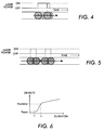
- Figs 2-5 illustrate the above-described behavior as the laser on-time duration is varied.
- Figure 2 shows a nominal pixel duration for particular marking engine (say 600 dpi).
- the duration is shorter, and if too short - no toner will adhere.
- the pulse is already wide enough to attract some toner, as illustrated in Fig. 4, a small additional increase would cause more toner to adhere, and the perceived density would increase.
- the density can be controlled more precisely than with pixels of predetermined size.
- this effect may be lost if two or more independently exposed regions or "dots" are too close to each other, where dot-to-dot interaction begins to play a role.
- a toner bridge may be formed between the dots if they are too close together, in which case the perceived density will increase at an accelerated rate, so the proportionality between the density and the individual dot sizes no longer holds.
- FIG. 6 Closer examination of Fig. 6 reveals two generally linear regions with different density slopes, one on each side of the nominal working point N , which are well suited for sub-pixel modulation.
- this invention leverages this generic behavior of xerography in and around the nominal working point to further enhance the output image quality. Even now, however, it will be evident that simply spacing the error calculation thresholds uniformly between zero and N (as assumed for conventional multi-level error-diffusion) would be suboptimal.
- Figs. 7-10 illustrate the effects of multi-dot interaction on this generic model of the xerographic printing process.
- Fig. 7 When printing highlights, such as shown in Fig. 7, there are relatively few dots per unit area, and these dots are well separated from each other. Thus, the behavior of these dots is generally consistent with the isolated-dot behavior shown in Fig. 6. As the image density increases, there are more dots per unit area, and the distance between dots shrinks. In the midtones, as shown in Fig. 8, satellites start forming as small clumps of toner along the closest distance lines. These clumps get larger as the density further increases, until permanent bridges are formed in the shadows of the image, as shown in Fig. 9.
- This invention takes advantage of the above-described understanding of the isolated-dot and dot-to-dot behaviors of xerographic marking engines to provide an error diffusion process that significantly increases the output quality of such marking engines. By leveraging this common behavior into the design of the error diffusion, one can significantly enhance the output quality. These behaviors are generic, so the error diffusion process of this invention does not rely on a precise model of the marking engine, which contributes to the robustness of the process.
- gray scale pixel values say, 8-bit unsigned integer values, from a suitable source, such as an input scanner (not shown), are written into a FIFO input buffer 21 in raster scan order, such as left-to right top-to-bottom order.
- These pixel values may be digital samples of a monotone (e.g., black and white) image or of a color separation of a polychromatic image.
- An address pointer 22 is incremented (modulo the length of the input buffer 21) to read out a current pixel value, say, x i,j for error diffused rendering upon the completion of the rendering of the preceding pixel, x i, j-1.
- the current pixel value is routed to a counter circuit 32 and to a summer 33.
- This particular implementation of the invention extends the error diffusion process described in the above-identified Kletter et al patent application to three levels of gray (i.e., black, white and an intermediate gray level) based on the generic xerographic printer model that is described hereinabove. Given this printer model, it will be evident that this intermediate or "partial pixel" level of gray is best leveraged to improve the highlight response of a xerographic printer.
- the counter circuit 32 and the associated threshold and decision logic 33 are designed to identify highlight regions of images and to control the rendering of those regions through the use of the partial pixel printing capability that is provided by the illustrated embodiment. It is to be understood, however, can be implemented to accommodate other generic printer models and/or to provide multiple intermediate levels of gray response.
- a comparator 35 at the input of the counter circuit 32 compares the current pixel value with a predetermined threshold value EDMING which is selected to be sufficiently high (i. e., trending toward white at a pixel value of 255 in this particular embodiment) to separate pixels that potentially belong to highlight regions of the image from those that do not appear to have that potential. If the pixel value exceeds this threshold, the comparator 35 increments a counter 36.
- a predetermined threshold value EDMING which is selected to be sufficiently high (i. e., trending toward white at a pixel value of 255 in this particular embodiment) to separate pixels that potentially belong to highlight regions of the image from those that do not appear to have that potential.
- the comparator 35 clears the counter 36, thereby causing the rendering of the current pixel to default to the black/white mode described in the Kletter et al application, while disabling the sub-pixel modulation process for at least EDNG subsequent pixels as more fully explained hereinbelow.
- the current pixel value is summed by a summer 41 with any horizontal and/or vertical error values that have been distributed to this pixel from previously processed pixels on the same scan line and/or on preceding scan lines (see Fig. 1).
- the accumulated horizontal error value, e x for the current pixel is shifted out of a horizontal error buffer 42, while a compressed representation of the accumulated vertical error value is shifted out of a vertical error buffer 43 and then expanded by a decompressor or expander 44.
- the horizontal and vertical error values are represented by 9-bit signed integers, thereby representing the magnitude of those errors with same precision as the pixel values are represented while also identifying the sense of the errors.
- the current pixel value as adjusted by any error that has been distributed to the current pixel, is processed as described hereinbelow to determine whether it is best represented by a white (OUTW), gray (OUTW) or black (OUTB) output pixel and is applied to an error detector 45.
- the detector 45 includes a summer 40 which calculates the difference, if any, between the adjusted pixel value and a negatively signed 9-bit integer reference value in the range of 0 - 255 that is supplied by a suitable variable reference source. Any difference that exists between those two values is output by the comparator 45 as a signed 9-bit integer error value.
- This error value is fed into a diffusion filter 51 for distribution to neighboring unprocessed pixels in accordance with a selected error distribution strategy.
- the first tap 52 of the filter 51 distributes 5/16ths of the error to the horizontal error buffer for later use in adjusting the value of right-hand neighbor, x i+1, j , of the current pixel.
- the second filter tap 53 distributes 3/16ths of the error to a summer 54 for later use in adjusting the value of the left-hand diagonal next row neighbor x i-1, j+1 .
- the third tap 54 distributes 7/16ths of the error to a summer 55 for later use in adjusting the value of the directly aligned next row neighbor, x i, j+1 , of the current pixel. And, the last tap distributes the remaining 1/16th of the error to a register 56 for later use in adjusting the value of the left-hand diagonal next row neighbor x i+1, j+1 .
- one approach is to increase the line size (and the vertical error buffer 43) by a few pixels at each end of the line, and then assume known values for these boundary pixels (typically either white or replicating the first ⁇ last pixel value).
- Another alternative is to re-target the filter taps dynamically at the line boundaries, as to not distribute error beyond the true line limits.
- the second or 3/16ths tap 53 could be re-targeted to combine with third or 7/16ths tap 54, thereby distributing 10/16ths of the error to the directly aligned next row neighboring pixel.
- the illustrated error distribution strategy permits the accumulation of a potentially large vertical error value for every pixel after the first line of an image.
- the vertically distributed error values are compressed by a compressor 61 to, say, 4-bit signed integer values before being loaded into vertical error buffer 43. Readers interested in the details of a suitable process for performing this compression may refer to the aforementioned Kletter et al. patent application
- a gray pixel output option for turning the print laser on for less than a full pixel time.
- the laser is operated near the nominal working point N for the printing process and below the knee of the laser on-time duration/image density response curve of the printer. See Fig. 6.
- the counter 36 in the counter circuit 32 is cleared whenever the current pixel value is equal to or less than (i. e., represents at least as dark a gray) as the threshold value EDMING.
- the counter 32 is incremented each time it receives a pixel value that is less than the threshold value EDMING, so its accumulated count represents the number of consecutive pixel values that have remained below (i. e., represented a lighter gray than) the EDMING threshold as of any given time during the error diffusion process.
- another comparator 72 compares the count accumulated by the counter 32 against a threshold count EDNG which is selected to be sufficiently large to confirm that the most recent pixel values represent pixels in a highlight region of the image.
- the comparator 72 provides a trigger signal which causes a decision logic 73 to enable the sub-pixel modulation mode, thereby making a third option, OUTG (output gray) available for the printing of output pixels if, but only if, those pixels reside within a region of the image that has been confirmed to be a highlight region.
- the state of the trigger signal for the decision logic 73 is changed by the comparator 72, thereby causing the error diffusion process to revert to its default mode which, as illustrated, gives the process the binary option of outputting white (OUTW) or black (OUTB).
- OUTW white
- OUTB black
- the thresholds EDMING and EDNG are both tuned in practice to accommodate the specific print engine characteristics and the desired boundary gap considerations.
- the adjusted value for the current pixel is compared against a preselected threshold T 1 by a comparator 74 to provide a signal for instructing the decision logic 73 to cause a white pixel or a black pixel to be output.
- a comparator 74 to provide a signal for instructing the decision logic 73 to cause a white pixel or a black pixel to be output.
- the decision logic 73 selects the white pixel (OUTW) output option and causes the controller 46 to set the reference value for the error detector 45 to a compensating level of 255 (to the extreme "white" end of the range) to compute any attendant error.
- the decision logic 73 selects the black pixel (OUTB) output option and provides no reference level compensation for the error detector 45 which means that the error detector uses a 0 (the black extreme) reference level for computing any error.
- the threshold value T 1 may be more or less randomly altered within a confined range of pixel values that represent mid-gray tones.
- the adjusted value for the current pixel is not only compared with the threshold T 1 , but is also compared with a second threshold value, T 2 , by a another comparator 75.
- This second threshold value, T 2 represents a lighter gray than the threshold value, T 1 .
- the decision logic 73 operates as a three-way selector to cause a black pixel (OUTB) to be output if the adjusted value of the current pixel is below the lowermost threshold T 1 , a white pixel (OUTW) to be output if the adjusted pixel value is above the uppermost threshold T 2 , or a gray pixel (OUTG) to be output if the adjusted pixel value is anywhere between those two thresholds.
- the decision logic 73 sets the reference level for the error detector 45 to the upper extreme of its range(e.g. 255) when white pixels are being output, while holding it at the lower extreme of that range (e.g., 0) when black pixels are being output.
- the decision logic 73 causes a gray pixel (OUTG) to be output and sets the reference level for the error detector 45 to the mid-range value that is stored in a register 78.
- the optimized relationship between the partial pixel or gray dot duration (as encoded in OUTG) and the reference level compensating value GCMP that is provided for the error detector 45 is again dependent on the specific print engine characteristics. If, for example, the gray dot is selected to be shorter than a full pixel, the output density will generally be lighter. Theoretically, one would determine just how dark the dot is relative to a full pixel, and from that deduce a compensation value to minimize the remaining error (i. e., the error that is further distributed to the neighboring pixels in the normal error diffusion process). In practice, the exact relationship turns out to not be critical, within limits, because the distributed error tends to cancel across multiple pixels.
- gray dot duration Another design consideration regarding the gray dot duration is the stability and repeatability of these dots on the particular engine As discussed above, if the duration is made much smaller than a full pixel, than it becomes unstable and highly dependent upon the operating environment (such as temperature, humidity, etc.), and may even cease to attract enough toner to stick if too small. If, on the other hand, the dot is not made significantly smaller than a pixel, the deviation from a single pixel density is likely to be very small, thereby causing the output image quality to approach that of the binary case. Hence, these two factors need to be taken into account and resolved to best suit the performance characteristics of the intended rendering engine.
- this invention may be applied to more sophisticated multi-level error diffusion processes. Such a process would require additional threshold comparators for the decision logic 72 and might also require provision for storing additional compensating values for the error detector 45. Conceivably, the threshold values for these additional comparators could be fixed or could vary from one pixel to the next.
Landscapes
- Engineering & Computer Science (AREA)
- Multimedia (AREA)
- Signal Processing (AREA)
- Facsimile Image Signal Circuits (AREA)
- Image Processing (AREA)
Applications Claiming Priority (2)
| Application Number | Priority Date | Filing Date | Title |
|---|---|---|---|
| US97220897A | 1997-11-17 | 1997-11-17 | |
| US972208 | 1997-11-17 |
Publications (2)
| Publication Number | Publication Date |
|---|---|
| EP0917348A2 true EP0917348A2 (de) | 1999-05-19 |
| EP0917348A3 EP0917348A3 (de) | 2002-06-19 |
Family
ID=25519348
Family Applications (1)
| Application Number | Title | Priority Date | Filing Date |
|---|---|---|---|
| EP98120844A Withdrawn EP0917348A3 (de) | 1997-11-17 | 1998-11-03 | Fehlerdiffusion mit Subpixelmodulation für die Graustufenwiedergabe von kontinuierlichen Bildtonwerten |
Country Status (2)
| Country | Link |
|---|---|
| EP (1) | EP0917348A3 (de) |
| BR (1) | BR9804661A (de) |
Cited By (1)
| Publication number | Priority date | Publication date | Assignee | Title |
|---|---|---|---|---|
| EP1646223A1 (de) * | 2004-10-11 | 2006-04-12 | Samsung Electronics Co., Ltd. | Fehlerdiffusion |
Family Cites Families (4)
| Publication number | Priority date | Publication date | Assignee | Title |
|---|---|---|---|---|
| US4969052A (en) * | 1988-05-11 | 1990-11-06 | Canon Kabushiki Kaisha | Image processing method and apparatus |
| JPH03132259A (ja) * | 1989-10-18 | 1991-06-05 | Canon Inc | 画像処理装置 |
| JP2824999B2 (ja) * | 1990-02-01 | 1998-11-18 | キヤノン株式会社 | 画像処理装置 |
| US5708514A (en) * | 1994-08-31 | 1998-01-13 | Kabushiki Kaisha Toshiba | Error diffusion method in a multi-level image recording apparatus utilizing adjacent-pixel characteristics |
-
1998
- 1998-11-03 EP EP98120844A patent/EP0917348A3/de not_active Withdrawn
- 1998-11-17 BR BR9804661A patent/BR9804661A/pt not_active IP Right Cessation
Cited By (1)
| Publication number | Priority date | Publication date | Assignee | Title |
|---|---|---|---|---|
| EP1646223A1 (de) * | 2004-10-11 | 2006-04-12 | Samsung Electronics Co., Ltd. | Fehlerdiffusion |
Also Published As
| Publication number | Publication date |
|---|---|
| BR9804661A (pt) | 1999-11-03 |
| EP0917348A3 (de) | 2002-06-19 |
Similar Documents
| Publication | Publication Date | Title |
|---|---|---|
| EP0702482B1 (de) | Fehlerdiffusionhalbtonrasterung mit homogener Ausgabe in Bildbereichen hoher/niedriger Intensität | |
| US5353127A (en) | Method for quantization gray level pixel data with extended distribution set | |
| US9361557B2 (en) | Image processing apparatus and control method for performing screen processing | |
| EP0606132A2 (de) | Fehlerdiffusion mit eingangs- und ausgangsbasierter Rückkopplung | |
| EP0781034B1 (de) | Bildverarbeitungsgerät und -verfahren | |
| US5740334A (en) | Quantization method for color document reproduction in a color printing system | |
| US5805734A (en) | Hybrid imaging system | |
| US5708514A (en) | Error diffusion method in a multi-level image recording apparatus utilizing adjacent-pixel characteristics | |
| EP0581561B1 (de) | Fehlerdiffusion hoher Adressierbarkeit und minimaler Markengrösse | |
| EP0732842B1 (de) | Bildverarbeitung zur Entfernung von Hintergrundanteilen aus Abtastdaten eines Bilddokumentes | |
| Lee et al. | Inkjet printer model-based halftoning | |
| EP1366618B1 (de) | Verfahren und system zur fehlerdiffusion bei teilhalbtonpunkten | |
| US7116445B2 (en) | Image forming apparatus and image forming method | |
| EP0817466B1 (de) | Randverbesserte Fehlerdiffusion | |
| US5598204A (en) | Image halftoning system capable of producing additional gradations | |
| US7016073B1 (en) | Digital halftone with auxiliary pixels | |
| US20020041397A1 (en) | Method of processing pixels with binary or multibit error diffusion | |
| JP5264412B2 (ja) | 画像処理装置および画像処理方法 | |
| JP5121592B2 (ja) | 画像形成装置および画像処理方法 | |
| KR20000026847A (ko) | 화상 데이터 처리장치 | |
| JP2002185785A (ja) | 画像処理方法及び装置、記録媒体 | |
| EP0917348A2 (de) | Fehlerdiffusion mit Subpixelmodulation für die Graustufenwiedergabe von kontinuierlichen Bildtonwerten | |
| US7502512B2 (en) | Image processing apparatus and image processing method | |
| US5838462A (en) | Hybrid imaging system | |
| JP4861506B2 (ja) | 画像処理装置およびその制御方法 |
Legal Events
| Date | Code | Title | Description |
|---|---|---|---|
| PUAI | Public reference made under article 153(3) epc to a published international application that has entered the european phase |
Free format text: ORIGINAL CODE: 0009012 |
|
| AK | Designated contracting states |
Kind code of ref document: A2 Designated state(s): AT BE CH CY DE DK ES FI FR GB GR IE IT LI LU MC NL PT SE |
|
| AX | Request for extension of the european patent |
Free format text: AL;LT;LV;MK;RO;SI |
|
| PUAL | Search report despatched |
Free format text: ORIGINAL CODE: 0009013 |
|
| AK | Designated contracting states |
Kind code of ref document: A3 Designated state(s): AT BE CH CY DE DK ES FI FR GB GR IE IT LI LU MC NL PT SE |
|
| AX | Request for extension of the european patent |
Free format text: AL;LT;LV;MK;RO;SI |
|
| 17P | Request for examination filed |
Effective date: 20021219 |
|
| AKX | Designation fees paid |
Designated state(s): DE FR GB |
|
| STAA | Information on the status of an ep patent application or granted ep patent |
Free format text: STATUS: THE APPLICATION IS DEEMED TO BE WITHDRAWN |
|
| 18D | Application deemed to be withdrawn |
Effective date: 20040602 |