EP0917353A2 - Verfahren zur Farbabstimmung von Farbbildverarbeitungsvorrichtungen mit Interpolation einer relativ kleinen Anzahl van Farbdatengruppen - Google Patents
Verfahren zur Farbabstimmung von Farbbildverarbeitungsvorrichtungen mit Interpolation einer relativ kleinen Anzahl van Farbdatengruppen Download PDFInfo
- Publication number
- EP0917353A2 EP0917353A2 EP98121422A EP98121422A EP0917353A2 EP 0917353 A2 EP0917353 A2 EP 0917353A2 EP 98121422 A EP98121422 A EP 98121422A EP 98121422 A EP98121422 A EP 98121422A EP 0917353 A2 EP0917353 A2 EP 0917353A2
- Authority
- EP
- European Patent Office
- Prior art keywords
- color data
- color
- data sets
- output
- input
- Prior art date
- Legal status (The legal status is an assumption and is not a legal conclusion. Google has not performed a legal analysis and makes no representation as to the accuracy of the status listed.)
- Granted
Links
- 238000000034 method Methods 0.000 title claims abstract description 30
- 239000003086 colorant Substances 0.000 claims description 71
- 238000002156 mixing Methods 0.000 description 21
- 238000006243 chemical reaction Methods 0.000 description 16
- 230000006870 function Effects 0.000 description 9
- 238000002360 preparation method Methods 0.000 description 9
- 230000000694 effects Effects 0.000 description 7
- 230000008859 change Effects 0.000 description 6
- 238000005259 measurement Methods 0.000 description 6
- 239000000654 additive Substances 0.000 description 4
- 230000000996 additive effect Effects 0.000 description 4
- 238000010586 diagram Methods 0.000 description 2
- 239000004973 liquid crystal related substance Substances 0.000 description 2
- 238000004519 manufacturing process Methods 0.000 description 2
- 239000000049 pigment Substances 0.000 description 2
- 238000013500 data storage Methods 0.000 description 1
- 238000009826 distribution Methods 0.000 description 1
- 238000012986 modification Methods 0.000 description 1
- 230000004048 modification Effects 0.000 description 1
- 230000008569 process Effects 0.000 description 1
- GGCZERPQGJTIQP-UHFFFAOYSA-N sodium;9,10-dioxoanthracene-2-sulfonic acid Chemical compound [Na+].C1=CC=C2C(=O)C3=CC(S(=O)(=O)O)=CC=C3C(=O)C2=C1 GGCZERPQGJTIQP-UHFFFAOYSA-N 0.000 description 1
- 230000003595 spectral effect Effects 0.000 description 1
- 238000003860 storage Methods 0.000 description 1
- 238000000859 sublimation Methods 0.000 description 1
- 230000008022 sublimation Effects 0.000 description 1
Images





Classifications
-
- H—ELECTRICITY
- H04—ELECTRIC COMMUNICATION TECHNIQUE
- H04N—PICTORIAL COMMUNICATION, e.g. TELEVISION
- H04N1/00—Scanning, transmission or reproduction of documents or the like, e.g. facsimile transmission; Details thereof
- H04N1/46—Colour picture communication systems
- H04N1/56—Processing of colour picture signals
- H04N1/60—Colour correction or control
- H04N1/6058—Reduction of colour to a range of reproducible colours, e.g. to ink- reproducible colour gamut
-
- H—ELECTRICITY
- H04—ELECTRIC COMMUNICATION TECHNIQUE
- H04N—PICTORIAL COMMUNICATION, e.g. TELEVISION
- H04N1/00—Scanning, transmission or reproduction of documents or the like, e.g. facsimile transmission; Details thereof
Definitions
- the present invention relates a method of effecting color matching between an input color data batch inputted to a color image input device and an output color data batch outputted from a color image output device, or between output color data batches outputted from a plurality of color image output devices which are operated according to the same input color data batch.
- color image output devices such as a CRT (cathode ray tube) display, a color printer and a color copier, which are adapted to reproduce a color image according to an image data batch (internal color data) received from an color image input device such as a color scanner, a digital camera or a digital video camera, which is adapted to read or obtain an original color image (external color data as viewed by an observer).
- the image data batch or external color data batch consists of a multiplicity of pixel color data sets representative of colors at respective picture elements which collectively define a color image.
- the original color image (external color data) is reproduced based on those pixel color data sets.
- a color image output device as indicated above is capable of reproducing various colors by mixing three pigments having respective three colors consisting of yellow (Y), magenta (M) and cyan (C), or four pigments having respective four colors consisting of yellow, magenta, cyan and black (K), or alternatively by mixing three colors of light of phosphors consisting of red (R), green (G) and blue (B).
- the pixel color data sets indicated above are generally expressed by a polychromatic system using three or more actually existing primary colors (such as R, G and B, or Y, M, C and K), for instance, by the trichromatic RGB color mixing system.
- color data sets R, G, B consist of a R value, a G value and a B value which represent concentrations of red, green and blue filters.
- the color image output device uses the R, G and B values for specifying mixing proportions of the three primary colors, to reproduce a color image on a display screen or a recording medium.
- the colors of the color image as reproduced by the color image output device be consistent or matched with the colors of the original color image whose data batch is outputted from the color image input device and inputted into the image output device, or with the colors of the color images as reproduced by other color image output devices.
- the color image input and output devices are adjusted or calibrated independently of each other, in terms of the relationship between the color of the original image and the color represented by the color data sets outputted from the color image input device, and the relationship between the color as represented by the color data sets and the color of the color image as reproduced by the color image output device.
- the color of an object can be defined by the tristimulus values X, Y and Z in the XYZ chromaticity coordinate system according to the CIE (Commission Internationale de l'Eclairage), based on a relative spectral distribution obtained by a spectrophotometer which photometrically measures the object.
- CIE Commission Internationale de l'Eclairage
- the color image input and output devices employs either a subtractive mixing of colors or an additive mixing of colors, so that the relationships between the tristimulus values X, Y, Z and the color values r, g, b of the color data sets are non-linear.
- the non-linear relationships make it difficult to obtain functions or inverse functions representative of higher-resolution relationships by interpolating the predetermined number of measurements of the tristimulus values X, Y, Z. It is possible to obtain relationships between the tristimulus values X, Y, Z and the color data values r, g, b, for a large number of combinations of three colors, for instance, 256 3 combinations.
- this requires a tremendously large number of arithmetic operations to deal with all the combinations and a data memory having an accordingly large storage capacity, and is not actually feasible.
- the above object may be achieved according to the principle of the present invention, which provides a method of effecting color matching between external color data of a first image processing device and external color data of a second image processing device connected to the first image processing device, the external color data representing a color image as viewed by an observer and being distinguished from internal color data which represent a color image to be reproduced, the method comprising: (i) a first interpolating and inverse-estimating step of (a) applying to the first image processing device, as a first number of input color data sets, one of a first batch of external color data and a first batch of internal color data of the first image processing device, to obtain a relationship between the first number of input color data sets and a first number of output color data sets which correspond to the first number of the input color data sets and which constitute the other of the first batch of external color data and the first batch of internal color data, (b) generating a second number of output color data sets by interpolation of the first number of output color data sets, the second number being larger than the first number,
- the first interpolating and inverse-estimating step is performed to apply to the first image processing device, as a first number of input color data sets, one of a first batch of external color data and a first batch of internal color data of the first image processing device, to obtain a relationship between the first number of input color data sets and a first number of output color data sets which correspond to the first number of the input color data sets and which constitute the other of the first batch of external color data and the first batch of internal color data.
- a second number of output color data sets are generated by interpolation of the first number of output color data sets. This second number is larger than the first number.
- an inverse estimation is effected to obtain a second number of input color data sets corresponding to the second number of output color data sets, to obtain a first high-resolution input-output relationship between the second number of input color data sets and the second number of output color data sets, which respectively constitute one and the other of a second batch of external color data and a second batch of internal color data of the first image processing device.
- the second interpolating and inverse-estimating step is performed to apply to the second image processing device, as a first number of input color data sets of the second image processing device, one of a first batch of external color data and a first batch of internal color data of the second image processing device, to obtain a relationship between the first number of input color data sets of the second image processing device and a first number of output color data sets which correspond to the first number of the input color data of the second image processing device and which constitute the other of the first batch of external color data and the first batch of internal color data of the second image processing device. Further, a second number of output color data sets of the second image processing device is generated by interpolation of the first number of output color data sets of the second image processing device.
- an inverse estimation is effected to obtain a second number of input color data sets corresponding to the second number of output color data sets of the second image processing device, to obtain a second high-resolution input-output relationship between the second number of input color data sets and the second number of output color data sets of the second image processing device, which respectively constitute one and the other of a second batch of external color data and a second batch of internal color data of the second image processing device.
- the color data correlation generating step is performed to generate a color data correlationship for converting the first batch of internal color data of the first image processing device into the second batch of internal color data of the second image processing device, according to the first and second high-resolution input-output relationships, so that the external color data of the first image processing device and the external color data of the second image processing device can be matched with each other.
- the method of the present invention further comprises a data converting step for converting said first batch of internal color data of said first image processing device into said second batch of internal color data of said second image processing device, according to said color data correlationship generated in said color data correlation generating step.
- the conversion of the first batch of internal color data of the first image processing device into the second batch of internal color data of the second image processing device according to the color data correlationship permits color matching between the external color data of the first image processing device and the external color data of the second image processing device.
- the first image processing device consists of a color image input device, while the second image processing device consists of a color output device.
- the first interpolating and inverse-estimating step comprises a step of obtaining a relationship between the first number of input color data sets representative of colors of an original image and the first number of output color data sets generated from the color image input device upon application of the first number of input color data sets thereto, a step of generating the second number of output color data sets by interpolation of the first number of output color data sets, such that the second number of output color data sets have a substantially constant color difference interval, and a step of effecting the inverse estimation to obtain the second number of input color data sets corresponding to the second number of output color data sets, to obtain the first high-resolution input-output relationship of the color image input device.
- the second interpolating and inverse-estimating step comprises a step of obtaining a relationship between the first number of input color data sets of the color image output device and the first number of output color data sets generated from the color image output device upon application of the first number of input color data sets thereto, a step of generating the second number of output color data sets by interpolation of the first number of output color data sets of the color image output device, such that the second number of output color data sets of the image output device have a substantially constant color difference interval, and a step of effecting the inverse estimation to obtain the second number of input color data sets corresponding to the second number of output color data sets of the color output device, to obtain the second high-resolution input-output relationship of the color image output device.
- the color data correlationship generating step comprises a step of generating a color data converting table for converting the second number of the output color data sets of the color image input device into the second number of the input color data sets of the color image output device, according to the first and second high-resolution input-output relationships.
- the conversion of the second number of the output color data sets of the color image input device into the second number of the input color data sets of the color image output device permits color matching between the colors of the original image as represented by the input color data sets of the color image input device and the colors as represented by the output color data sets of the color image output device, that is, the colors of a color image as reproduced by the color image output device according to the input color data sets of the color image output device.
- the conversion of the output color data sets of the color image input device into the input color data sets of the color image output device according to the color data converting table generated in the color data converting step permits color matching between the colors of the original image as represented by the input color data sets of the color image input device and the colors as represented by the output color data sets of the color image output device, namely, the colors of the color image reproduced by the color image output device.
- the first image processing device consists of a first color image output device
- the second image processing device consists of a second color image output device.
- the first interpolating and inverse-estimating step comprises a step of obtaining a relationship between the first number of input color data sets of the first color image output device and the first number of output color data sets generated from the first color image output device upon application of the first number of input color data sets thereto, a step of generating the second number of output color data sets by interpolation of the first number of output color data sets, such that the second number of output color data sets have a substantially constant color difference interval, and a step of effecting the inverse estimation to obtain the second number of input color data sets corresponding to the second number of output color data sets, to obtain the first high-resolution input-output relationship of the first color image output device.
- the second interpolating and inverse-estimating step comprises a step of obtaining a relationship between the first number of input color data sets of the second color image output device and the first number of output color data sets generated from the second color image output device upon application of the first number of input color data sets thereto, a step of generating the second number of output color data sets by interpolation of the first number of output color data sets of the color image output device, such that the second number of output color data sets of the image output device have a substantially constant color difference interval, and a step of effecting the inverse estimation to obtain the second number of input color data sets corresponding to the second number of output color data sets of the color output device, to obtain the second high-resolution input-output relationship of the second color image output device.
- the color data correlationship generating step comprises a step of generating a color data converting table for converting the second number of the input color data sets of the first color image output device into the second number of the input color data sets of the second color image output device, according to the first and second high-resolution input-output relationships.
- the conversion of the input color data sets of the first color image output device into the input color data sets of the second color image output device according to the color data converting table permits color matching between the colors as represented by the output color data sets of the first color image output device and the colors as represented by the output color data sets of the second color image output device, namely, between the color image as reproduced by the first color image output device and the colors of the color image as reproduced by the second color image output device.
- the method further comprises a data converting step for converting the second number of the input color data sets of the first color image output device into the second number of the input color data sets of the second color image output device according to the color data converting table.
- This arrangement permits the color matching between the colors of the color image as reproduced by the first color image output device and the colors of the color image as reproduced by the second color image output device.
- the color image input and output apparatus includes a color scanner 10 in the form of a color image reader, for instance, which is capable of functioning as a color image input device for optically reading an original color image on an original 12 and providing an output in the form of an image signal SG1 representative of the original color image.
- a color scanner 10 in the form of a color image reader, for instance, which is capable of functioning as a color image input device for optically reading an original color image on an original 12 and providing an output in the form of an image signal SG1 representative of the original color image.
- the apparatus further includes an electronic control device in the form of a computer 18 provided with a color display device 14 and a keyboard 16, and further includes a color copier 20.
- the computer 18, which receives the image signal SG1, incorporates a central processing unit (CPU), a read-only memory (ROM), a random-access memory (RAM) and an interface.
- the CPU operates to process input signals including the image signal SG1, in a selected one of operation modes, according to control programs stored in the ROM, while utilizing a temporary data storage function of the RAM.
- the operation modes include a color matching preparation mode in which a color matching preparation routine of Fig. 9 (step SM2 of a main routine of Fig.
- the operation modes also include a normal mode in which steps SM6 and SM8 of the main routine of Fig. 6 is executed to convert the image signal SG1 into an image signal SG2 according to the first color data conversion table, and to convert the image signal SG2 into an image signal SG3, so that the image signal SG3 is used by the color copier 20.
- the color display device 14 which may be a CRT display or a liquid crystal display, functions as a color image output device capable of displaying a color image on a display screen thereof, according to the image signal SG2 received from the computer 18.
- the color copier 20, which may be a so-called "color ink jet printer", functions as a color image output device capable of reproducing a color image on a recording medium 22 in the form of a sheet of paper, for example, according to the image signal SG3 received from the computer 18.
- Each of the image signals SG1, SG2, SG3 consists of a multiplicity of pixel color data sets representative of colors at respective picture elements which collectively define a color image.
- Each pixel color data set is expressed by a polychromatic system such as a trichromatic system using known primary colors.
- the trichromatic system the three primary colors consist of red (R), green (G) and blue (B), or yellow (Y), magenta (M) and cyan (C).
- the trichromatic RGB color mixing system using the three primary colors R, G and B is used for the pixel color data sets, namely, for the image signals SG1, SG2 and SG3.
- the color display device 14 is adapted to reproduce various colors by additive mixing of the three primary colors R, G, B.
- the image signal SG2 in the form of the pixel color data sets according to the trichromatic RGB color mixing system can be used directly by the color display device 14.
- the color display device 14 usually incorporates a color compensating circuit for color compensation in view of the light emitting characteristics of the phosphors.
- the color copier 20 is adapted to reproduce various colors by subtractive mixing of the three primary colors Y, M, C. Therefore, the image signal SG3 in the form of the pixel color data sets according to the trichromatic RGB color mixing system, which is received by the color copier 20, must be converted into an image signal in the form of pixel color data sets according to the trichromatic color mixing system using the three primary colors Y, M, C.
- the color data set Rn or Yn represents one of 256 3 different colors, where the mixing ratio of each of the three primary colors is expressed or changes in 256 steps. In this case, “m” changes from 0 to "255", while “n” changes from 1 to 256 3 .
- the color image input and output apparatus further includes: a color copier input-output relationship interpolating and inverse-estimating device 30; a spectrophotometer 32; a color matching original generating device 34 for generating a color matching original 36; a color scanner input-output relationship interpolating and inverse-estimating device 38, a spectrophotometer 40; a color display input-output relationship interpolating and inverse-estimating device 42; a spectrophotometer 44; a first color data correlation generating device 46; a first data converting device 48; a second color data correlation generating device 50; and a second data converting device 52.
- the computer 18 incorporates the color copier input-output relationship interpolating and inverse-estimating device 30, color matching original generating device 34, color scanner input-output relationship interpolating and inverse-estimating device 38, color display input-output relationship interpolating and inverse-estimating device 42, first and second color data correlationship generating devices 46, 50 and first and second data converting devices 48, 52.
- the device 30 activates the spectrophotometer 32 to photometrically measure a color image reproduced on the recording medium 32 by the color copier 20.
- the relationship between the 125 input color data sets Rn and the 125 output color data sets Xn obtained by measurement is not linear, as schematically indicated in the upper part of the uppermost rectangular block in Fig. 3, due to the color production by the color copier 20 according to the subtractive color mixing system.
- the device 30 operates to effect an inverse estimation to obtain a larger number of input color data sets Rn corresponding to the thus obtained larger number of output color data sets Xn having the predetermined interval.
- the high-resolution input-output relationship Xn f copy (Rn) of the color copier 20 is obtained by the device 30.
- the device 30 generates a second number of output color data sets Xn by interpolation of the 125 output color data sets Xn.
- the second number is considerably larger than the first number.
- the output color data sets Xn are considered as external color data sets representative of colors of a color image as reproduced on the recording medium 22 and as viewed by an observer, while the input color data sets Rn are considered as internal color data sets which are processed within the color copier 20 to reproduce a color image, that is, which represent a color image to be reproduced.
- the interpolating and inverse-estimating step is a series of operations to solve an inverse problem, namely, to estimate input values from output values.
- the operations are based on a known relationship between a first number of input values and the same number of output values, and includes an operation to obtain a second number of output values, by interpolation of the first number of output values.
- the second number may be the maximum number of input values that can be used by the color image input or output device, or may be equal to a number of output values large enough to assure a practically satisfactory high degree of density of the picture elements or color image resolution.
- the thus obtained second number of output values are used to obtain the second number of corresponding input values.
- the estimation of input values from output values requires avoiding inadequate conditions that prevent: singularity of a solution, namely, existence of only one input value for one output value; assurance of existence of a solution, namely, existence of an input value for each output value; and stability of a solution, namely, a sufficiently large amount of change of the input value corresponding to a relatively small amount of change of the output value.
- the color matching original generating device 34 is arranged to generate or produce the color matching original 36 which carries a predetermined number of different colors (125 colors, for instance) at respective local positions.
- the different colors are expressed by tristimulus values Xm, Ym and Zm in the CIE chromaticity coordinate system, and are determined so that the values Xm, Ym, Zm change at a predetermined interval, as described above with respect to the device 30.
- the selected output color data sets Xn have a predetermined color difference interval.
- the device 34 applies the thus determined input color data sets Rn to the color copier 20, so that the color matching original 36 is obtained with a color image reproduced on the recording medium 22.
- the thus produced color matching original 36 bears the 125 colors at respective local positions, which are represented by the respective output color data sets Xn corresponding to the respective 125 input color data sets Rn applied to the color copier 20.
- the color scanner input-output relationship interpolating and inverse-estimating device 38 is adapted to activate the spectrophotometer 40 to photometrically measure 125 different colors on the color matching original 26, or is adapted to receive 125 color data sts Xn selected by the color matching original generating device 34.
- the five values m of each value X, Y, Z have a predetrmined color difference interval.
- the device 38 activates the color scanner 10 to read the color image on the color matching original 36.
- the relationship between the 125 input color data sets Xn and the 125 output color data sets Rn obtained by measurement is not linear, as schematically indicated in the upper part of the uppermost rectangular block in Fig. 4, due to the color reading by the color scanner 10 according to the additive color mixing system.
- the device 38 operates to effect an inverse estimation to obtain a larger number of input color data sets Xn corresponding to the thus obtained larger number of output color data sets Rn having the predetermined interval.
- the high-resolution input-output relationship Rn f imag (Xn) of the color scanner 10 is obtained by the device 38.
- the device 42 generates a second number of output color data sets Rn by interpolation of the 125 output color data sets Rn. The second number is considerably larger than the first number.
- the input color data sets Xn are considered as external color data sets representative of colors of a color image as reproduced on the color matching original 36 and as viewed by an observer, while the output color data Rn are considered as internal color data sets which are obtained by processing within the color scanner 10 to produce an output, namely, which represent a color image to be reproduced by the color display device 14 or color copier 20.
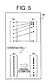
- the relationship between the 125 input color data sets Rn and the 125 output color data sets Xn obtained by measurement is not linear, as indicated in the upper part of the rectangular block in Fig. 5, due to the color production by the color display device 14 according to the additive color mixing system.
- the device 42 operates to effect an inverse estimation to obtain a large number of input color data sets Rn corresponding to the thus obtained large number of output color data sets Xn having the predetermined interval.
- the high-resolution input-output relationship Xn f disp (Rn) of the color display device 14 is obtained by the device 42.
- the device 42 generates a second number of output color data sets Xn by interpolation of the 125 output color data sets Xn.
- the second number is considerably larger than the first number.
- the output color data sets Xn are considered as external color data sets representative of colors of a color image as reproduced on the recording medium 22 and as viewed by a observer, while the input color data Rn are considered as internal color data sets which are processed within the color display device 14 to reproduce a color image, namely, which represent a color image to be reproduced.
- This first color data correlation generating step is performed each time the device 46 receives the image signal SG1 from the color scanner 10.
- This second color data correlation generating step is performed each time the device 52 receives the image signal SG2 from the first data converting device 48.
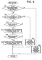
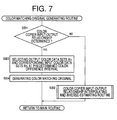
- Figs. 6-12 there will be described the operations of the computer 18, which is adapted to execute a main routine illustrated in the flow chart of Fig. 6, which includes step SM2 for executing a color matching original generating routine illustrated in the flow chart of Fig. 7, and step SM4 for executing a color matching preparation routine illustrated in the flow chart of Fig. 9.
- the color matching original generating routine of Fig. 7 includes step SB2 for executing a color copier input-output relationship interpolating and inverse-estimating routine illustrated in the flow chart of Fig. 8.
- the color matching preparation routine of Fig. 9 includes step SD2 for executing a color scanner input-output relationship interpolating and inverse-estimating routine illustrated in the flow chart of Fig.
- step SD4 for executing a color display input-output relationship interpolating and inverse-estimating routine illustrated in the flow chart of Fig. 12, and step SD6 for executing the color copier input-output relationship interpolating and inverse-estimating routine of Fig. 8.
- step SM1 for determining whether a COLOR MATCHING ORIGINAL GENERATING MODE is presently selected. This determination is effected based on a signal received from the keyboard 16. If an affirmative decision (YES) is obtained in step SM1, the control flow goes to step SM2 in which the color matching original generating routine of Fig. 7 is executed by the color matching original generating device 34.
- the color copier 20 is operated to reproduce 125 colors on the recording medium 22, and the reproduced colors are measured by a color measuring device in the form of the spectrophotometer 32.
- Each output color data set Xn consists of the tristimulus values X, Y and Z in the CIE chromaticity coordinate system.
- a non-linear relationship between the 125 input color data sets Rn and the corresponding 125 output color data sets Xn is determined.
- Step SC1 is followed by step SC2 in which a larger number of output color data sets Xn are obtained by interpolating the tristimulus values x, Y and Z of the 125 output color data sets Xn such that the thus obtained output color data sets have a predetermined color difference interval.
- This larger number (second number) is a sum of the number (first number) of the original 125 output color data sets Xn, and the number of output color data obtained by the interpolation, as indicated by "o" marks in Fig. 3.
- the second number may be the maximum number of input color data sets Rn that can be used by the color copier 20, or may be equal to the number of output data sets Xn large enough to assure a practically satisfactory high degree of density of the picture elements or color image resolution.
- the 125 input color data sets Rn and the corresponding output color data sets Xn obtained by measurement are indicated by five free curves or approximating curves such as spline curves and Bezier curves corresponding to respective five different G values, in each of five two-dimensional R-X, R-Y and R-Z coordinate systems, which correspond to respective five different B values.
- the first number (125) of output color data sets Xn are interpolated to obtain the second number of output color data sets Xn.
- a distance between two adjacent ones of the five X values which are defined by points of intersection of the five curves and the X axis in the R-X coordinate system is interpolated to obtain equally spaced-apart points of interpolation along the X axis, for each of the five B values.
- a distance between two adjacent ones of the five Y values which are defined by points of intersection of the five curves and the Y axis in the R-Y coordinate system is interpolated to obtain equally spaced-apart points of interpolation along the Y axis, for each of the five B values.
- a distance between two adjacent ones of the five Z values which are defined by points of intersection of the five curves and the Z axis in the R-Z coordinate system is interpolated to obtain equally spaced-apart points of interpolation along the Z axis, for each of the five B values.
- step SC3 the control flow goes to step SC3 in which the second number of input color data sets Rn corresponding to the second number of output color data sets Xn obtained in step SC2 are obtained by inverse estimation utilizing the approximating curves indicated above.
- step SC2 the relationships represented by the approximating curves shown in Fig. 10 are used to obtain the second number of output color data sets Xn by interpolation as indicated by the "o" marks in Fig. 3.
- an affirmative decision YES
- the selected output color data sets Xn must have a predetermined constant color difference interval.
- the device 34 determines the input color data sets Rn corresponding to the selected output color data sets Xn.
- the device 34 applies the determined input color data sets Rn to the color copier 20, so that a color image is reproduced on the recording medium 22, as the color matching original 36 which bears colors as represented by the output color data sets Xn.
- step SM3 if a negative decision (NO) is obtained in step SM1.
- step SM3 a determination as to whether a COLOR MATCHING PREPARATION mode is presented selected is effected based on a signal received from the keyboard 16. If an affirmative decision (YES) is obtained in step SM3, the control flow goes to step SM4 in which the color matching preparation routine of Fig. 9 is executed.
- the device 38 then activates the color scanner 10 to read the color matching original 36, and stores the output color data sets Rn which correspond to the 125 input color data sets Xn and which are generated by the color scanner 10.
- These output color data sets Rn constitute the imag signal SG1.
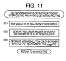
- the non-linear relationship betwen the 125 input color data sets Xn and the corresponding output color data sets Rn is obtained in step SE1.
- Step SE1 is followed by step SE2 similar to step SC2, in which a larger number of output color data sets Rn are obtained by interpolating the R, G and B values of the 125 output color data sets Rn such that the thus obtained output color data sets have a predetermined color difference interval.
- This larger number (second number) may be the maximum number of output color data sets Rn that can be outputted by the color scanner 10 and that can be used by the color display device 14 and the color copier 20, or may be equal to the number of output data sets Rn of the color scanner 10, which is large enough to assure a practically satisfactory high degree of density of the picture elements or color image resolution.
- step SE3 the control flow goes to step SE3 in which the second number of output color data sets Rn corresponding to the second number of input color data sets Xn obtained in step SE2 are obtained by inverse estimation utilizing the approximating curves indicating the relationships between the 125 input color data sets Xn and the 125 output color data sets Rn.
- step SE2 the relationships represented by the approximating curves are used to obtain the second number of output color data sets Xn by interpolation as indicated by the "o" marks in Fig. 4.
- step SD4 the color display input-output relationship interpolating and intervese-estimating routine of Fig. 12 is executed.
- Steps SF1-SF3 of this routine of Fig. 12 are similar to steps SC1-SC3 of the routine of Fig. 8.
- the color display device 14 is operated to reproduce 125 colors on its display screen, and the reproduced colors are measured by the spectrophotometer 44 (color measuring device).
- Each output color data set Xn consists of the tristimulus values X, Y, Z in the CIE chromaticity coordinate system.
- a non-linear relationship between the 125 input color data sets Rn and the corresponding 125 output colr data sets Xn is determined.
- Step SF1 is followed by step SF2 in which a larger number of output color data sets Xn are obtained by interpolating the tristimulus values x, Y and Y of the 125 output color data sets Xn such that the thus obtained output color data sets have a predetermined color difference interval, as in step SC2 of Fig. 8.
- This larger number (second number) is a sum of the number (first number) of the original 125 output color data sets Xn, and the number of output color data obtained by the interpolation, as indicated by "o" marks in Fig. 5.
- the second number may be the maximum number of input color data sets Rn that can be used by the color display device 14, or may be equal to the number of output color data sets Xn which is large enough to assure a paractically satisfactory high degree of density of the picture elements or color image resolution.
- step SF3 the second number of input color data sets Rn corresponding to the second number of output color data sets Xn obtained in step SF2 are obtained by inverse estimation utilizing the approximating curves indicated above.
- step SF2 the relationships represented by the approximating curves are used to obtain the second number of output color data sets Xn by interpolation as indicated by the "o" marks in Fig. 5.
- step SM5 if the negative decision (NO) is obtained in both of steps SM1 and SM3.
- the colors of the color image reproduced on the screen of the color display device 14 according to the image signal SG2 are matched with the colors of the color image on the recording medium 22, which color image has been read by the color scanner 10. Further, the colors of the color image reproduced on the recording medium 22 by the color copier 20 according to the image signal SG3 are matched with the colors of the color image on the original 12 read by the color scanner 10, and with the colors of the color image reproduced on the color display device 14 according to the image signal SG2.
- An experimentation conducted by the present inventor revealed that the present color matching method makes it possible to achieve accurate color matching with a maximum color difference ⁇ E* ab as small as about 2, contrary to the conventional color matching with a maximum color difference ⁇ E* ab as large as about 20.
- the color matching method in the present embodiment described above includes the color scanner input-output relationship interpolating and inverse-estimating step (SD2) wherein the predetermined first number of (e.g., 125) input color data sets (external color data) Xn having a predetermined color difference interval are determined, and the original color image having colors as represented by those input color data sets Xn is read by the color scanner 10 (color image input device), so that the predetermined number of output color data sets (internal color data) Rn generated by the color scanner 10 are obtained in relation to the input color data sets Xn.
- SD2 color scanner input-output relationship interpolating and inverse-estimating step
- the predetermined second number of output color data sets Rn are obtained by interpolating the first number of output color data sets Rn, and the predetermined second number of input color data sets Xn corresponding to the predetermined second number of output color data sets Rn are obtained by inverse estimation.
- the high-resolution input-output relationship Rn f imag (Xn) between the second number of the output color data sets Rn and the second number of the input color data sets Xn.
- the present method further includes the color display input-output relationship interpolating and inverse-estimating step (SD4) wherein the predetermined first number of (e.g., 125) input color data sets (internal color data) Rn having a predetermined color difference interval are determined, and these determined input color data sets Rn are applied to the color display device 14 (color image output device), so that the predetermined number of output color data sets (external color data) Xn representing the colors reproduced on the color display device 14 are obtained in relation to the input color data sets Rn.
- SD4 color display input-output relationship interpolating and inverse-estimating step
- the predetermined second number of output color data sets Xn are obtained by interpolating the first number of output color data sets Xn, and the predetermined second number of input color data sets Rn corresponding to the predetermined second number of output color data sets Xn are obtained by inverse estimation.
- the high-resolution input-output relationship Xn f disp (Rn) between the second number of the output color data sets Xn and the second number of the input color data sets Rn.
- the colors of the original color image as read by the color scanner 10 can be suitably matched with the colors of the color image as reproduced on the screen of the color display device 14 according to the input color data sets Rn(SG2) which are obtained by conversion from the output color data sets Rn(SG1) generated by the color scanner 10.
- This conversion makes it possible to suitably match the colors as reproduced on the screen of the color display device 14 with the colors on the original 12 as read by the color scanner 10.
- the color matching method in the present embodiment described above further includes the color display input-output relationship interpolating and inverse-estimating step (SD4) wherein the predetermined first number of (e.g., 125) input color data sets (internal color data) Rn having a predetermined color difference interval are determined, and the thus determined input color data sets Rn are applied to the color display device 14, to obtain the corresponding output color data sets (external color data) Xn representing the colors as displayed on the color display device 14. Then, the predetermined second number of output color data sets Xn are obtained by interpolating the first number of output color data sets Xn, and the predetermined second number of input color data sets Rn corresponding to the predetermined second number of output color data sets Xn are obtained by inverse estimation.
- the high-resolution input-output relationship Xn f disp (Rn) between the second number of the output color data sets Xn and the second number of the input color data sets Rn.
- the present method further includes the color copier input-output relationship interpolating and inverse-estimating step (SD6) wherein the predetermined first number of (e.g., 125) input color data sets (internal color data) Rn having a predetermined color difference interval are determined, and these determined input color data sets Rn are applied to the color copier 20 (color image output device), so that the predetermined number of output color data sets (external color data) Xn representing the colors reproduced by the color copier 20 are obtained in relation to the input color data sets Rn.
- SD6 color copier input-output relationship interpolating and inverse-estimating step
- the predetermined second number of output color data sets Xn are obtained by interpolating the first number of output color data sets Xn, and the predetermined second number of input color data sets Rn corresponding to the predetermined second number of output color data sets Xn are obtained by inverse estimation.
- the high-resolution input-output relationship Xn f copy (Rn) between the second number of the output color data sets Xn and the second number of the input color data sets Rn.
- the colors of the color image as reproduced on the screen of the color display device 14 can be suitably matched with the colors of the color image as reproduced by the color copier 20 according to the input color data sets Rn(SG3) which are obtained by conversion from the output color data sets Rn(SG2) which are used for the color display device 14.
- This conversion makes it possible to suitably match the colors as reproduced on the screen of the color display device 14 with the colors as reproduced on the recording medium 20 by the color copier 20.
- the external color data of the first image processing device and the external color data of the second image processing device can be made consistent or matched with each other.
- the external color data (Xn) represent the colors of color images as reproduced by those color image output devices 14, 20.
- the external color data (Xn) represent the colors of a color image on the original 12 as read by the color scanner 10 as the color image input device 10.
- the output color data sets Rn, Xn of those high-resolution relationships obtained by interpolation and inverse estimation have the predetermined constant color difference interval
- the output color data sets Rn, Xn obtained by interpolation in steps SE2, SF2 and SC2 need not have a completely constant color difference interval.
- the color difference between the adjacent output color data sets may more or less differ from the color difference between the other adjacent output color data sets, provided the color difference interval is almost constant, permitting a satisfactory degree of accuracy of the color matching between the input color data sets Xn of the color scanner 10 and the output color data sets Xn of the color display device 14 or color copier 20, and between the output color data sets Xn of the color display device 14 and the color copier 20.
- color image input and output apparatus includes the color scanner 10, color display device 14 and color copier 20, one of these three color input and output devices may be eliminated.
- the color copier 20 may be replaced by a second color display device, or the color display device 14 may be replaced by a second color copier.
- the color scanner 10 may be replaced by any other type of color image input device such as a video camera and a digital camera.
- one or both of the color display device 14 and the color copier 20 may be replaced by any other types of color image output device such as a color liquid crystal display, a sublimation type printer, a color laser printer and a silver salt type printer.
- the computer 18 is a stand-alone unit separate from the color scanner 10, color display device 14 and color copier 20, the computer 18 may be built in one of the color scanner 10, color display device 14 and color copier 20.
- the color image input and output apparatus includes the color scanner input-output relationship interpolating and inverse-estimating device 38, color display input-output relationship interpolating and inverse-estimating device 42, color copier input-output relationship interpolating and inverse-estimating device 30, first color data correlation generating device 46 and second color data correlation generating device 50, for effecting color matching among the color scanner 10, color display device 14 and color copier 20.
- color matching original 36 is generated by the color copier 20 in the illustrated embodiment, the color matching original may be generated by any other type of color copying device.
- measuring devices in the form of spectrophotometers 32, 40, 44 are used in the respective color copier input-output relationship interpolating and inverse-estimating step SD6, color scanner input-output relationship interpolating and inverse-estimating step SD2 and color display input-output interpolating and inverse-estimating step SD4, a single measuring device may be used in those steps.
Landscapes
- Engineering & Computer Science (AREA)
- Multimedia (AREA)
- Signal Processing (AREA)
- Facsimile Image Signal Circuits (AREA)
- Color Image Communication Systems (AREA)
- Image Processing (AREA)
- Controls And Circuits For Display Device (AREA)
Applications Claiming Priority (3)
| Application Number | Priority Date | Filing Date | Title |
|---|---|---|---|
| JP310205/97 | 1997-11-12 | ||
| JP31020597 | 1997-11-12 | ||
| JP31020597A JP3223867B2 (ja) | 1997-11-12 | 1997-11-12 | 表示色の色合わせ方法 |
Publications (3)
| Publication Number | Publication Date |
|---|---|
| EP0917353A2 true EP0917353A2 (de) | 1999-05-19 |
| EP0917353A3 EP0917353A3 (de) | 2000-03-29 |
| EP0917353B1 EP0917353B1 (de) | 2006-01-11 |
Family
ID=18002460
Family Applications (1)
| Application Number | Title | Priority Date | Filing Date |
|---|---|---|---|
| EP98121422A Expired - Lifetime EP0917353B1 (de) | 1997-11-12 | 1998-11-11 | Verfahren zur Farbabstimmung von Farbbildverarbeitungsvorrichtungen mit Interpolation einer relativ kleinen Anzahl von Farbdatengruppen |
Country Status (6)
| Country | Link |
|---|---|
| US (1) | US6522338B1 (de) |
| EP (1) | EP0917353B1 (de) |
| JP (1) | JP3223867B2 (de) |
| KR (1) | KR100296765B1 (de) |
| CN (1) | CN1150747C (de) |
| DE (1) | DE69833156T2 (de) |
Families Citing this family (8)
| Publication number | Priority date | Publication date | Assignee | Title |
|---|---|---|---|---|
| GB2363020B (en) * | 2000-04-07 | 2004-08-18 | Discreet Logic Inc | Processing image data |
| JP2002232908A (ja) * | 2000-11-28 | 2002-08-16 | Monolith Co Ltd | 画像補間方法および装置 |
| IL162831A0 (en) * | 2002-01-07 | 2005-11-20 | Genoa Technologies Ltd | Electronic color display for soft proofing |
| US20060041609A1 (en) * | 2004-08-20 | 2006-02-23 | Pellar Ronald J | System and method for multi-dimensional lookup table interpolation |
| JP4380638B2 (ja) | 2006-01-31 | 2009-12-09 | トヨタ自動車株式会社 | 色再現方法 |
| KR101134665B1 (ko) * | 2007-10-15 | 2012-04-09 | 니폰덴신뎅와 가부시키가이샤 | 화상 생성 방법, 장치 및 그 프로그램과 프로그램을 기록한 기록매체 |
| CN111524111B (zh) * | 2020-04-17 | 2023-06-16 | 北京古今盛世文化传播有限公司 | 基于艺术作品的打印处理方法及装置 |
| JP2024040027A (ja) * | 2022-09-12 | 2024-03-25 | 富士フイルムビジネスイノベーション株式会社 | 色調整装置及び色調整プログラム |
Family Cites Families (3)
| Publication number | Priority date | Publication date | Assignee | Title |
|---|---|---|---|---|
| DE69424321T2 (de) * | 1993-08-06 | 2000-10-19 | Toyota Jidosha K.K., Toyota | Verfahren zur Selektion der Farbe eines Lackes |
| US5809213A (en) * | 1996-02-23 | 1998-09-15 | Seiko Epson Corporation | Automatic color calibration of a color reproduction system |
| US6088038A (en) * | 1997-07-03 | 2000-07-11 | Minnesota Mining And Manufacturing Company | Arrangement for mapping colors between imaging systems and method therefor |
-
1997
- 1997-11-12 JP JP31020597A patent/JP3223867B2/ja not_active Expired - Fee Related
-
1998
- 1998-11-11 EP EP98121422A patent/EP0917353B1/de not_active Expired - Lifetime
- 1998-11-11 DE DE69833156T patent/DE69833156T2/de not_active Expired - Lifetime
- 1998-11-11 CN CNB981231470A patent/CN1150747C/zh not_active Expired - Fee Related
- 1998-11-11 KR KR1019980048144A patent/KR100296765B1/ko not_active Expired - Fee Related
- 1998-11-12 US US09/190,848 patent/US6522338B1/en not_active Expired - Fee Related
Also Published As
| Publication number | Publication date |
|---|---|
| KR19990045187A (ko) | 1999-06-25 |
| CN1219072A (zh) | 1999-06-09 |
| JPH11146217A (ja) | 1999-05-28 |
| EP0917353A3 (de) | 2000-03-29 |
| JP3223867B2 (ja) | 2001-10-29 |
| US6522338B1 (en) | 2003-02-18 |
| DE69833156D1 (de) | 2006-04-06 |
| KR100296765B1 (ko) | 2001-08-07 |
| EP0917353B1 (de) | 2006-01-11 |
| CN1150747C (zh) | 2004-05-19 |
| DE69833156T2 (de) | 2006-08-17 |
Similar Documents
| Publication | Publication Date | Title |
|---|---|---|
| US5363318A (en) | Method and apparatus for adaptive color characterization and calibration | |
| US5786908A (en) | Method and apparatus for converting image color values from a first to a second color space | |
| US5692071A (en) | Color image processing method and apparatus for generating device-dependent color signals | |
| US6181445B1 (en) | Device-independent and medium-independent color matching between an input device and an output device | |
| US5481655A (en) | System for matching a picture on a monitor to a printed picture | |
| US5267030A (en) | Method and associated apparatus for forming image data metrics which achieve media compatibility for subsequent imaging application | |
| US5420979A (en) | Method and apparatus for using composite transforms to form intermediary image data metrics which achieve device/media compatibility for subsequent imaging applications | |
| US6204939B1 (en) | Color matching accuracy inside and outside the gamut | |
| US5717783A (en) | Color correction apparatus and method and color image processing system including the same | |
| JPH0522227B2 (de) | ||
| JPH0856289A (ja) | カラー出力装置によりカラー画像を再現するための方法 | |
| EP0587128A1 (de) | Bildverarbeitungssystem und Verfahren zur originalgetreuen Wiedergabe der Farben von Objekten auf Negativfilm | |
| JP3403157B2 (ja) | 画像処理装置およびその方法 | |
| US6151135A (en) | Method and apparatus for color reproduction | |
| JP2001189875A (ja) | 画像捕捉の非線形性を補償するためのプロファイルの構成 | |
| US7142710B2 (en) | Color image processing method and color image processing apparatus | |
| JPH10271344A (ja) | カラー画像処理装置 | |
| EP0917353B1 (de) | Verfahren zur Farbabstimmung von Farbbildverarbeitungsvorrichtungen mit Interpolation einer relativ kleinen Anzahl von Farbdatengruppen | |
| US6327052B1 (en) | Color data inversion and reconversion | |
| US6160635A (en) | Color conversion method using ordered color signal interpolation | |
| EP0664015B1 (de) | Verfahren und vorrichtung zur transformation von bilddaten von einem ersten in einen zweiten farbraum | |
| EP0703700A2 (de) | Verfahren und Vorrichtung zur Bildvoraussage | |
| Kanamori et al. | Fast color processor with programmable interpolation by small memory (PRISM) | |
| JPH0795427A (ja) | 画像処理方法及び装置 | |
| JPH07288703A (ja) | カラー画像出力装置 |
Legal Events
| Date | Code | Title | Description |
|---|---|---|---|
| PUAI | Public reference made under article 153(3) epc to a published international application that has entered the european phase |
Free format text: ORIGINAL CODE: 0009012 |
|
| 17P | Request for examination filed |
Effective date: 19981111 |
|
| AK | Designated contracting states |
Kind code of ref document: A2 Designated state(s): DE FR GB |
|
| AX | Request for extension of the european patent |
Free format text: AL;LT;LV;MK;RO;SI |
|
| PUAL | Search report despatched |
Free format text: ORIGINAL CODE: 0009013 |
|
| AK | Designated contracting states |
Kind code of ref document: A3 Designated state(s): AT BE CH CY DE DK ES FI FR GB GR IE IT LI LU MC NL PT SE |
|
| AX | Request for extension of the european patent |
Free format text: AL;LT;LV;MK;RO;SI |
|
| AKX | Designation fees paid |
Free format text: DE FR GB |
|
| GRAP | Despatch of communication of intention to grant a patent |
Free format text: ORIGINAL CODE: EPIDOSNIGR1 |
|
| GRAS | Grant fee paid |
Free format text: ORIGINAL CODE: EPIDOSNIGR3 |
|
| GRAA | (expected) grant |
Free format text: ORIGINAL CODE: 0009210 |
|
| AK | Designated contracting states |
Kind code of ref document: B1 Designated state(s): DE FR GB |
|
| REF | Corresponds to: |
Ref document number: 69833156 Country of ref document: DE Date of ref document: 20060406 Kind code of ref document: P |
|
| ET | Fr: translation filed | ||
| PLBE | No opposition filed within time limit |
Free format text: ORIGINAL CODE: 0009261 |
|
| STAA | Information on the status of an ep patent application or granted ep patent |
Free format text: STATUS: NO OPPOSITION FILED WITHIN TIME LIMIT |
|
| 26N | No opposition filed |
Effective date: 20061012 |
|
| REG | Reference to a national code |
Ref country code: GB Ref legal event code: 746 Effective date: 20091103 |
|
| PGFP | Annual fee paid to national office [announced via postgrant information from national office to epo] |
Ref country code: DE Payment date: 20091105 Year of fee payment: 12 |
|
| PGFP | Annual fee paid to national office [announced via postgrant information from national office to epo] |
Ref country code: GB Payment date: 20091111 Year of fee payment: 12 Ref country code: FR Payment date: 20091123 Year of fee payment: 12 |
|
| GBPC | Gb: european patent ceased through non-payment of renewal fee |
Effective date: 20101111 |
|
| REG | Reference to a national code |
Ref country code: DE Ref legal event code: R119 Ref document number: 69833156 Country of ref document: DE Effective date: 20110601 Ref country code: DE Ref legal event code: R119 Ref document number: 69833156 Country of ref document: DE Effective date: 20110531 |
|
| REG | Reference to a national code |
Ref country code: FR Ref legal event code: ST Effective date: 20110801 |
|
| PG25 | Lapsed in a contracting state [announced via postgrant information from national office to epo] |
Ref country code: DE Free format text: LAPSE BECAUSE OF NON-PAYMENT OF DUE FEES Effective date: 20110531 |
|
| PG25 | Lapsed in a contracting state [announced via postgrant information from national office to epo] |
Ref country code: FR Free format text: LAPSE BECAUSE OF NON-PAYMENT OF DUE FEES Effective date: 20101130 |
|
| PG25 | Lapsed in a contracting state [announced via postgrant information from national office to epo] |
Ref country code: GB Free format text: LAPSE BECAUSE OF NON-PAYMENT OF DUE FEES Effective date: 20101111 |