EP0917405A2 - Dispositif pour prévenir la condensation sur un détecteur pour four à micro-ondes - Google Patents
Dispositif pour prévenir la condensation sur un détecteur pour four à micro-ondes Download PDFInfo
- Publication number
- EP0917405A2 EP0917405A2 EP98309353A EP98309353A EP0917405A2 EP 0917405 A2 EP0917405 A2 EP 0917405A2 EP 98309353 A EP98309353 A EP 98309353A EP 98309353 A EP98309353 A EP 98309353A EP 0917405 A2 EP0917405 A2 EP 0917405A2
- Authority
- EP
- European Patent Office
- Prior art keywords
- sensor
- prevention apparatus
- microwave oven
- wet prevention
- wet
- Prior art date
- Legal status (The legal status is an assumption and is not a legal conclusion. Google has not performed a legal analysis and makes no representation as to the accuracy of the status listed.)
- Granted
Links
- 230000002265 prevention Effects 0.000 title claims abstract description 61
- 230000000903 blocking effect Effects 0.000 claims abstract description 29
- 238000010411 cooking Methods 0.000 claims abstract description 23
- 238000002955 isolation Methods 0.000 claims abstract description 7
- 238000012986 modification Methods 0.000 description 3
- 230000004048 modification Effects 0.000 description 3
- 238000004519 manufacturing process Methods 0.000 description 2
- 230000005540 biological transmission Effects 0.000 description 1
- 238000010276 construction Methods 0.000 description 1
- 230000000694 effects Effects 0.000 description 1
- 230000005484 gravity Effects 0.000 description 1
- 238000000034 method Methods 0.000 description 1
Images


Classifications
-
- F—MECHANICAL ENGINEERING; LIGHTING; HEATING; WEAPONS; BLASTING
- F24—HEATING; RANGES; VENTILATING
- F24C—DOMESTIC STOVES OR RANGES ; DETAILS OF DOMESTIC STOVES OR RANGES, OF GENERAL APPLICATION
- F24C7/00—Stoves or ranges heated by electric energy
- F24C7/02—Stoves or ranges heated by electric energy using microwaves
-
- H—ELECTRICITY
- H05—ELECTRIC TECHNIQUES NOT OTHERWISE PROVIDED FOR
- H05B—ELECTRIC HEATING; ELECTRIC LIGHT SOURCES NOT OTHERWISE PROVIDED FOR; CIRCUIT ARRANGEMENTS FOR ELECTRIC LIGHT SOURCES, IN GENERAL
- H05B6/00—Heating by electric, magnetic or electromagnetic fields
- H05B6/64—Heating using microwaves
- H05B6/642—Cooling of the microwave components and related air circulation systems
-
- H—ELECTRICITY
- H05—ELECTRIC TECHNIQUES NOT OTHERWISE PROVIDED FOR
- H05B—ELECTRIC HEATING; ELECTRIC LIGHT SOURCES NOT OTHERWISE PROVIDED FOR; CIRCUIT ARRANGEMENTS FOR ELECTRIC LIGHT SOURCES, IN GENERAL
- H05B6/00—Heating by electric, magnetic or electromagnetic fields
- H05B6/64—Heating using microwaves
- H05B6/6447—Method of operation or details of the microwave heating apparatus related to the use of detectors or sensors
Definitions
- the present invention relates to a wet prevention apparatus for a sensor of a microwave oven, and more particularly, to a wet prevention apparatus for a sensor of a microwave oven, which prevents wet from occurring in a sensor for use in a microwave oven without a separate driving gear.
- various sensors are used in a microwave oven to obtain various cooking information.
- the sensor there is an infrared ray sensor for sensing a temperature inside a cooking chamber.
- the infrared ray sensor is mounted in a machine chamber, where various parts such as a magnetron and a fan are mounted, and senses a temperature inside the cooking chamber through a sensor hole formed at one sidewall of the cooking chamber. Vapor which occurs in the cooking chamber is entered into the machine chamber through the sensor hole, and wet occurs in the sensor due to the entered vapor. Accordingly, it is necessary to prevent wet from occurring in the sensor.
- a microwave oven body 1 includes a cooking chamber 2 and a machine chamber 4.
- the cooking chamber 2 and the machine chamber 4 are isolated from each other by means of an isolation wall 1a.
- a sensor 12 which senses a temperature of the cooking chamber 2 is mounted in the machine chamber 4.
- a sensor bracket 5 is fixed to a predetermined position of the body 1.
- a sensor case 10 is rotatably is mounted in the bracket 5.
- the sensor 12 is mounted within the sensor case 10.
- a driving portion which rotates the sensor case 10 is mounted at one side of the sensor bracket 5.
- a step motor 13 is generally used as the driving portion.
- the step motor 13 transfers rotative force to the sensor case 10 through a power transmission means such as a gear 14.
- the sensor case 10 having the sensor 12 therein is arranged in such a manner that a filter 11 is placed toward a sensor hole 3 formed at the isolation wall 1a.
- step motor 13 is driven to rotate the sensor case 10 a predetermined angle, so that the filter 11 is not placed toward the sensor hole 3 to prevent wet from occurring in the filter 11 due to vapor entered from the cooking chamber 2 through the sensor hole 3.
- the background art wet prevention apparatus for a sensor has a structure which prevents wet from occurring by rotating the sensor case 10, a driving portion, i.e., a step motor 13 for rotating the sensor case 10, and the gear 14 are required.
- a driving portion i.e., a step motor 13 for rotating the sensor case 10
- the gear 14 are required. This results in complicated structure, increases the number of parts, and complicates assembly process. As a result, the manufacturing cost is also increased.
- step motor 13 should be controlled depending on cooking course, a separate algorithm for controlling the step motor is required.
- step motor 13 the gear 14 and the sensor case 10 are all driven, it is likely that the driving portion is wrong.
- Preferred embodiments of the present invention are directed to a wet prevention apparatus for a sensor of a microwave oven that substantially obviates one or more of the problems due to limitations and disadvantages of the background art.
- a microwave oven including a cooking chamber, and a machine chamber isolated from the cooking chamber by an isolation wall having a sensor hall, wherein a sensor case having a sensor therein and a fan are mounted in the machine chamber, a wet prevention apparatus for a sensor of a microwave oven comprising an air receiving member for moving by air flow which occurs when driving the fan, and a blocking member linked to the operation of the air receiving member, for selectively blocking the sensor hole.
- the air receiving member may have a plate shape and may be approximately mounted in parallel with the fan, and the blocking member may have a plate shape and may be approximately mounted in parallel with the isolation wall.
- the wet prevention apparatus may be rotatably mounted in a predetermined position of a suction guide which guides air flow generated by the fan.
- the wet prevention apparatus may rotatably be mounted in the sensor case directly.
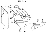
- Fig. 3 is an exploded perspective view illustrating a wet prevention apparatus for a sensor of a microwave oven according to a first embodiment of the present invention.
- the wet prevention apparatus for a sensor of a microwave oven according to the first embodiment of the present invention will now be described with reference to Fig. 3.
- the same elements as the background art have the same reference numerals as those of the background art and their description is omitted.
- a sensor bracket 5 is fixed to a predetermined position of a microwave oven body.
- a sensor case 10 is mounted in the sensor bracket 5.
- a wet prevention apparatus 100 is rotatably mounted in a suction guide 15 which guides air flow generated by a fan.
- the wet prevention apparatus 100 will be described below.
- the wet prevention apparatus 100 includes an air receiving member 22 for moving by air flow generated by the fan, and a blocking member 20 linked to the operation of the air receiving member 22, for selectively blocking a sensor hole 3.
- the air receiving member 22 has a plate shape in such a manner that an area which contacts with air is large. Also, it is preferable that the blocking member 20 has an area capable of blocking the sensor hole 3. It is more preferable that the blocking member 20 has a plate shape having a large area to facilitate blocking of the sensor hole 3.
- the air receiving member 22 is mounted to allow its surface having a large area to be placed toward a fan 9.
- the blocking member 20 is mounted to allow its surface having a large area to be placed toward the sensor hole 3. Accordingly, the air receiving member 22 and the blocking member 20 are approximately orthogonal each other.
- the center of gravity of the wet prevention apparatus 100 is placed toward the air receiving member 22.
- the blocking member 20 is placed to block the sensor hole 3 by tare of the wet prevention apparatus 100 when the fan stops its operation. While the blocking member 20 rotates to open the sensor hole 3 when the fan is driven.
- a hinge shaft 16 is formed at one side of the suction guide 15. A free end of the hinge shaft 16 is cut away, so that a projection 17 is formed up and down. A hollow portion 25 is formed between the air receiving member 22 and the blocking member 20. The hinge shaft 16 is rotatably inserted into the hollow portion 25.
- the projection 17 prevents the wet prevention apparatus 100 from being detached.
- the blocking member 20 should be placed between the sensor hole 3 and the sensor to selectively block the sensor hole 3 depending on the operation of the fan 9.
- the wet prevention apparatus 100 is placed in a predetermined position by tare. In other words, the wet prevention apparatus 100 is placed in such a manner that the blocking member 20 blocks the sensor hole 3.
- the air receiving member 22 rotates clockwise on the drawing by air generated by rotation of the fan 9.
- the blocking member 20 linked to the operation of the air receiving member 22 also rotates and the sensor hole 3 is open. Accordingly, the sensor can sense a temperature inside the cooking chamber.
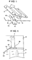
- a rotation ring 44 may be formed in the suction guide 15 and a hole 45 into which the rotation ring 44 is inserted may be formed in the wet prevention apparatus 100.
- the wet prevention apparatus 100 rotates around the rotation ring 44 to selectively block the sensor hole.
- a projection 48 may be formed in the suction guide 15 and a hole 49 into which the projection 48 is inserted may be formed in the wet prevention apparatus 100.
- the operation of the wet prevention apparatus 100 is the same as the aforementioned embodiment.
- the wet prevention apparatus 100 may be mounted in any other proper position.
- the wet prevention apparatus 100 may be mounted in a predetermined position of the body in such a manner that the blocking member 20 is placed between the sensor hole 3 and the sensor if air flow does not occur in the machine chamber.
- the fourth embodiment of the present invention which will be described below is a modified example of the aforementioned embodiments.
- the operation of the fourth embodiment is different from the aforementioned embodiments in that the wet prevention apparatus 100 is incorporated into the sensor case 10.
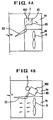
- the wet prevention apparatus 100 for a sensor of a microwave oven according to the fourth embodiment of the present invention will be described with reference to Figs. 7 and 8.
- a sensor case 10 having a sensor therein is incorporated into a sensor bracket 5.
- One end of the wet prevention apparatus 100 is rotatably incorporated into the sensor case 10.
- a rotation center member 34 having a hinge hole 35 therein is formed on a top of the blocking member 20.
- the rotation center member 34 is hinge-coupled to the sensor case 10 to rotate around a hinge shaft 37.
- the blocking member 20 is placed between the sensor hole 3 and the sensor, and the air receiving member 22 is placed to move depending on air flow generated by the fan 9.
- the wet prevention apparatus 100 rotates around the hinge shaft 37.
- the wet prevention apparatus for a sensor of a microwave oven that have been described have the following effects.
- the wet prevention apparatus is operated using air flow generated by rotation of the fan for use in the microwave oven, the structure of the wet prevention apparatus is simple and the manufacturing cost is reduced.
- the driving portion is not wrong, life-span of the microwave oven is extended and energy is also saved.
- a control algorithm for controlling the control means is not required, a control algorithm for use in the microwave oven becomes simple.
Landscapes
- Physics & Mathematics (AREA)
- Electromagnetism (AREA)
- Engineering & Computer Science (AREA)
- Chemical & Material Sciences (AREA)
- Combustion & Propulsion (AREA)
- Mechanical Engineering (AREA)
- General Engineering & Computer Science (AREA)
- Electric Ovens (AREA)
Applications Claiming Priority (2)
| Application Number | Priority Date | Filing Date | Title |
|---|---|---|---|
| KR6024897 | 1997-11-15 | ||
| KR1019970060248A KR100275872B1 (ko) | 1997-11-15 | 1997-11-15 | 전자레인지 센서의 습기방지장치 |
Publications (3)
| Publication Number | Publication Date |
|---|---|
| EP0917405A2 true EP0917405A2 (fr) | 1999-05-19 |
| EP0917405A3 EP0917405A3 (fr) | 2000-04-12 |
| EP0917405B1 EP0917405B1 (fr) | 2006-09-20 |
Family
ID=19524813
Family Applications (1)
| Application Number | Title | Priority Date | Filing Date |
|---|---|---|---|
| EP98309353A Expired - Lifetime EP0917405B1 (fr) | 1997-11-15 | 1998-11-16 | Dispositif pour prévenir la condensation sur un détecteur pour four à micro-ondes |
Country Status (6)
| Country | Link |
|---|---|
| US (1) | US6051824A (fr) |
| EP (1) | EP0917405B1 (fr) |
| JP (2) | JPH11241829A (fr) |
| KR (1) | KR100275872B1 (fr) |
| CN (1) | CN1104597C (fr) |
| DE (1) | DE69835930T2 (fr) |
Families Citing this family (8)
| Publication number | Priority date | Publication date | Assignee | Title |
|---|---|---|---|---|
| US6772752B1 (en) * | 2003-04-10 | 2004-08-10 | Maytag Corporation | Cooling system airflow sensor for a cooking appliance |
| CN101943429B (zh) * | 2009-07-10 | 2014-06-04 | 乐金电子(天津)电器有限公司 | 微波炉的温度传感器结构 |
| WO2011028729A1 (fr) | 2009-09-01 | 2011-03-10 | Manitowoc Foodservice Companies, Llc | Procédé et appareil pour une entrée d'air dans un dispositif de cuisson |
| JP2011125258A (ja) * | 2009-12-17 | 2011-06-30 | Panasonic Corp | 食品加熱調理方法 |
| US20150302569A1 (en) * | 2014-04-22 | 2015-10-22 | General Electric Company | Sensing system for a cooktop appliance with airflow protected sensor |
| JP6637584B2 (ja) * | 2018-12-26 | 2020-01-29 | 日立グローバルライフソリューションズ株式会社 | 加熱調理器 |
| JP6823152B2 (ja) * | 2019-12-20 | 2021-01-27 | 日立グローバルライフソリューションズ株式会社 | 加熱調理器 |
| CN116509204A (zh) * | 2022-01-20 | 2023-08-01 | 广东美的厨房电器制造有限公司 | 烹饪设备 |
Family Cites Families (13)
| Publication number | Priority date | Publication date | Assignee | Title |
|---|---|---|---|---|
| US4308444A (en) * | 1976-03-11 | 1981-12-29 | Sharp Kabushiki Kaisha | Microwave oven with a capability of functioning as an electric heating oven |
| JPS53144044A (en) * | 1977-05-20 | 1978-12-15 | Hitachi Heating Appliance Co Ltd | High frequency heater |
| JPS5813816B2 (ja) * | 1977-07-15 | 1983-03-16 | 松下電器産業株式会社 | 高周波加熱装置 |
| SE426722B (sv) * | 1980-11-14 | 1983-02-07 | Gkn Stenman Ab | Cylinderbehor |
| JPS5929926A (ja) * | 1982-08-10 | 1984-02-17 | Toshiba Corp | 赤外線センサ付調理器 |
| JPS62123228A (ja) * | 1985-11-20 | 1987-06-04 | Sanyo Electric Co Ltd | 調理器 |
| JPS6285807U (fr) * | 1985-11-20 | 1987-06-01 | ||
| JPH01118029A (ja) * | 1987-10-30 | 1989-05-10 | Sanyo Electric Co Ltd | 電子レンジ |
| JPH01263424A (ja) * | 1988-04-14 | 1989-10-19 | Sanyo Electric Co Ltd | 調理器 |
| JPH0334507U (fr) * | 1989-08-11 | 1991-04-04 | ||
| JP2780469B2 (ja) * | 1990-09-11 | 1998-07-30 | 松下電器産業株式会社 | 加熱調理器 |
| JPH08100922A (ja) * | 1994-09-30 | 1996-04-16 | Sanyo Electric Co Ltd | 高周波加熱装置 |
| DE69608500T2 (de) * | 1995-07-07 | 2001-01-18 | Lg Electronics Inc., Seoul/Soul | Einrichtung zur Vermeidung der Fehlfunktion des Sensors in Mikrowellenöfen |
-
1997
- 1997-11-15 KR KR1019970060248A patent/KR100275872B1/ko not_active Expired - Fee Related
-
1998
- 1998-11-12 US US09/189,794 patent/US6051824A/en not_active Expired - Lifetime
- 1998-11-13 JP JP10324283A patent/JPH11241829A/ja active Pending
- 1998-11-15 CN CN98125828A patent/CN1104597C/zh not_active Expired - Fee Related
- 1998-11-16 DE DE69835930T patent/DE69835930T2/de not_active Expired - Fee Related
- 1998-11-16 EP EP98309353A patent/EP0917405B1/fr not_active Expired - Lifetime
-
2002
- 2002-02-25 JP JP2002048602A patent/JP3572296B2/ja not_active Expired - Fee Related
Also Published As
| Publication number | Publication date |
|---|---|
| CN1221868A (zh) | 1999-07-07 |
| KR19990039978A (ko) | 1999-06-05 |
| DE69835930D1 (de) | 2006-11-02 |
| JP2002250518A (ja) | 2002-09-06 |
| JPH11241829A (ja) | 1999-09-07 |
| CN1104597C (zh) | 2003-04-02 |
| EP0917405B1 (fr) | 2006-09-20 |
| JP3572296B2 (ja) | 2004-09-29 |
| EP0917405A3 (fr) | 2000-04-12 |
| KR100275872B1 (ko) | 2001-02-01 |
| DE69835930T2 (de) | 2007-01-04 |
| US6051824A (en) | 2000-04-18 |
Similar Documents
| Publication | Publication Date | Title |
|---|---|---|
| KR100415024B1 (ko) | 드럼식 세탁기 | |
| US6051824A (en) | Wet prevention apparatus for sensor of microwave oven | |
| US20020005406A1 (en) | Microwave oven with infrared detection element | |
| JP2001244064A (ja) | 電子レンジ | |
| US5591113A (en) | Centrifugally assisted centrifuge bowl mount | |
| EP1079665B1 (fr) | Appareil amortisseur pour four à micro-ondes commandant le flux interne d'air | |
| EP1111964B1 (fr) | Dispositif d'amortissement pour four à micro-ondes | |
| KR100558021B1 (ko) | 팬/틸트 돔형 카메라 | |
| KR100399139B1 (ko) | 전자렌지 | |
| US20070006485A1 (en) | Clothes drying machine | |
| US6946632B2 (en) | Cooking apparatus equipped with weight measuring device | |
| KR100377726B1 (ko) | 후드겸용 전자레인지의 벤트그릴장치 | |
| JP3668181B2 (ja) | 電子レンジ | |
| KR20010018756A (ko) | 후드겸용 전자레인지의 벤트그릴장치 | |
| US6403940B2 (en) | Turntable drive mechanism in a cooking oven | |
| KR100224447B1 (ko) | 전자렌지의 히터회전장치 | |
| KR20020087715A (ko) | 차량용 공조장치 | |
| JP2787747B2 (ja) | ガスクロマトグラフ用オーブン | |
| KR20010018767A (ko) | 후드겸용 전자레인지의 벤트그릴장치 | |
| JPH06338386A (ja) | 電子レンジ | |
| KR20010055978A (ko) | 전자렌지 | |
| KR200160252Y1 (ko) | 가전제품의 도아 힌지장치 | |
| JPH06347041A (ja) | 加熱調理器 | |
| KR200254416Y1 (ko) | 차량 공조기용 송풍기 모터의 브라켓 구조 | |
| EP0855298A1 (fr) | Système d'entrainement en rotation avec une structure simplifiée et capable de détection fiable d'une rotation anormale d'un moteur pas à pas |
Legal Events
| Date | Code | Title | Description |
|---|---|---|---|
| PUAI | Public reference made under article 153(3) epc to a published international application that has entered the european phase |
Free format text: ORIGINAL CODE: 0009012 |
|
| 17P | Request for examination filed |
Effective date: 19981201 |
|
| AK | Designated contracting states |
Kind code of ref document: A2 Designated state(s): DE FR GB IT |
|
| AX | Request for extension of the european patent |
Free format text: AL;LT;LV;MK;RO;SI |
|
| PUAL | Search report despatched |
Free format text: ORIGINAL CODE: 0009013 |
|
| AK | Designated contracting states |
Kind code of ref document: A3 Designated state(s): AT BE CH CY DE DK ES FI FR GB GR IE IT LI LU MC NL PT SE |
|
| AX | Request for extension of the european patent |
Free format text: AL;LT;LV;MK;RO;SI |
|
| AKX | Designation fees paid |
Free format text: DE FR GB IT |
|
| GRAP | Despatch of communication of intention to grant a patent |
Free format text: ORIGINAL CODE: EPIDOSNIGR1 |
|
| GRAS | Grant fee paid |
Free format text: ORIGINAL CODE: EPIDOSNIGR3 |
|
| GRAA | (expected) grant |
Free format text: ORIGINAL CODE: 0009210 |
|
| AK | Designated contracting states |
Kind code of ref document: B1 Designated state(s): DE FR GB IT |
|
| PG25 | Lapsed in a contracting state [announced via postgrant information from national office to epo] |
Ref country code: IT Free format text: LAPSE BECAUSE OF FAILURE TO SUBMIT A TRANSLATION OF THE DESCRIPTION OR TO PAY THE FEE WITHIN THE PRESCRIBED TIME-LIMIT;WARNING: LAPSES OF ITALIAN PATENTS WITH EFFECTIVE DATE BEFORE 2007 MAY HAVE OCCURRED AT ANY TIME BEFORE 2007. THE CORRECT EFFECTIVE DATE MAY BE DIFFERENT FROM THE ONE RECORDED. Effective date: 20060920 |
|
| REG | Reference to a national code |
Ref country code: GB Ref legal event code: FG4D |
|
| REF | Corresponds to: |
Ref document number: 69835930 Country of ref document: DE Date of ref document: 20061102 Kind code of ref document: P |
|
| PGFP | Annual fee paid to national office [announced via postgrant information from national office to epo] |
Ref country code: DE Payment date: 20061122 Year of fee payment: 9 |
|
| PGFP | Annual fee paid to national office [announced via postgrant information from national office to epo] |
Ref country code: IT Payment date: 20061130 Year of fee payment: 9 |
|
| ET | Fr: translation filed | ||
| REG | Reference to a national code |
Ref country code: FR Ref legal event code: ST Effective date: 20070731 |
|
| PLBE | No opposition filed within time limit |
Free format text: ORIGINAL CODE: 0009261 |
|
| STAA | Information on the status of an ep patent application or granted ep patent |
Free format text: STATUS: NO OPPOSITION FILED WITHIN TIME LIMIT |
|
| 26N | No opposition filed |
Effective date: 20070621 |
|
| PG25 | Lapsed in a contracting state [announced via postgrant information from national office to epo] |
Ref country code: FR Free format text: LAPSE BECAUSE OF NON-PAYMENT OF DUE FEES Effective date: 20061130 |
|
| PG25 | Lapsed in a contracting state [announced via postgrant information from national office to epo] |
Ref country code: DE Free format text: LAPSE BECAUSE OF NON-PAYMENT OF DUE FEES Effective date: 20080603 |
|
| PG25 | Lapsed in a contracting state [announced via postgrant information from national office to epo] |
Ref country code: IT Free format text: LAPSE BECAUSE OF NON-PAYMENT OF DUE FEES Effective date: 20071116 |
|
| PGFP | Annual fee paid to national office [announced via postgrant information from national office to epo] |
Ref country code: GB Payment date: 20101110 Year of fee payment: 13 |
|
| GBPC | Gb: european patent ceased through non-payment of renewal fee |
Effective date: 20111116 |
|
| PG25 | Lapsed in a contracting state [announced via postgrant information from national office to epo] |
Ref country code: GB Free format text: LAPSE BECAUSE OF NON-PAYMENT OF DUE FEES Effective date: 20111116 |