EP0917709B1 - Sprachkodierung - Google Patents
Sprachkodierung Download PDFInfo
- Publication number
- EP0917709B1 EP0917709B1 EP97933782A EP97933782A EP0917709B1 EP 0917709 B1 EP0917709 B1 EP 0917709B1 EP 97933782 A EP97933782 A EP 97933782A EP 97933782 A EP97933782 A EP 97933782A EP 0917709 B1 EP0917709 B1 EP 0917709B1
- Authority
- EP
- European Patent Office
- Prior art keywords
- phase
- spectrum
- signal
- decoder
- magnitude
- Prior art date
- Legal status (The legal status is an assumption and is not a legal conclusion. Google has not performed a legal analysis and makes no representation as to the accuracy of the status listed.)
- Expired - Lifetime
Links
Images



Classifications
-
- G—PHYSICS
- G10—MUSICAL INSTRUMENTS; ACOUSTICS
- G10L—SPEECH ANALYSIS TECHNIQUES OR SPEECH SYNTHESIS; SPEECH RECOGNITION; SPEECH OR VOICE PROCESSING TECHNIQUES; SPEECH OR AUDIO CODING OR DECODING
- G10L19/00—Speech or audio signals analysis-synthesis techniques for redundancy reduction, e.g. in vocoders; Coding or decoding of speech or audio signals, using source filter models or psychoacoustic analysis
- G10L19/02—Speech or audio signals analysis-synthesis techniques for redundancy reduction, e.g. in vocoders; Coding or decoding of speech or audio signals, using source filter models or psychoacoustic analysis using spectral analysis, e.g. transform vocoders or subband vocoders
Definitions
- the present invention is concerned with speech coding and decoding, and especially with systems in which the coding process fails to convey all or any of the phase information contained in the signal being coded.
- a decoder for speech signals comprising:
- the invention provides a decoder for decoding speech signals comprising information defining the response of a minimum phase synthesis filter and, for synthesis of an excitation signal, magnitude spectral information, the decoder comprising:
- the invention provides a method of coding and decoding speech signals, comprising:
- This first example assumes that a sinusoidal transform coding (STC) technique is employed for the coding and decoding of speech signals.
- STC sinusoidal transform coding
- a coder receives speech samples s(n) in digital form at an input 1; segments of speech of typically 20 ms duration are subject to Fourier analysis in a Fast Fourier Transform unit 2 to determine the short term frequency spectrum of the speech. Specifically it is the amplitudes and frequencies of the peaks in the magnitude spectrum that are of interest, the frequencies being assumed - in the case of voiced speech - to be harmonics of a pitch frequency which is derived by a pitch detector 3.
- the phase spectrum is, in the interests of transmission efficiency, not to be transmitted and a representation of the magnitude spectrum, for transmission to a decoder, is in this example obtained by fitting an envelope to the magnitude spectrum and characterising this envelope by a set of coefficients (e.g. LSP (line spectral pair) coefficients).
- This function is performed by a conversion unit 4 which receives the Fourier coefficients and performs the curve fit and a unit 5 which converts the envelope to LSP coefficients which form the output of the coder.
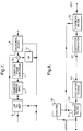
- the corresponding decoder is also shown in Figure 1.
- This receives the envelope information, but, lacking the phase information, has to reconstruct the phase spectrum based on some assumption.
- the assumption used is that the magnitude spectrum represented by the received LSP coefficients is the magnitude spectrum of a minimum-phase transfer function - which amounts to the assumption that the human vocal system can be regarded as a minimum phase filter impulsively excited.
- a unit 6 derives the magnitude spectrum from the received LSP coefficients and a unit 7 calculates the phase spectrum which corresponds to this magnitude spectrum based on the minimum phase assumption.
- a sinusoidal synthesiser 8 From the two spectra a sinusoidal synthesiser 8 generates the sum of a set of sinusoids, harmonic with the pitch frequency, having amplitudes and phases determined by the spectra.
- a synthetic speech signal y(n) is constructed by the sum of sine waves: where A k and ⁇ k represent the amplitude and phase of each sine wave component associated with the frequency track ⁇ k , and N is the number of sinusoids.
- ⁇ k (n) k ⁇ 0 (n) n
- ⁇ k (n) represents the instantaneous relative phase of the harmonics
- ⁇ k (n) represents the instantaneous linear phase component
- ⁇ 0 (n) is the instantaneous fundamental pitch frequency
- a simple example of sinusoidal synthesis is the overlap and add technique.
- a k (n), ⁇ 0 (n) and ⁇ k (n) are updated periodically, and are assumed to be constant for the duration of a short, for example 10 ms, frame.
- the i'th signal frame is thus synthesised as follows: Note that this is essentially an inverse discrete Fourier transform.
- y i (n) W(n)y i -1 (n)+W(n - T)y i (n - T)
- W(n) is an overlap and add window, for example triangular or trapezoidal
- y(n) may be calculated continuously by interpolating the amplitude and phase terms in equation 2.
- the magnitude component A k (n) is often interpolated linearly between updates, whilst a number of techniques have been reported for interpolating the phase component.
- the instantaneous combined phase ( ⁇ k (n) + ⁇ (n)) and pitch frequency ⁇ 0 (n) are specified at each update point.
- the interpolated phase trajectory can then be represented by a cubic polynomial.
- ⁇ k (n) and ⁇ (n) are interpolated separately.
- ⁇ (n) is specified directly at the update points and linearly interpolated, whilst the instantaneous linear phase component ⁇ k (n) is specified at the update points in terms of the pitch frequency ⁇ 0 (n), and only requires a quadratic polynomial interpolation.
- a sinusoidal synthesiser can be generalised as a unit that produces a continuous signal y(n) from periodically updated values of A k (n), ⁇ 0 (n) and ⁇ k (n).
- the number of sinusoids may be fixed or time-varying.
- V(z) minimum phase is a good assumption for the vocal tract transfer function V(z).
- V(z) the vocal tract transfer function
- this may be represented by an all-pole model having the transfer function where ⁇ i are the poles of the transfer function and are directly related to the formant frequencies of the speech, and P is the number of poles.
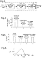
- a unit 31 receives the pitch frequency and calculates values of ⁇ F in accordance with Equation (16) for the relevant values of ⁇ - i.e. harmonics of the pitch frequency for the current frame of speech. These are then added in an adder 32 to the minimum-phase values, prior to the sinusoidal synthesiser 8.
- Equation 16 An alternative to Equation 16, therefore, is to apply at 31 a computed phase equal to the phase of g(t) from Equation (17), as shown in Figure 7.
- the coder transmits details of the filter response, along with information (63) to enable the decoder to construct (64) an excitation signal which is to some extent similar to the residual signal and can be used by the decoder to drive a synthesis filter 65 to produce an output speech signal.
- an excitation signal which is to some extent similar to the residual signal and can be used by the decoder to drive a synthesis filter 65 to produce an output speech signal.
- phase information about the excitation is omitted from the transmission, then a similar situation arises to that described in relation to Figure 2, namely that assumptions need to be made as to the phase spectrum to be employed. Whether phase information for the synthesis filter is included is not an issue since LPC analysis generally produces a minimum phase transfer function in any case so that it is immaterial for the purposes of the present discussion whether the phase response in included in the transmitted filter information (typically a set of filter coefficients) or whether it is computed at the decoder on the basis of a minimum phase assumption.
- the ⁇ 1 is fixed at 0.95 whilst ⁇ 2 is controlled as a function of the pitch period p, in accordance with the following table:
- These values are chosen so that the all-pass transfer function of Equation 15 has
- the calculation unit 91 may be realised by a digital signal processing unit programmed to implement the Equation 16.
- the supposed total transfer function H(z) is the product of G,V and L and thus has, inside the unit circle, P poles at ⁇ i and one zero at a, and, outside the unit circle, two poles at 1/ ⁇ 1 and 1/ ⁇ 2 , as illustrated in Figure 10.
- the effect of the inverse LPC analysis is to produce an inverse filter 61 which flattens the spectrum by means of zeros approximately coinciding with the poles at ⁇ i .
- the filter being a minimum phase filter, cannot produce zeros outside the unit circle at 1/ ⁇ 1 and 2/ ⁇ 2 but instead produces zeros at ⁇ 1 and ⁇ 2 , which tend to flatten the magnitude response, but not the phase response (the filter cannot produce a pole to cancel the zero at ⁇ but as ⁇ 1 usually has a similar value to ⁇ it is common to assume that the ⁇ zero and 1/ ⁇ 1 pole cancel in the magnitude spectrum so that the inverse filter has zeros just at ⁇ i and ⁇ 2 .
- the residual has a phase spectrum represented in the z-plane by two zeros at ⁇ 1 and ⁇ 2 (where the ⁇ 's have values corresponding to the original signal) and poles at 1/ ⁇ 1 and 1/ ⁇ 2 (where the ⁇ 's have values as determined by the LPC analysis).
- This information having been lost, it is approximated by the all-pass filter computation according to equations (15) and (16) which have zeros and poles at these positions.
- Equation 16 This description assumes a phase adjustment determined at all frequencies by Equation 16. However one may alternatively apply Equation 16 only in the lower part of the frequency range - up to a limit which may be fixed or may depend on the nature of the speech, and apply a random phase to higher frequency components.
- the coder has, in conventional manner, a voiced/unvoiced speech detector 92 which causes the decoder to switch, via a switch 93, between the excitation generator 64 and a noise generator whose amplitude is controlled by a gain signal from the coder.
- decoders described have been presented in terms of the decoding of signals coded and transmitted thereto, they may equally well serve to generate speech from coded signals stored and later retrieved - i.e. they could form part of a speech synthesiser.
Landscapes
- Engineering & Computer Science (AREA)
- Physics & Mathematics (AREA)
- Spectroscopy & Molecular Physics (AREA)
- Computational Linguistics (AREA)
- Signal Processing (AREA)
- Health & Medical Sciences (AREA)
- Audiology, Speech & Language Pathology (AREA)
- Human Computer Interaction (AREA)
- Acoustics & Sound (AREA)
- Multimedia (AREA)
- Compression, Expansion, Code Conversion, And Decoders (AREA)
Claims (10)
- Decodierer für Sprachsignale, der umfaßt:eine Einrichtung zum Empfang einer Größenspektrumsinformation zur Synthese eines zeitvariablen Signals,eine Einrichtung zur Berechnung einer Phasenspektrumsinformation aus der Größenspektrumsinformation, die einem Minimalphasenfilter entspricht, die ein Größenspektrum aufweist, das der Größenspektrumsinformation entspricht,eine Einrichtung zur Erzeugung des zeitvariablen Signals aus der Größenspektrumsinformation und der Phasenspektrumsinformation undeine Phaseneinstelleinrichtung, die zur Modifizierung des Phasenspektrums des Signals betrieben werden kann, wobei die Phaseneinstelleinrichtung so betrieben werden kann,daß die Phase in Übereinstimmung mit der Transferfunktion eines Allpaßfilters eingestellt wird, die in einer z-Ebenendarstellung mindestens einen Pol aufweist, der sich außerhalb des Einheitskreises befindet.
- Decodierer zur Decodierung von Sprachsignalen, die Information, die das Ansprechen eines Minimalphasensynthesefilters definiert und Größenspektrumsinformation zur Synthese eines Erregungssignals enthält, wobei der Decodierer aufweist:eine Einrichtung zur Erzeugung eines Erregungssignals aus der Größenspektrumsinformation,ein Synthesefilter, das über die Ansprechinformation gesteuert wird und zur Filterung des Erregungssignals vorgesehen ist, undeine Phaseneinstelleinrichtung zur Abschätzung eines Phaseneinstellsignals zur Modifizierung der Phase des Signals, wobei die Phaseneinstelleinrichtung zur Einstellung der Phase in Übereinstimmung mit der Transferfunktion eines Allpaßfilters betrieben werden kann, die in einer z-Ebenendarstellung mindestens einen Pol aufweist, der sich außerhalb des Einheitskreises befindet.
- Decodierer nach Anspruch 2, bei dem die Einrichtung zur Erzeugung der Erregung zum Empfang des Phaseneinstellsignals so vorgesehen ist, daß eine Erregung erzeugt wird, durch die ein Phasenspektrum bestimmt wird.
- Decodierer nach Anspruch 1 oder 2, bei dem die Phaseneinstelleinrichtung so angeordnet ist, daß sie im Betrieb die Phase des Signals nach seiner Erzeugung modifziert.
- Decodierer nach einem der vorhergehenden Ansprüche, bei dem die Phaseneinstelleinrichtung so betrieben werden kann, daß die Phase in Übereinstimmung mit der Transferfunktion eines Allpaßfilters eingestellt wird, die in einer z-Ebenendarstellung zwei reelle Nullen an den Positionen β1, β2 innerhalb des Einheitskreises und zwei Pole an den Positionen 1/β1, 1/β2 außerhalb des Einheitskreises aufweist.
- Decodierer nach einem der vorhergehenden Ansprüche, bei dem die Position des Pols oder jedes Pols konstant ist.
- Decodierer nach einem der vorhergehenden Ansprüche, bei dem die Einstelleinrichtung so ausgeführt ist, daß sie im Betrieb die Position des Pols oder eines Pols als Funktion der vom Decodierer erhaltenen Information über die Pitchperiode ändert.
- Verfahren zur Codierung und Decodierung von Sprachsignalen, das die folgenden Schritte aufweist:(a) Erzeugung von Signalen, die das Größenspektrum des Sprachsignals darstellen,(b) Empfangen der Signale,(c) Erzeugung eines synthetischen Sprachsignals aus den empfangenen Signalen, das ein Größenspektrum aufweist, das durch die empfangenen Signale bestimmt wird und das ein Phasenspektrum aufweist, das einer Transferfunktion entspricht, die bei graphischer Darstellung in einer z-Ebene mindestens einen Pol außerhalb des Einheitskreises aufweist.
- Verfahren nach Anspruch 8, bei dem das Phasenspektrum des synthetischen Sprachsignals durch Berechnen eines Minimalphasenspektrums aus den empfangenen Signalen und durch Bilden eines zusammengesetzten Phasenspektrums bestimmt wird, das eine Kombination des Minimalphasenspektrums und eines Spektrums darstellt, das dem Pol bzw. den Polen entspricht.
- Verfahren nach Anspruch 8, bei dem in den Signalen solche Signale enthalten sind, die ein Minimalphasensynthesefilter vorgeben und das Phasenspektrum des synthetischen Sprachsignals durch das vorgegebene Synthesefilter und durch ein Phasenspektrum bestimmt wird, das dem Pol bzw. den Polen entspricht.
Priority Applications (1)
| Application Number | Priority Date | Filing Date | Title |
|---|---|---|---|
| EP97933782A EP0917709B1 (de) | 1996-07-30 | 1997-07-28 | Sprachkodierung |
Applications Claiming Priority (4)
| Application Number | Priority Date | Filing Date | Title |
|---|---|---|---|
| EP96305576 | 1996-07-30 | ||
| EP96305576 | 1996-07-30 | ||
| PCT/GB1997/002037 WO1998005029A1 (en) | 1996-07-30 | 1997-07-28 | Speech coding |
| EP97933782A EP0917709B1 (de) | 1996-07-30 | 1997-07-28 | Sprachkodierung |
Publications (2)
| Publication Number | Publication Date |
|---|---|
| EP0917709A1 EP0917709A1 (de) | 1999-05-26 |
| EP0917709B1 true EP0917709B1 (de) | 2000-06-07 |
Family
ID=8225033
Family Applications (1)
| Application Number | Title | Priority Date | Filing Date |
|---|---|---|---|
| EP97933782A Expired - Lifetime EP0917709B1 (de) | 1996-07-30 | 1997-07-28 | Sprachkodierung |
Country Status (6)
| Country | Link |
|---|---|
| US (1) | US6219637B1 (de) |
| EP (1) | EP0917709B1 (de) |
| JP (1) | JP2000515992A (de) |
| AU (1) | AU3702497A (de) |
| DE (1) | DE69702261T2 (de) |
| WO (1) | WO1998005029A1 (de) |
Families Citing this family (16)
| Publication number | Priority date | Publication date | Assignee | Title |
|---|---|---|---|---|
| JP3644263B2 (ja) * | 1998-07-31 | 2005-04-27 | ヤマハ株式会社 | 波形形成装置及び方法 |
| DE69939086D1 (de) | 1998-09-17 | 2008-08-28 | British Telecomm | Audiosignalverarbeitung |
| EP0987680B1 (de) * | 1998-09-17 | 2008-07-16 | BRITISH TELECOMMUNICATIONS public limited company | Audiosignalverarbeitung |
| US6397175B1 (en) * | 1999-07-19 | 2002-05-28 | Qualcomm Incorporated | Method and apparatus for subsampling phase spectrum information |
| US7039581B1 (en) * | 1999-09-22 | 2006-05-02 | Texas Instruments Incorporated | Hybrid speed coding and system |
| US20030048129A1 (en) * | 2001-09-07 | 2003-03-13 | Arthur Sheiman | Time varying filter with zero and/or pole migration |
| US7353168B2 (en) * | 2001-10-03 | 2008-04-01 | Broadcom Corporation | Method and apparatus to eliminate discontinuities in adaptively filtered signals |
| WO2004006225A1 (en) * | 2002-07-08 | 2004-01-15 | Koninklijke Philips Electronics N.V. | Sinusoidal audio coding |
| MXPA05005601A (es) * | 2002-11-29 | 2005-07-26 | Koninklije Philips Electronics | Codificacion de audio. |
| GB2398981B (en) * | 2003-02-27 | 2005-09-14 | Motorola Inc | Speech communication unit and method for synthesising speech therein |
| US8145477B2 (en) * | 2005-12-02 | 2012-03-27 | Sharath Manjunath | Systems, methods, and apparatus for computationally efficient, iterative alignment of speech waveforms |
| JP6011039B2 (ja) * | 2011-06-07 | 2016-10-19 | ヤマハ株式会社 | 音声合成装置および音声合成方法 |
| KR101475894B1 (ko) * | 2013-06-21 | 2014-12-23 | 서울대학교산학협력단 | 장애 음성 개선 방법 및 장치 |
| CN105765655A (zh) | 2013-11-22 | 2016-07-13 | 高通股份有限公司 | 高频带译码中的选择性相位补偿 |
| US10586526B2 (en) * | 2015-12-10 | 2020-03-10 | Kanru HUA | Speech analysis and synthesis method based on harmonic model and source-vocal tract decomposition |
| CN113114160B (zh) * | 2021-05-25 | 2024-04-02 | 东南大学 | 一种基于时变滤波器的线性调频信号降噪方法 |
Family Cites Families (7)
| Publication number | Priority date | Publication date | Assignee | Title |
|---|---|---|---|---|
| US4475227A (en) * | 1982-04-14 | 1984-10-02 | At&T Bell Laboratories | Adaptive prediction |
| JPS6031325A (ja) * | 1983-07-29 | 1985-02-18 | Nec Corp | 予測停止adpcm符号化方式およびその回路 |
| DE3678717D1 (de) * | 1986-04-30 | 1991-05-16 | Ibm | Verfahren und einrichtung zur tonerkennung. |
| US4771465A (en) | 1986-09-11 | 1988-09-13 | American Telephone And Telegraph Company, At&T Bell Laboratories | Digital speech sinusoidal vocoder with transmission of only subset of harmonics |
| US4969192A (en) * | 1987-04-06 | 1990-11-06 | Voicecraft, Inc. | Vector adaptive predictive coder for speech and audio |
| JP3528258B2 (ja) * | 1994-08-23 | 2004-05-17 | ソニー株式会社 | 符号化音声信号の復号化方法及び装置 |
| GB9417185D0 (en) * | 1994-08-25 | 1994-10-12 | Adaptive Audio Ltd | Sounds recording and reproduction systems |
-
1997
- 1997-07-28 US US09/029,832 patent/US6219637B1/en not_active Expired - Lifetime
- 1997-07-28 WO PCT/GB1997/002037 patent/WO1998005029A1/en not_active Ceased
- 1997-07-28 JP JP10508614A patent/JP2000515992A/ja active Pending
- 1997-07-28 AU AU37024/97A patent/AU3702497A/en not_active Abandoned
- 1997-07-28 EP EP97933782A patent/EP0917709B1/de not_active Expired - Lifetime
- 1997-07-28 DE DE69702261T patent/DE69702261T2/de not_active Expired - Lifetime
Also Published As
| Publication number | Publication date |
|---|---|
| US6219637B1 (en) | 2001-04-17 |
| AU3702497A (en) | 1998-02-20 |
| JP2000515992A (ja) | 2000-11-28 |
| DE69702261D1 (de) | 2000-07-13 |
| DE69702261T2 (de) | 2001-01-25 |
| EP0917709A1 (de) | 1999-05-26 |
| WO1998005029A1 (en) | 1998-02-05 |
Similar Documents
| Publication | Publication Date | Title |
|---|---|---|
| EP0917709B1 (de) | Sprachkodierung | |
| US7151802B1 (en) | High frequency content recovering method and device for over-sampled synthesized wideband signal | |
| US5864798A (en) | Method and apparatus for adjusting a spectrum shape of a speech signal | |
| US5890108A (en) | Low bit-rate speech coding system and method using voicing probability determination | |
| JP4842538B2 (ja) | 合成発話の周波数選択的ピッチ強調方法およびデバイス | |
| EP1141946B1 (de) | Kodierung eines verbesserungsmerkmals zur leistungsverbesserung in der kodierung von kommunikationssignalen | |
| US5781880A (en) | Pitch lag estimation using frequency-domain lowpass filtering of the linear predictive coding (LPC) residual | |
| EP1329877A2 (de) | Sprachsynthese und -dekodierung | |
| EP1224662A1 (de) | Celp sprachkodierung mit variabler bitrate mittels phonetischer klassifizierung | |
| US6826527B1 (en) | Concealment of frame erasures and method | |
| US5570453A (en) | Method for generating a spectral noise weighting filter for use in a speech coder | |
| EP1103953B1 (de) | Verschleierungsverfahren bei Verlust von Sprachrahmen | |
| Singhal et al. | Optimizing LPC filter parameters for multi-pulse excitation | |
| CA2124713C (en) | Long term predictor | |
| US5235670A (en) | Multiple impulse excitation speech encoder and decoder | |
| JPH03119398A (ja) | 音声分析合成方法 | |
| JP3163206B2 (ja) | 音響信号符号化装置 | |
| JP3232701B2 (ja) | 音声符号化方法 | |
| JPH06202698A (ja) | 適応ポストフィルタ | |
| EP0539103A2 (de) | Verallgemeinerte Analyse-durch-Synthese Methode und Einrichtung zur Sprachkodierung | |
| Yang et al. | Multiband code-excited linear prediction (MBCELP) for speech coding | |
| EP1212750A1 (de) | Multimodaler vselp sprachkodierer | |
| Yeldner et al. | A mixed harmonic excitation linear predictive speech coding for low bit rate applications | |
| Ramachandran | The use of pitch prediction in speech coding | |
| Milios et al. | The phase-only version of the LPC residual in speech coding |
Legal Events
| Date | Code | Title | Description |
|---|---|---|---|
| PUAI | Public reference made under article 153(3) epc to a published international application that has entered the european phase |
Free format text: ORIGINAL CODE: 0009012 |
|
| 17P | Request for examination filed |
Effective date: 19990119 |
|
| AK | Designated contracting states |
Kind code of ref document: A1 Designated state(s): DE FR GB |
|
| GRAG | Despatch of communication of intention to grant |
Free format text: ORIGINAL CODE: EPIDOS AGRA |
|
| 17Q | First examination report despatched |
Effective date: 19990715 |
|
| GRAG | Despatch of communication of intention to grant |
Free format text: ORIGINAL CODE: EPIDOS AGRA |
|
| GRAH | Despatch of communication of intention to grant a patent |
Free format text: ORIGINAL CODE: EPIDOS IGRA |
|
| GRAH | Despatch of communication of intention to grant a patent |
Free format text: ORIGINAL CODE: EPIDOS IGRA |
|
| GRAA | (expected) grant |
Free format text: ORIGINAL CODE: 0009210 |
|
| RIC1 | Information provided on ipc code assigned before grant |
Free format text: 7G 10L 19/02 A |
|
| AK | Designated contracting states |
Kind code of ref document: B1 Designated state(s): DE FR GB |
|
| REF | Corresponds to: |
Ref document number: 69702261 Country of ref document: DE Date of ref document: 20000713 |
|
| ET | Fr: translation filed | ||
| PLBE | No opposition filed within time limit |
Free format text: ORIGINAL CODE: 0009261 |
|
| STAA | Information on the status of an ep patent application or granted ep patent |
Free format text: STATUS: NO OPPOSITION FILED WITHIN TIME LIMIT |
|
| 26N | No opposition filed | ||
| REG | Reference to a national code |
Ref country code: GB Ref legal event code: IF02 |
|
| REG | Reference to a national code |
Ref country code: FR Ref legal event code: PLFP Year of fee payment: 20 |
|
| PGFP | Annual fee paid to national office [announced via postgrant information from national office to epo] |
Ref country code: DE Payment date: 20160722 Year of fee payment: 20 Ref country code: GB Payment date: 20160721 Year of fee payment: 20 |
|
| PGFP | Annual fee paid to national office [announced via postgrant information from national office to epo] |
Ref country code: FR Payment date: 20160721 Year of fee payment: 20 |
|
| REG | Reference to a national code |
Ref country code: DE Ref legal event code: R071 Ref document number: 69702261 Country of ref document: DE |
|
| REG | Reference to a national code |
Ref country code: GB Ref legal event code: PE20 Expiry date: 20170727 |
|
| PG25 | Lapsed in a contracting state [announced via postgrant information from national office to epo] |
Ref country code: GB Free format text: LAPSE BECAUSE OF EXPIRATION OF PROTECTION Effective date: 20170727 |