EP0917745B1 - Panneau de raccordement blinde haute densite - Google Patents
Panneau de raccordement blinde haute densite Download PDFInfo
- Publication number
- EP0917745B1 EP0917745B1 EP98925083A EP98925083A EP0917745B1 EP 0917745 B1 EP0917745 B1 EP 0917745B1 EP 98925083 A EP98925083 A EP 98925083A EP 98925083 A EP98925083 A EP 98925083A EP 0917745 B1 EP0917745 B1 EP 0917745B1
- Authority
- EP
- European Patent Office
- Prior art keywords
- patch panel
- ground
- cable
- shield
- shielded
- Prior art date
- Legal status (The legal status is an assumption and is not a legal conclusion. Google has not performed a legal analysis and makes no representation as to the accuracy of the status listed.)
- Expired - Lifetime
Links
Images



Classifications
-
- H—ELECTRICITY
- H04—ELECTRIC COMMUNICATION TECHNIQUE
- H04Q—SELECTING
- H04Q1/00—Details of selecting apparatus or arrangements
- H04Q1/02—Constructional details
- H04Q1/13—Patch panels for monitoring, interconnecting or testing circuits, e.g. patch bay, patch field or jack field; Patching modules
-
- H—ELECTRICITY
- H01—ELECTRIC ELEMENTS
- H01R—ELECTRICALLY-CONDUCTIVE CONNECTIONS; STRUCTURAL ASSOCIATIONS OF A PLURALITY OF MUTUALLY-INSULATED ELECTRICAL CONNECTING ELEMENTS; COUPLING DEVICES; CURRENT COLLECTORS
- H01R13/00—Details of coupling devices of the kinds covered by groups H01R12/70 or H01R24/00 - H01R33/00
- H01R13/648—Protective earth or shield arrangements on coupling devices, e.g. anti-static shielding
- H01R13/658—High frequency shielding arrangements, e.g. against EMI [Electro-Magnetic Interference] or EMP [Electro-Magnetic Pulse]
-
- H—ELECTRICITY
- H01—ELECTRIC ELEMENTS
- H01R—ELECTRICALLY-CONDUCTIVE CONNECTIONS; STRUCTURAL ASSOCIATIONS OF A PLURALITY OF MUTUALLY-INSULATED ELECTRICAL CONNECTING ELEMENTS; COUPLING DEVICES; CURRENT COLLECTORS
- H01R13/00—Details of coupling devices of the kinds covered by groups H01R12/70 or H01R24/00 - H01R33/00
- H01R13/648—Protective earth or shield arrangements on coupling devices, e.g. anti-static shielding
- H01R13/658—High frequency shielding arrangements, e.g. against EMI [Electro-Magnetic Interference] or EMP [Electro-Magnetic Pulse]
- H01R13/6581—Shield structure
- H01R13/6585—Shielding material individually surrounding or interposed between mutually spaced contacts
-
- H—ELECTRICITY
- H01—ELECTRIC ELEMENTS
- H01R—ELECTRICALLY-CONDUCTIVE CONNECTIONS; STRUCTURAL ASSOCIATIONS OF A PLURALITY OF MUTUALLY-INSULATED ELECTRICAL CONNECTING ELEMENTS; COUPLING DEVICES; CURRENT COLLECTORS
- H01R13/00—Details of coupling devices of the kinds covered by groups H01R12/70 or H01R24/00 - H01R33/00
- H01R13/648—Protective earth or shield arrangements on coupling devices, e.g. anti-static shielding
- H01R13/658—High frequency shielding arrangements, e.g. against EMI [Electro-Magnetic Interference] or EMP [Electro-Magnetic Pulse]
- H01R13/6591—Specific features or arrangements of connection of shield to conductive members
- H01R13/6592—Specific features or arrangements of connection of shield to conductive members the conductive member being a shielded cable
- H01R13/6593—Specific features or arrangements of connection of shield to conductive members the conductive member being a shielded cable the shield being composed of different pieces
-
- H—ELECTRICITY
- H01—ELECTRIC ELEMENTS
- H01R—ELECTRICALLY-CONDUCTIVE CONNECTIONS; STRUCTURAL ASSOCIATIONS OF A PLURALITY OF MUTUALLY-INSULATED ELECTRICAL CONNECTING ELEMENTS; COUPLING DEVICES; CURRENT COLLECTORS
- H01R13/00—Details of coupling devices of the kinds covered by groups H01R12/70 or H01R24/00 - H01R33/00
- H01R13/648—Protective earth or shield arrangements on coupling devices, e.g. anti-static shielding
- H01R13/658—High frequency shielding arrangements, e.g. against EMI [Electro-Magnetic Interference] or EMP [Electro-Magnetic Pulse]
- H01R13/6591—Specific features or arrangements of connection of shield to conductive members
- H01R13/6596—Specific features or arrangements of connection of shield to conductive members the conductive member being a metal grounding panel
-
- H—ELECTRICITY
- H01—ELECTRIC ELEMENTS
- H01R—ELECTRICALLY-CONDUCTIVE CONNECTIONS; STRUCTURAL ASSOCIATIONS OF A PLURALITY OF MUTUALLY-INSULATED ELECTRICAL CONNECTING ELEMENTS; COUPLING DEVICES; CURRENT COLLECTORS
- H01R24/00—Two-part coupling devices, or either of their cooperating parts, characterised by their overall structure
-
- H—ELECTRICITY
- H04—ELECTRIC COMMUNICATION TECHNIQUE
- H04Q—SELECTING
- H04Q1/00—Details of selecting apparatus or arrangements
- H04Q1/02—Constructional details
- H04Q1/11—Protection against environment
- H04Q1/116—Protection against environment lightning or EMI protection, e.g. shielding or grounding
-
- H—ELECTRICITY
- H04—ELECTRIC COMMUNICATION TECHNIQUE
- H04Q—SELECTING
- H04Q1/00—Details of selecting apparatus or arrangements
- H04Q1/02—Constructional details
- H04Q1/14—Distribution frames
- H04Q1/142—Terminal blocks for distribution frames
-
- H—ELECTRICITY
- H01—ELECTRIC ELEMENTS
- H01R—ELECTRICALLY-CONDUCTIVE CONNECTIONS; STRUCTURAL ASSOCIATIONS OF A PLURALITY OF MUTUALLY-INSULATED ELECTRICAL CONNECTING ELEMENTS; COUPLING DEVICES; CURRENT COLLECTORS
- H01R24/00—Two-part coupling devices, or either of their cooperating parts, characterised by their overall structure
- H01R24/60—Contacts spaced along planar side wall transverse to longitudinal axis of engagement
- H01R24/62—Sliding engagements with one side only, e.g. modular jack coupling devices
- H01R24/64—Sliding engagements with one side only, e.g. modular jack coupling devices for high frequency, e.g. RJ 45
-
- H—ELECTRICITY
- H01—ELECTRIC ELEMENTS
- H01R—ELECTRICALLY-CONDUCTIVE CONNECTIONS; STRUCTURAL ASSOCIATIONS OF A PLURALITY OF MUTUALLY-INSULATED ELECTRICAL CONNECTING ELEMENTS; COUPLING DEVICES; CURRENT COLLECTORS
- H01R25/00—Coupling parts adapted for simultaneous co-operation with two or more identical counterparts, e.g. for distributing energy to two or more circuits
-
- H—ELECTRICITY
- H04—ELECTRIC COMMUNICATION TECHNIQUE
- H04Q—SELECTING
- H04Q1/00—Details of selecting apparatus or arrangements
- H04Q1/02—Constructional details
- H04Q1/06—Cable ducts or mountings specially adapted for exchange installations
-
- H—ELECTRICITY
- H04—ELECTRIC COMMUNICATION TECHNIQUE
- H04Q—SELECTING
- H04Q2201/00—Constructional details of selecting arrangements
- H04Q2201/12—Printed circuits
Definitions
- the invention relates generally to shielded telecommunications connectors and in particular to a shielded patch panel including a shield coupler for connecting a cable shield to a telecommunications outlet shield.
- Shielded telecommunication connectors and screened (e.g. shielded) cables are often used for telecommunications cabling at both a work area (i.e. user area) and a telecommunications closet.
- a work area i.e. user area
- a telecommunications closet Currently available in the marketplace are shielded, high density patch panels for use in a telecommunications closet. None of these conventional patch panels, however, electrically connect the shield of the screened cable to the shield of the jack. As a result, the conventional screened patch panels do not comply with the transfer impedance requirements of ISO/IEC 11801.
- Document DE-A-19 542 967 discloses a shielded patch panel according to the preamble of claim 1.
- the invention is a shielded patch panel including a shield coupler that electrically connects the shield layer from an incoming cable to the shielded housing of a modular outlet.
- the ground screen of a shielded incoming cable is connected to the shield coupler through a spade that facilitates installation of the incoming cable.
- the shield coupler includes a plurality of arms that electrically connect the ground screen of the incoming cable to a shielded housing of a modular outlet.
- the ground coupler can be embodied such that it enhances the transfer impedance of the screened patch panels and results in compliance with the transfer impedance requirements of ISO/IEC 11801.
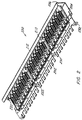
- FIGURE 1 is a perspective view of a panel assembly 10 made up of a front panel 100, a ground pan assembly 200 and a cover 300.
- Front panel 100 includes four slotted holes 102 for mounting the panel assembly 10 to a standard rack which is typically 19" wide.
- the ground pan assembly 200 is riveted to the front panel 100 and is described in detail below with reference to FIGURES 2-4.
- Cover 300 is secured to the ground pan assembly through fasteners and is described in detail below with reference to FIGURE 7.
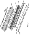
- FIGURE 2 is a perspective view of the ground pan assembly 200.
- the ground pan assembly includes a ground pan 202 having a generally flat, rectangular base 204 coupled to a front face 206.
- the front face 206 is substantially perpendicular to the base 204 and includes openings 208 (FIGURE 3) providing access to shielded outlets 210 mounted in the ground pan 202.
- Suitable shielded outlets 210 are shielded outlets sold under the trademark SM available from The Siemon Company.
- Shielded outlets 210 are part of a printed circuit board assembly 214 (FIGURE 3). It is understood that a variety of shielded outlets may be used and the present invention is not limited to printed circuit board mounted shielded outlets.
- the rectangular housing 211 of the shielded outlet 210 is conductive.
- a rearward facing lip 212 which is substantially perpendicular to front face 206. Lip 212 increases the strength of the ground pan 202 and provides a surface that directs the shield coupler against the shielded outlet 210 as described herein.
- the shield coupler 220 is positioned under the front lip 212 and riveted to back of the ground pan 202. The proper force is maintained between the distal portion 262 (FIGURE 4) of the shield coupler 220 and shielded housing 211 of the jack by positioning the distal portion 262 under lip 212.
- Shield couplers 220 provide a conductive path from the ground pan 202 to the conductive housing 211 of shielded outlets 210.
- a series of ground clips 222 secure the incoming cable to the shield couplers 220.
- Each ground clip 222 includes a planar section 224 having a hole 226 formed therein for receiving a fastener and two arcuate extensions 228 coupled to said planar section. The incoming cable is positioned beneath an arcuate extension 228 and is secured to the shielded coupler 220 though pressure from the ground clip 222.
- Ground pan 202 includes a plurality of fingers 230 having a space therebetween that provide for strain relief for the incoming cable.
- Ground pan 202 also includes a plurality of ground lugs 232 for electrically connecting the ground pan 202 to ground.
- FIGURE 4 is a perspective view of the shield coupler 220.
- the shield coupler 220 provides an electrical connection from the shield layer of an incoming cable to the conductive housing 211 of connector 210.
- the shield coupler 220 includes a generally planar base 250 which includes holes 252 for securing the shield coupler to the ground pan through fasteners.
- Base 250 includes a plurality of spades 254 extending away from the surface of base 250. Each spade 254 has a distal end 256 which is tapered to a rounded point.
- the spade 254 could be a removable component. Spade 254 facilitates installation of the incoming cable as described herein. Extending away from base 250 are a plurality of arms 258.
- Arms 258 bend approximately 90 degrees to define intermediate section 260 and then bend approximately 90 degrees to define a distal section 262.
- Distal section 262 is arcuate and is shaped in a curve that is directed downwards and then proceeds upwards to define an arcuate path.
- a downwardly extending protrusion 264 extends away from the arcuate surface. Protrusion 264 contacts the shielded outlet 211.
- the spade 254 facilitates connection of the shield layer of an incoming cable to the shield coupler 220.
- Shown in FIGURES 5 and 6 are two configurations for coupling a cable to the spade 254.
- Incoming cable 261 includes a shield or screen 263 having an interior surface 265 that is conductive.
- FIGURE 5 illustrates a first mounting configuration in which the screen 263 is folded back over the outside of the cable 261 so that the conductive surface 265 is exposed. The conductive surface 265 is placed in contact with spade 254 and held in place with ground clip 222.
- FIGURE 6 shows an alternative mounting arrangement in which the screen 263 is not folded over the outside of the cable 261. Rather, spade 254 is inserted into cable 261 so that the spade 254 contacts the interior, conductive surface 265 of the screen 263. The cable 261 is then secured in place through ground clip 222.
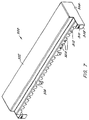
- FIGURE 7 is a perspective view of cover 300 having a top 302, two sides 304 and a rear wall 306.
- the side walls 304 extend past rear wall 306 and bend inwards approximately 90 degrees to define tab 308.
- Tab 308 includes a cable tie down protrusion having an opening therein for receiving a cable tie and securing incoming cable to the cover 300.
- the rear wall includes a plurality of notches 312 along a bottom surface of the rear wall. Each of the notches allows an incoming cable to enter the enclosure.
- the notches 312 are aligned with fingers 230 on ground pan 202.
- the cover 300 slides into place from the back enclosing the ground pan assembly and providing EMI/RFI protection.
- Affixed to the cover 300 in openings 312 is a conductive gasket 320 which conforms to the shape of the cable thus shielding the entire cable entrance area.
- the ground pan 202, ground clip 222 and cover 300 are required to be grounded with the mounting rack and are fabricated of cold rolled steel with a conductive zinc plating.
- the front panel 100 is not required to be electrically connected to the mounting rack and is fabricated from an anodized aluminum.
- the shield coupler 220 is required to be conductive and is made from brass with a nickel or tin plating.
- the present invention provides a system that effectively and economically complies with the requirements of transfer impedance and the category 5 transmission performance for national and international standards for connecting hardware and provides an easy method to terminate different types of screened cable.
Landscapes
- Engineering & Computer Science (AREA)
- Computer Networks & Wireless Communication (AREA)
- Health & Medical Sciences (AREA)
- Toxicology (AREA)
- Shielding Devices Or Components To Electric Or Magnetic Fields (AREA)
- Details Of Connecting Devices For Male And Female Coupling (AREA)
Claims (10)
- Panneau de raccordement blindé (10), comprenant :caractérisé en ce qu'il comprend en outre :un ensemble de panneau masse (200) comprenant un panneau masse (202) pour une connexion à la masse ;une pluralité de sorties (210) installées sur ledit panneau masse, chacune desdites sorties ayant un boítier de sortie conducteur (211) ; etcoupleur de blindage (220) relié électriquement audit panneau masse, ledit coupleur de blindage comprenant une cosse (254) pour établir un contact électrique avec un écran de masse dans un câble entrant et un bras (258) pour établir un contact électrique avec l'un desdits boítiers de sortie conducteurs.
- Panneau de raccordement selon la revendication 1, dans lequel ledit bras comporte une portion distale arquée.
- Panneau de raccordement selon la revendication 2, dans lequel ladite portion distale arquée comprend une protubérance pour mettre en contact ledit boítier de sortie conducteur.
- Panneau de raccordement selon la revendication 2, dans lequel l'ensemble de panneau masse comprend une base, une paroi avant et un rebord s'éloignant de ladite paroi avant, ladite portion distale arquée étant positionnée au-dessous dudit rebord.
- Panneau de raccordement selon la revendication 1, dans lequel l'ensemble de panneau masse comprend une pluralité de doigts espacés pour assurer une réduction de tension pour les câbles entrants.
- Panneau de raccordement selon la revendication 5, comprenant en outre un couvercle avec une pluralité d'encoches alignées sur lesdits doigts.
- Panneau de raccordement selon la revendication 1, dans lequel ladite cosse s'éloigne dudit coupleur de blindage et est conique.
- Panneau de raccordement selon la revendication 1, comprenant en outre une pluralité de collier de mise à la masse pour fixer les câbles entrants sur ledit ensemble de panneau masse.
- Panneau de raccordement selon la revendication 1, comprenant en outre un câble avec une gaine extérieure et une couche de blindage intérieure, ladite couche de blindage étant pliée sur ladite gaine extérieure et en contact électrique avec ladite cosse.
- Panneau de raccordement selon la revendication 1, comprenant en outre un câble avec une gaine extérieure et une couche de blindage intérieure, ladite couche de blindage étant contenue dans ladite gaine extérieure et ladite cosse positionnée dans ledit câble et en contact électrique avec ladite couche de blindage.
Applications Claiming Priority (6)
| Application Number | Priority Date | Filing Date | Title |
|---|---|---|---|
| US4922897P | 1997-06-09 | 1997-06-09 | |
| US49228 | 1997-06-09 | ||
| US85473 | 1998-05-27 | ||
| US09/085,473 US6074251A (en) | 1997-06-09 | 1998-05-27 | Shielded high density patch panel |
| PCT/US1998/011105 WO1998057398A1 (fr) | 1997-06-09 | 1998-06-01 | Panneau de raccordement blinde haute densite |
| 2003-03-28 |
Publications (3)
| Publication Number | Publication Date |
|---|---|
| EP0917745A1 EP0917745A1 (fr) | 1999-05-26 |
| EP0917745A4 EP0917745A4 (fr) | 2000-08-30 |
| EP0917745B1 true EP0917745B1 (fr) | 2004-04-21 |
Family
ID=21958720
Family Applications (1)
| Application Number | Title | Priority Date | Filing Date |
|---|---|---|---|
| EP98925083A Expired - Lifetime EP0917745B1 (fr) | 1997-06-09 | 1998-06-01 | Panneau de raccordement blinde haute densite |
Country Status (5)
| Country | Link |
|---|---|
| US (1) | US6074251A (fr) |
| EP (1) | EP0917745B1 (fr) |
| CN (1) | CN1228203A (fr) |
| DE (1) | DE69823308T2 (fr) |
| WO (1) | WO1998057398A1 (fr) |
Families Citing this family (20)
| Publication number | Priority date | Publication date | Assignee | Title |
|---|---|---|---|---|
| TW399818U (en) | 1998-11-20 | 2000-07-21 | Molex Inc | Structure of connector |
| JP3504541B2 (ja) * | 1999-08-19 | 2004-03-08 | ケル株式会社 | シールドコネクタ |
| DE19947086A1 (de) * | 1999-09-30 | 2001-05-03 | Rxs Schrumpftech Garnituren | Verteilereinrichtung für eine Telekommunikationsanlage |
| US6267607B1 (en) * | 1999-11-23 | 2001-07-31 | Lucent Technologies Inc. | Anti-rotation ground clip for faceplates |
| IL142157A (en) * | 2001-03-21 | 2008-03-20 | Rit Techn Ltd | Patch panel |
| US20040209515A1 (en) * | 2003-04-03 | 2004-10-21 | Caveney Jack E. | High density patch panel |
| JP4124760B2 (ja) * | 2003-12-22 | 2008-07-23 | モレックス インコーポレーテッド | 同軸ケーブル用コネクタ及びケーブル保持具 |
| US6824426B1 (en) * | 2004-02-10 | 2004-11-30 | Hon Hai Precision Ind. Co., Ltd. | High speed electrical cable assembly |
| DE102008022858B4 (de) | 2007-06-25 | 2023-10-12 | Icotek Project Gmbh & Co. Kg | Vorrichtung zum Halten von Kabeln |
| EP2151908B1 (fr) * | 2008-08-04 | 2010-10-06 | Siemens Aktiengesellschaft | Machine dynamoélectrique dotée d'un boîtier de connexion en plusieurs parties |
| US20100221955A1 (en) * | 2009-02-27 | 2010-09-02 | Tyco Electronics Corporation | Cassette having interchangable rear mating connectors |
| US7909643B2 (en) * | 2009-02-27 | 2011-03-22 | Tyco Electronics Corporation | Cassette for a cable interconnect system |
| US7909622B2 (en) | 2009-02-27 | 2011-03-22 | Tyco Electronics Corporation | Shielded cassette for a cable interconnect system |
| US7878824B2 (en) * | 2009-02-27 | 2011-02-01 | Tyco Electronics Corporation | Shielded cassette for a cable interconnect system |
| US7909619B2 (en) * | 2009-02-27 | 2011-03-22 | Tyco Electronics Corporation | Cassette with locking feature |
| US8062049B2 (en) * | 2010-01-15 | 2011-11-22 | Tyco Electronics Corporation | Latch assembly for a connector assembly |
| US8096833B2 (en) * | 2010-01-15 | 2012-01-17 | Tyco Electronics Corporation | Plug assembly |
| US8337238B2 (en) | 2010-07-19 | 2012-12-25 | Tyco Electronics Corporation | Cable clip for a connector assembly |
| JP5088427B2 (ja) * | 2011-03-02 | 2012-12-05 | 第一精工株式会社 | 電気コネクタ及び電気コネクタ組立体 |
| US10367294B1 (en) * | 2018-03-08 | 2019-07-30 | Te Connectivity Corporation | Electrical device having a ground termination component with strain relief |
Family Cites Families (12)
| Publication number | Priority date | Publication date | Assignee | Title |
|---|---|---|---|---|
| US4571012A (en) * | 1984-12-21 | 1986-02-18 | Molex Incorporated | Shielded electrical connector assembly |
| US5259772A (en) * | 1990-06-08 | 1993-11-09 | E. I. Du Pont De Nemours And Company | Connectors with ground structure |
| US5466175A (en) * | 1992-02-27 | 1995-11-14 | Yazaki Corporation | Shield connector connecting shield cables |
| US5518421A (en) * | 1993-01-26 | 1996-05-21 | The Whitaker Corporation | Two piece shell for a connector |
| US5380223A (en) * | 1993-11-24 | 1995-01-10 | The Whitaker Corporation | High density electrical connector |
| US5683269A (en) * | 1995-03-27 | 1997-11-04 | The Whitaker Corporation | Shielded electrical connector with cable strain relief |
| JP2757139B2 (ja) * | 1995-04-04 | 1998-05-25 | 日本航空電子工業株式会社 | シールド型コネクタ |
| DE19542967A1 (de) * | 1995-11-17 | 1997-05-22 | Whitaker Corp | Abgeschirmtes Gehäuse |
| US5639267A (en) * | 1996-01-26 | 1997-06-17 | Maxconn Incorporated | Modular jack assembly |
| US5688145A (en) * | 1996-01-29 | 1997-11-18 | Dan Chief Enterprise Co., Ltd. | Adapter socket structure and method for forming same |
| US5766041A (en) * | 1996-05-31 | 1998-06-16 | The Whitaker Corporation | Shield member for panel mount connector |
| US5807137A (en) * | 1996-10-04 | 1998-09-15 | Molex Incorporated | Shielded electrical receptacle connector assembly |
-
1998
- 1998-05-27 US US09/085,473 patent/US6074251A/en not_active Expired - Fee Related
- 1998-06-01 CN CN98800785A patent/CN1228203A/zh active Pending
- 1998-06-01 WO PCT/US1998/011105 patent/WO1998057398A1/fr not_active Ceased
- 1998-06-01 EP EP98925083A patent/EP0917745B1/fr not_active Expired - Lifetime
- 1998-06-01 DE DE69823308T patent/DE69823308T2/de not_active Expired - Fee Related
Also Published As
| Publication number | Publication date |
|---|---|
| DE69823308D1 (de) | 2004-05-27 |
| CN1228203A (zh) | 1999-09-08 |
| DE69823308T2 (de) | 2005-05-12 |
| WO1998057398A1 (fr) | 1998-12-17 |
| EP0917745A4 (fr) | 2000-08-30 |
| US6074251A (en) | 2000-06-13 |
| EP0917745A1 (fr) | 1999-05-26 |
Similar Documents
| Publication | Publication Date | Title |
|---|---|---|
| US6074251A (en) | Shielded high density patch panel | |
| EP0881714B1 (fr) | Connecteur électrique blindé | |
| US4687263A (en) | Shielding kit for electrical connectors terminating multiconductor 360 degree shielded cable | |
| CA2034114C (fr) | Systeme de couplage modulaire a grande densite pour les communications | |
| EP1356549B1 (fr) | Interface de connecteur et systeme de retenue destines a un connecteur haute densite | |
| US6142828A (en) | Shielded connector having adjustable cable exit | |
| US5562493A (en) | Network interface assembly and mounting frame | |
| US4838811A (en) | Modular connector with EMI countermeasure | |
| US6231392B1 (en) | Cable interconnection | |
| US6017245A (en) | Stamped backshell assembly with integral front shield and rear cable clamp | |
| EP0551768B1 (fr) | Dispositif de câblage pour circuit de distribution | |
| EP0822623B1 (fr) | Blindage pour un connecteur jack modulaire | |
| CN1119844C (zh) | 屏蔽电联接器 | |
| US4537458A (en) | Conductive shielding housing for flat cable connector | |
| US5733146A (en) | Shield for modular electrical connector | |
| US4986779A (en) | Local area network interface | |
| US5772471A (en) | Panel mount bracket for electrical connector | |
| US5447441A (en) | Connector box for shielded cables | |
| EP0165490B1 (fr) | Douille pour une plaque à circuit imprimé pour un cordon terminé par une fiche connectrice modulaire | |
| EP0224200A2 (fr) | Connecteur fiche et douille blindé | |
| US20080038963A1 (en) | Receptacle connector and apparatus having the same | |
| EP0836249A1 (fr) | Enveloppe électrique de mise à la terre | |
| JPS629985B2 (fr) | ||
| US5667407A (en) | Shielded cable plug | |
| EP0431206B1 (fr) | Connecteur à blindage de mise à la terre et procédé |
Legal Events
| Date | Code | Title | Description |
|---|---|---|---|
| PUAI | Public reference made under article 153(3) epc to a published international application that has entered the european phase |
Free format text: ORIGINAL CODE: 0009012 |
|
| 17P | Request for examination filed |
Effective date: 19990226 |
|
| AK | Designated contracting states |
Kind code of ref document: A1 Designated state(s): DE FR GB |
|
| A4 | Supplementary search report drawn up and despatched |
Effective date: 20000717 |
|
| AK | Designated contracting states |
Kind code of ref document: A4 Designated state(s): DE FR GB |
|
| GRAP | Despatch of communication of intention to grant a patent |
Free format text: ORIGINAL CODE: EPIDOSNIGR1 |
|
| GRAS | Grant fee paid |
Free format text: ORIGINAL CODE: EPIDOSNIGR3 |
|
| GRAA | (expected) grant |
Free format text: ORIGINAL CODE: 0009210 |
|
| AK | Designated contracting states |
Kind code of ref document: B1 Designated state(s): DE FR GB |
|
| REG | Reference to a national code |
Ref country code: GB Ref legal event code: FG4D |
|
| REF | Corresponds to: |
Ref document number: 69823308 Country of ref document: DE Date of ref document: 20040527 Kind code of ref document: P |
|
| ET | Fr: translation filed | ||
| PLBE | No opposition filed within time limit |
Free format text: ORIGINAL CODE: 0009261 |
|
| STAA | Information on the status of an ep patent application or granted ep patent |
Free format text: STATUS: NO OPPOSITION FILED WITHIN TIME LIMIT |
|
| 26N | No opposition filed |
Effective date: 20050124 |
|
| PGFP | Annual fee paid to national office [announced via postgrant information from national office to epo] |
Ref country code: GB Payment date: 20070628 Year of fee payment: 10 |
|
| PGFP | Annual fee paid to national office [announced via postgrant information from national office to epo] |
Ref country code: FR Payment date: 20070618 Year of fee payment: 10 |
|
| GBPC | Gb: european patent ceased through non-payment of renewal fee |
Effective date: 20080601 |
|
| REG | Reference to a national code |
Ref country code: FR Ref legal event code: ST Effective date: 20090228 |
|
| PG25 | Lapsed in a contracting state [announced via postgrant information from national office to epo] |
Ref country code: GB Free format text: LAPSE BECAUSE OF NON-PAYMENT OF DUE FEES Effective date: 20080601 |
|
| PG25 | Lapsed in a contracting state [announced via postgrant information from national office to epo] |
Ref country code: FR Free format text: LAPSE BECAUSE OF NON-PAYMENT OF DUE FEES Effective date: 20080630 |
|
| PGFP | Annual fee paid to national office [announced via postgrant information from national office to epo] |
Ref country code: DE Payment date: 20090619 Year of fee payment: 12 |
|
| PG25 | Lapsed in a contracting state [announced via postgrant information from national office to epo] |
Ref country code: DE Free format text: LAPSE BECAUSE OF NON-PAYMENT OF DUE FEES Effective date: 20110101 |