EP0917814A2 - Landwirtschaftliche Geräte - Google Patents
Landwirtschaftliche Geräte Download PDFInfo
- Publication number
- EP0917814A2 EP0917814A2 EP98305213A EP98305213A EP0917814A2 EP 0917814 A2 EP0917814 A2 EP 0917814A2 EP 98305213 A EP98305213 A EP 98305213A EP 98305213 A EP98305213 A EP 98305213A EP 0917814 A2 EP0917814 A2 EP 0917814A2
- Authority
- EP
- European Patent Office
- Prior art keywords
- rotor
- clod
- elements
- recesses
- implement
- Prior art date
- Legal status (The legal status is an assumption and is not a legal conclusion. Google has not performed a legal analysis and makes no representation as to the accuracy of the status listed.)
- Granted
Links
- 239000002689 soil Substances 0.000 claims description 30
- 238000010951 particle size reduction Methods 0.000 claims description 9
- 238000000034 method Methods 0.000 claims description 7
- 238000005520 cutting process Methods 0.000 claims description 4
- 230000000694 effects Effects 0.000 description 25
- 238000010276 construction Methods 0.000 description 6
- 239000000463 material Substances 0.000 description 5
- 229910000831 Steel Inorganic materials 0.000 description 3
- 238000004519 manufacturing process Methods 0.000 description 3
- 239000010959 steel Substances 0.000 description 3
- 239000002245 particle Substances 0.000 description 2
- 238000005096 rolling process Methods 0.000 description 2
- 229910000760 Hardened steel Inorganic materials 0.000 description 1
- 238000005299 abrasion Methods 0.000 description 1
- 230000004323 axial length Effects 0.000 description 1
- 230000009286 beneficial effect Effects 0.000 description 1
- 238000005266 casting Methods 0.000 description 1
- 238000005056 compaction Methods 0.000 description 1
- 239000002131 composite material Substances 0.000 description 1
- 230000003247 decreasing effect Effects 0.000 description 1
- 239000000446 fuel Substances 0.000 description 1
- 230000002401 inhibitory effect Effects 0.000 description 1
- 238000007689 inspection Methods 0.000 description 1
- 230000003993 interaction Effects 0.000 description 1
- 239000000203 mixture Substances 0.000 description 1
- 238000007493 shaping process Methods 0.000 description 1
- 238000003971 tillage Methods 0.000 description 1
- XLYOFNOQVPJJNP-UHFFFAOYSA-N water Substances O XLYOFNOQVPJJNP-UHFFFAOYSA-N 0.000 description 1
- 230000003313 weakening effect Effects 0.000 description 1
Images


Classifications
-
- A—HUMAN NECESSITIES
- A01—AGRICULTURE; FORESTRY; ANIMAL HUSBANDRY; HUNTING; TRAPPING; FISHING
- A01B—SOIL WORKING IN AGRICULTURE OR FORESTRY; PARTS, DETAILS, OR ACCESSORIES OF AGRICULTURAL MACHINES OR IMPLEMENTS, IN GENERAL
- A01B27/00—Clod-crushers
Definitions
- This invention relates to agricultural implements. More specifically, the invention provides an implement having improved performance with respect to tilth production, and especially with respect to tilth production from soils having a very high clod content.
- an agricultural implement adapted to carry out soil particle size reduction, as defined in the accompanying claims.
- I provide an agricultural implement in which a rotor is adapted to effect a clod-crushing or particle-size-reduction effect (as opposed to a clod-cutting or clod-impacting effect) by defining clod-receiving recesses between projecting elements of the rotor. Clods are received in the recesses and, in use, can be crushed by the weight of the rotor and its associated structures.
- this known crushing arrangement is reversed in the sense that I provide a roller which is so constructed that there is an inward crushing effect as opposed to an outward crushing effect. This is achieved by defining within the rotor clod-receiving recesses which, in use, receive clods and the thus-received clods are then crushed inwardly by the externally-applied inward pressure of the remainder of the soil or clods.
- the clod-receiving recesses are defined by projecting elements which project outwardly from a generally central drum.
- the general structure and disposition of the projections is such that they co-operate with each other to define the clod-receiving recesses. So far as the clods are concerned, the arrangement is such that inward movement of the clods under the effect of the inwardly-directed crushing loads is prevented not only by the projections themselves but also by the drum structure itself. Lateral movement of any given clod is likewise limited or prevented by the adjacent projections.
- the projections or projecting elements are so constructed and disposed that they cause the rotor somewhat to resemble a cylindrical brush, as viewed in the generally lengthwise direction of the rotor, and from above.
- the "bristles" of this "brush" are constituted by the projecting elements themselves which are of a rigid steel construction (and thus no brush-like flexibility is intended to be implied), but a proper understanding of the invention requires an appreciation of the general structure of the rotor and the distinctions between it and the many previously proposed rotors which have been used for various tillage operations. None however, to the best of the applicant's knowledge, has ever been used for a clod-crushing effect in this way.
- GB 330 discloses a rolling harrow in which the rotor is shown in Fig 1 and has four outwardly tapering finger elements mounted on each individual rotor and the disposition of the rotors is shown in Figs 2 and 3.
- the mode of operation is purely a particle size reduction on the basis of impact since no possibility exists of any crushing effect because the spaces available for clod movement preclude all possibility of clod holding.
- the structure which defines the clod-receiving recesses is provided by projecting elements. These are formed in the embodiments as hardened steel fabrications (in the sense of having been produced by a steel cutting and shaping technique). Corresponding castings could be employed, and in such a case the projecting elements may have outwardly tapering side faces (in addition to their leading and trailing edges) so that the projecting elements have sharper points and define additional recess space between one element and the next.
- the projecting elements are disposed in circumferentially-extending rows and project outwardly from the central drum of the rotor. In terms of actual construction, the individual rows of projections are spaced apart by individual rings (forming the drum) at suitable spacings.
- the implement comprises two rotor gangs disposed in series, one in front of the other and at right angles to the travel direction in normal usage.
- the implement could be semi-mounted or even fully mounted on the tractor hitch linkage.
- One, two or even three or more rotors could be employed depending upon the soil conditions to be encountered and cost and weight factors.
- the rotors may be provided with progressively more tightly-packed projecting elements so as to accommodate the progressively decreasing sizes of the soil clods or particles.
- the implement hitching arrangement employs a drawbar which is trailed at its forward end from the tractor and at its rearward end is pivotally connected to the implement frame about a transverse axis.
- An hydraulic ram acts between the drawbar and a raised portion on the implement frame so that, by retraction of the ram, a force tending to pivot the implement frame relative to the drawbar exerts a generally lifting effect on the rearward portion of the frame so as to transfer weight onto the front rotor.
- the weight of the implement this is chosen to be the maximum consistent with acceptable material costs and transportability.
- Implement weight can be increased by means of the usual expedients of add-on concrete weights or, in this case, the filling of the rotors (which in such a case therefore require to be constructed in water-tight format) with water.
- the implement has a weight of approximately 1.5 tonnes per metre of implement width.
- the implement is provided with clod-lifting elements in the form of tines adapted to enter the soil ahead of the rotors in use and to raise clods for crushing by the rotors.
- the projecting elements themselves have a generally curved format, being generally finger shaped, tapering outwardly, and being curved in a direction such that the curved and tapering outer end of each projection extends in a generally trailing (as opposed to a leading) direction with respect to rotor rotation during use.
- a generally curved format being generally finger shaped, tapering outwardly, and being curved in a direction such that the curved and tapering outer end of each projection extends in a generally trailing (as opposed to a leading) direction with respect to rotor rotation during use.
- the disposition of the curvature or angular inclination of the projecting elements may not necessarily be in the above-discussed direction but may be in the opposite direction or indeed purely radial for certain purposes and the rotor may comprise a mixture of such directions to contribute to an overall composite or hybrid effect on the soil.
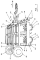
- an agricultural implement 10 adapted to carry out soil particle size reduction in the form of clod-crushing comprises a pair or rotors 12, 14 each mounted to rotate, in use, about a respective generally horizontal axis 16, 18.
- Each rotor comprises a central generally drum-like structure 20, the drum having projecting elements 22 adapted to contribute in use to the clod crushing effect to be more fully described below.
- Means 24 to rotate the rotors 12, 14 is provided comprising an implement frame 26 and a drawbar 28, whereby implement 10 is drawn in use in the direction F of normal forward motion, thereby causing rotors 12, 14 to rotate in the directions shown, by virtue of the rotors being mounted on respective end bearings carried by mounting plates 30, 32 at each end thereof - see Figs 2 and 3.
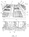
- the projecting elements 22 are disposed in a plurality of rows 34 (see Fig 4) at axially spaced intervals along the axial length of the drum like structure 20.
- Rotors 12, 14 are constructed to act, in use, as clod-crushing rotors, as opposed to clod-cutting or clod-impacting rotors.
- the rotors define clod-receiving recesses 36 between the projecting elements 22. In these recesses 36 clods 38 are received and are crushed by the weight of the rotor and associated structures.
- the clod-recess-defining projecting elements 22 in one row 34 of same define the limits of the recesses 36 in the circumferential direction of the rotor between adjacent edges of successive pairs of such projecting elements in the row. Moreover, the clod-recess-defining projecting elements define the limits of the recesses in the axial direction of the rotor likewise, such limits being defined between at least one of the projecting elements in each of the two adjacent rows 34 of projecting elements 22 at each side of the one particular such row.
- the clod-recess-defining-projecting elements 22 are of generally outwardly-tapering finger-like format whereby the clod-receiving recesses 36 are of correspondingly generally radially inwardly-tapering form as viewed in the axial direction of the rotors 12, 14 and as defined between the mutually converging edges 40, 42 of the projecting elements.
- the projecting elements 22 extend outwardly, as measured in a radial direction from the drum 20 a distance which is less than the overall radius of the drum. This can be seen by simple inspection in Fig 3.
- the projecting elements may be somewhat longer and even up to the radius of the drum in some cases.
- the projecting elements 22 are disposed relative to each other so as to form a generally toothed brush-like format of the rotors 12, 14 as viewed from above and to one side (as in Figs 2 and 3) in which the rigid projections 22 (forming the teeth of the brush) are disposed in a generally cylindrical format and defined between them the clod-receiving recesses 36.
- Projecting elements 22 are of generally curved form having their mutually converging convex edges 40 and concave edges 42 disposed as shown.
- the convex edge 40 is, in use, effectively the leading edge with respect to the direction D of rotation of the rotors 12, 14.
- Clod lifting elements 44 in the form of tines are mounted on the implement frame 26 so as to enter the soil ahead of the rotors 12, 14 in use and thereby raise clods for crushing by the rotors.
- Scraper elements 46 are mounted to enter between the rows 34 of projecting elements 22 so that soil is removed from between the projecting elements by movement of the scraper elements in the direction (due to the curvature of those elements) from the inward narrow end of the recesses 36 towards the outer and wider end thereof.
- Means is provided to vary the proportion of the downward loading carried by each of the rotors 12, 14 in accordance with conditions during use.
- drawbar 28 is pivotally connected to the implement frame 26 about a generally horizontal transverse axis (not shown) whereby (effectively) the drawbar can pivot up and down relative to the frame.
- a hydraulic ram 48 acts between drawbar 28 and a raised portion 50 of frame 26. When ram 48 is retracted, this tends to cause lifting of the rear portion of implement frame 26 (because the front portion of drawbar 28 is maintained at a fixed height by the tractor coupled thereto) thereby transferring weight from the rear rotor 14 to the front rotor 12.
- Fig 1 the other main constructional feature shown is the facility for width-reduction for transport purposes. This is achieved by means of two pairs of gang-folding rams 52, 54 which fold the lateral side halves of implement frame 26 inwardly and upwardly about a generally horizontal fore/aft axis (not shown) to a relatively narrow upright position for transport purposes in which the implement 10 is carried on rear transport wheels 56.
- the clod lifting elements or tines 44 are arranged in two banks 58, 60 disposed in front of their respective rotors 12, 14.
- Each rotor has its own corresponding bank 62 of scraper elements 46.
- bank 62 of scraper elements 46 For simplicity of illustration, only one of these banks is shown, namely the one which acts in relation to the rear rotor 14, and for clarity of illustration it is shown not inter-engaging with the projecting elements 22, but merely at the relevant side (the rear side) of its rotor for relatively low power consumption, as explained above.
- One disposition of the scraper elements 46 in relation to the rotors is seen in Figs 2 and 3. The preferred position is just above ground level so as to remove crushed material with minimum power consumption.
- Fig 1 shows this disposition in respect of bank 62 of scraper elements 46, the scraper elements being supported on a suspended bar just above ground level.
Landscapes
- Life Sciences & Earth Sciences (AREA)
- Engineering & Computer Science (AREA)
- Mechanical Engineering (AREA)
- Soil Sciences (AREA)
- Environmental Sciences (AREA)
- Soil Working Implements (AREA)
- Mushroom Cultivation (AREA)
- Catching Or Destruction (AREA)
- Cyclones (AREA)
Applications Claiming Priority (2)
| Application Number | Priority Date | Filing Date | Title |
|---|---|---|---|
| GB9713770 | 1997-07-01 | ||
| GBGB9713770.7A GB9713770D0 (en) | 1997-07-01 | 1997-07-01 | Agricultural implements |
Publications (3)
| Publication Number | Publication Date |
|---|---|
| EP0917814A2 true EP0917814A2 (de) | 1999-05-26 |
| EP0917814A3 EP0917814A3 (de) | 2004-03-03 |
| EP0917814B1 EP0917814B1 (de) | 2009-12-09 |
Family
ID=10815130
Family Applications (1)
| Application Number | Title | Priority Date | Filing Date |
|---|---|---|---|
| EP98305213A Expired - Lifetime EP0917814B1 (de) | 1997-07-01 | 1998-07-01 | Landwirtschaftliche Geräte |
Country Status (4)
| Country | Link |
|---|---|
| EP (1) | EP0917814B1 (de) |
| AT (1) | ATE451007T1 (de) |
| DE (1) | DE69841356D1 (de) |
| GB (2) | GB9713770D0 (de) |
Cited By (3)
| Publication number | Priority date | Publication date | Assignee | Title |
|---|---|---|---|---|
| CN115024049A (zh) * | 2022-06-07 | 2022-09-09 | 盐城璟甡电子科技有限公司 | 一种播种机的镇压装置 |
| US11558988B2 (en) | 2019-08-29 | 2023-01-24 | Cnh Industrial America Llc | Rotary ground engaging tool with double loop barbed links |
| RU220912U1 (ru) * | 2023-05-11 | 2023-10-11 | Федеральное государственное бюджетное образовательное учреждение высшего образования "Брянский государственный аграрный университет" | Орудие для поверхностной обработки почвы |
Families Citing this family (1)
| Publication number | Priority date | Publication date | Assignee | Title |
|---|---|---|---|---|
| RU195351U1 (ru) * | 2019-05-22 | 2020-01-23 | Акционерное общество "Алтайский завод сельскохозяйственного машиностроения" | Прицепное устройство чизельного плуга для обработки почвы |
Citations (5)
| Publication number | Priority date | Publication date | Assignee | Title |
|---|---|---|---|---|
| GB304330A (en) | 1928-01-19 | 1929-12-12 | Jean Laubain | Improvements in or relating to harrows |
| GB722000A (en) | 1950-03-11 | 1955-01-19 | Ferguson Harry Inc | Improvements relating to rotary hoes |
| GB1401800A (en) | 1971-08-13 | 1975-07-30 | Mccoomb J M | Cultivating implements |
| US4533000A (en) | 1982-07-30 | 1985-08-06 | Lely Cornelis V D | Soil cultivating implements |
| EP0338646A2 (de) | 1988-04-20 | 1989-10-25 | C. van der Lely N.V. | Kultivator |
Family Cites Families (6)
| Publication number | Priority date | Publication date | Assignee | Title |
|---|---|---|---|---|
| US1931960A (en) * | 1932-12-07 | 1933-10-24 | Edward E Greiner | Combination mulching, harrowing, hoeing and rolling machine |
| US4195695A (en) * | 1977-12-30 | 1980-04-01 | The United States Of America As Represented By The Secretary Of Agriculture | Land imprinter |
| DE7838544U1 (de) * | 1978-12-27 | 1982-03-25 | Amazonen-Werke H. Dreyer Gmbh & Co Kg, 4507 Hasbergen | Bodenwalze |
| DE8417015U1 (de) * | 1984-06-04 | 1984-09-13 | Wolf-Geräte GmbH, 5240 Betzdorf | Bodenbearbeitungs-handgeraet |
| EP0168328B1 (de) * | 1984-07-11 | 1989-10-11 | Claude Prieur | Landwirtschaftliches Gerät wie z.B. ein Krümler |
| NL8801489A (nl) * | 1988-06-10 | 1990-01-02 | Lely Nv C Van Der | Grondbewerkingsmachine. |
-
1997
- 1997-07-01 GB GBGB9713770.7A patent/GB9713770D0/en active Pending
-
1998
- 1998-07-01 EP EP98305213A patent/EP0917814B1/de not_active Expired - Lifetime
- 1998-07-01 DE DE69841356T patent/DE69841356D1/de not_active Expired - Lifetime
- 1998-07-01 GB GB9814207A patent/GB2326809B/en not_active Expired - Fee Related
- 1998-07-01 AT AT98305213T patent/ATE451007T1/de not_active IP Right Cessation
Patent Citations (5)
| Publication number | Priority date | Publication date | Assignee | Title |
|---|---|---|---|---|
| GB304330A (en) | 1928-01-19 | 1929-12-12 | Jean Laubain | Improvements in or relating to harrows |
| GB722000A (en) | 1950-03-11 | 1955-01-19 | Ferguson Harry Inc | Improvements relating to rotary hoes |
| GB1401800A (en) | 1971-08-13 | 1975-07-30 | Mccoomb J M | Cultivating implements |
| US4533000A (en) | 1982-07-30 | 1985-08-06 | Lely Cornelis V D | Soil cultivating implements |
| EP0338646A2 (de) | 1988-04-20 | 1989-10-25 | C. van der Lely N.V. | Kultivator |
Cited By (4)
| Publication number | Priority date | Publication date | Assignee | Title |
|---|---|---|---|---|
| US11558988B2 (en) | 2019-08-29 | 2023-01-24 | Cnh Industrial America Llc | Rotary ground engaging tool with double loop barbed links |
| CN115024049A (zh) * | 2022-06-07 | 2022-09-09 | 盐城璟甡电子科技有限公司 | 一种播种机的镇压装置 |
| CN115024049B (zh) * | 2022-06-07 | 2024-06-11 | 河南天佑佳禾农业科技有限公司 | 一种播种机的镇压装置 |
| RU220912U1 (ru) * | 2023-05-11 | 2023-10-11 | Федеральное государственное бюджетное образовательное учреждение высшего образования "Брянский государственный аграрный университет" | Орудие для поверхностной обработки почвы |
Also Published As
| Publication number | Publication date |
|---|---|
| DE69841356D1 (de) | 2010-01-21 |
| GB9713770D0 (en) | 1997-09-03 |
| GB2326809B (en) | 2000-03-01 |
| EP0917814B1 (de) | 2009-12-09 |
| EP0917814A3 (de) | 2004-03-03 |
| GB9814207D0 (en) | 1998-09-02 |
| ATE451007T1 (de) | 2009-12-15 |
| GB2326809A (en) | 1999-01-06 |
Similar Documents
| Publication | Publication Date | Title |
|---|---|---|
| US5628372A (en) | Land management apparatus for creating irrigation pools | |
| US3750758A (en) | Farming implement for ridging | |
| US4987959A (en) | Farm machine for working the soil | |
| US4412588A (en) | Soil cultivating implements | |
| EP0917814B1 (de) | Landwirtschaftliche Geräte | |
| US4131163A (en) | Stubble eradicating implement | |
| GB1566465A (en) | Soil cultivating implements | |
| GB1587289A (en) | Soil cultivating implements | |
| US3705628A (en) | Sod cultivator | |
| GB2102261A (en) | Soil cultivating implement | |
| CN203120404U (zh) | 新型联合整地机 | |
| EP2401899B1 (de) | Landwirtschaftliches Gerät | |
| EP1310144B1 (de) | Bodenbearbeitungsgerät zum Einebnen, Zerkleinern und Rückverfestigen des Bodens | |
| US5417238A (en) | Tillage implements | |
| GB2127262A (en) | A soil cultivating machine | |
| RU2259698C1 (ru) | Комбинированное почвообрабатывающее орудие | |
| US4189006A (en) | Soil cultivating implements | |
| RU2524088C1 (ru) | Почвообрабатывающая фрезерная машина | |
| GB1579594A (en) | Soil crumbling rollers | |
| RU148556U1 (ru) | Кольчато-шпоровый рабочий орган сельскохозяйственных машин | |
| CA1134194A (en) | Soil working implement comprising a tined cultivator and a trailing knife rotor | |
| GB2023382A (en) | Soil cultivating | |
| JP2004121018A (ja) | 畦切り装置 | |
| GB2145913A (en) | Agricultural ground rollers | |
| RU130189U1 (ru) | Почвообрабатывающая фрезерная машина |
Legal Events
| Date | Code | Title | Description |
|---|---|---|---|
| PUAI | Public reference made under article 153(3) epc to a published international application that has entered the european phase |
Free format text: ORIGINAL CODE: 0009012 |
|
| AK | Designated contracting states |
Kind code of ref document: A2 Designated state(s): AT BE CH CY DE DK ES FI FR GB GR IE IT LI LU MC NL PT SE |
|
| AX | Request for extension of the european patent |
Free format text: AL;LT;LV;MK;RO;SI |
|
| PUAL | Search report despatched |
Free format text: ORIGINAL CODE: 0009013 |
|
| AK | Designated contracting states |
Kind code of ref document: A3 Designated state(s): AT BE CH CY DE DK ES FI FR GB GR IE IT LI LU MC NL PT SE |
|
| AX | Request for extension of the european patent |
Extension state: AL LT LV MK RO SI |
|
| RIC1 | Information provided on ipc code assigned before grant |
Ipc: 7A 01B 21/04 B Ipc: 7A 01B 29/04 B Ipc: 7A 01B 27/00 A |
|
| 17P | Request for examination filed |
Effective date: 20040804 |
|
| AKX | Designation fees paid |
Designated state(s): AT BE CH CY DE DK ES FI FR GB GR IE IT LI LU MC NL PT SE |
|
| 17Q | First examination report despatched |
Effective date: 20041119 |
|
| GRAP | Despatch of communication of intention to grant a patent |
Free format text: ORIGINAL CODE: EPIDOSNIGR1 |
|
| GRAS | Grant fee paid |
Free format text: ORIGINAL CODE: EPIDOSNIGR3 |
|
| GRAA | (expected) grant |
Free format text: ORIGINAL CODE: 0009210 |
|
| AK | Designated contracting states |
Kind code of ref document: B1 Designated state(s): AT BE CH CY DE DK ES FI FR GB GR IE IT LI LU MC NL PT SE |
|
| REG | Reference to a national code |
Ref country code: GB Ref legal event code: FG4D |
|
| REG | Reference to a national code |
Ref country code: CH Ref legal event code: EP |
|
| REG | Reference to a national code |
Ref country code: IE Ref legal event code: FG4D |
|
| REF | Corresponds to: |
Ref document number: 69841356 Country of ref document: DE Date of ref document: 20100121 Kind code of ref document: P |
|
| REG | Reference to a national code |
Ref country code: NL Ref legal event code: VDEP Effective date: 20091209 |
|
| PG25 | Lapsed in a contracting state [announced via postgrant information from national office to epo] |
Ref country code: SE Free format text: LAPSE BECAUSE OF FAILURE TO SUBMIT A TRANSLATION OF THE DESCRIPTION OR TO PAY THE FEE WITHIN THE PRESCRIBED TIME-LIMIT Effective date: 20091209 Ref country code: FI Free format text: LAPSE BECAUSE OF FAILURE TO SUBMIT A TRANSLATION OF THE DESCRIPTION OR TO PAY THE FEE WITHIN THE PRESCRIBED TIME-LIMIT Effective date: 20091209 |
|
| PG25 | Lapsed in a contracting state [announced via postgrant information from national office to epo] |
Ref country code: AT Free format text: LAPSE BECAUSE OF FAILURE TO SUBMIT A TRANSLATION OF THE DESCRIPTION OR TO PAY THE FEE WITHIN THE PRESCRIBED TIME-LIMIT Effective date: 20091209 |
|
| PG25 | Lapsed in a contracting state [announced via postgrant information from national office to epo] |
Ref country code: PT Free format text: LAPSE BECAUSE OF FAILURE TO SUBMIT A TRANSLATION OF THE DESCRIPTION OR TO PAY THE FEE WITHIN THE PRESCRIBED TIME-LIMIT Effective date: 20100409 Ref country code: NL Free format text: LAPSE BECAUSE OF FAILURE TO SUBMIT A TRANSLATION OF THE DESCRIPTION OR TO PAY THE FEE WITHIN THE PRESCRIBED TIME-LIMIT Effective date: 20091209 Ref country code: ES Free format text: LAPSE BECAUSE OF FAILURE TO SUBMIT A TRANSLATION OF THE DESCRIPTION OR TO PAY THE FEE WITHIN THE PRESCRIBED TIME-LIMIT Effective date: 20100320 |
|
| PG25 | Lapsed in a contracting state [announced via postgrant information from national office to epo] |
Ref country code: BE Free format text: LAPSE BECAUSE OF FAILURE TO SUBMIT A TRANSLATION OF THE DESCRIPTION OR TO PAY THE FEE WITHIN THE PRESCRIBED TIME-LIMIT Effective date: 20091209 |
|
| PLBE | No opposition filed within time limit |
Free format text: ORIGINAL CODE: 0009261 |
|
| STAA | Information on the status of an ep patent application or granted ep patent |
Free format text: STATUS: NO OPPOSITION FILED WITHIN TIME LIMIT |
|
| PG25 | Lapsed in a contracting state [announced via postgrant information from national office to epo] |
Ref country code: GR Free format text: LAPSE BECAUSE OF FAILURE TO SUBMIT A TRANSLATION OF THE DESCRIPTION OR TO PAY THE FEE WITHIN THE PRESCRIBED TIME-LIMIT Effective date: 20100310 Ref country code: CY Free format text: LAPSE BECAUSE OF FAILURE TO SUBMIT A TRANSLATION OF THE DESCRIPTION OR TO PAY THE FEE WITHIN THE PRESCRIBED TIME-LIMIT Effective date: 20091209 |
|
| 26N | No opposition filed |
Effective date: 20100910 |
|
| PG25 | Lapsed in a contracting state [announced via postgrant information from national office to epo] |
Ref country code: DK Free format text: LAPSE BECAUSE OF FAILURE TO SUBMIT A TRANSLATION OF THE DESCRIPTION OR TO PAY THE FEE WITHIN THE PRESCRIBED TIME-LIMIT Effective date: 20091209 |
|
| PG25 | Lapsed in a contracting state [announced via postgrant information from national office to epo] |
Ref country code: MC Free format text: LAPSE BECAUSE OF NON-PAYMENT OF DUE FEES Effective date: 20100731 |
|
| REG | Reference to a national code |
Ref country code: CH Ref legal event code: PL |
|
| PG25 | Lapsed in a contracting state [announced via postgrant information from national office to epo] |
Ref country code: IT Free format text: LAPSE BECAUSE OF FAILURE TO SUBMIT A TRANSLATION OF THE DESCRIPTION OR TO PAY THE FEE WITHIN THE PRESCRIBED TIME-LIMIT Effective date: 20091209 |
|
| PG25 | Lapsed in a contracting state [announced via postgrant information from national office to epo] |
Ref country code: LI Free format text: LAPSE BECAUSE OF NON-PAYMENT OF DUE FEES Effective date: 20100731 Ref country code: CH Free format text: LAPSE BECAUSE OF NON-PAYMENT OF DUE FEES Effective date: 20100731 |
|
| PG25 | Lapsed in a contracting state [announced via postgrant information from national office to epo] |
Ref country code: IE Free format text: LAPSE BECAUSE OF NON-PAYMENT OF DUE FEES Effective date: 20100701 |
|
| PGFP | Annual fee paid to national office [announced via postgrant information from national office to epo] |
Ref country code: FR Payment date: 20120709 Year of fee payment: 15 |
|
| PG25 | Lapsed in a contracting state [announced via postgrant information from national office to epo] |
Ref country code: LU Free format text: LAPSE BECAUSE OF NON-PAYMENT OF DUE FEES Effective date: 20100701 |
|
| REG | Reference to a national code |
Ref country code: FR Ref legal event code: ST Effective date: 20140331 |
|
| PG25 | Lapsed in a contracting state [announced via postgrant information from national office to epo] |
Ref country code: FR Free format text: LAPSE BECAUSE OF NON-PAYMENT OF DUE FEES Effective date: 20130731 |
|
| PGFP | Annual fee paid to national office [announced via postgrant information from national office to epo] |
Ref country code: DE Payment date: 20140617 Year of fee payment: 17 |
|
| PGFP | Annual fee paid to national office [announced via postgrant information from national office to epo] |
Ref country code: GB Payment date: 20150624 Year of fee payment: 18 |
|
| REG | Reference to a national code |
Ref country code: DE Ref legal event code: R119 Ref document number: 69841356 Country of ref document: DE |
|
| PG25 | Lapsed in a contracting state [announced via postgrant information from national office to epo] |
Ref country code: DE Free format text: LAPSE BECAUSE OF NON-PAYMENT OF DUE FEES Effective date: 20160202 |
|
| GBPC | Gb: european patent ceased through non-payment of renewal fee |
Effective date: 20160701 |
|
| PG25 | Lapsed in a contracting state [announced via postgrant information from national office to epo] |
Ref country code: GB Free format text: LAPSE BECAUSE OF NON-PAYMENT OF DUE FEES Effective date: 20160701 |