EP0917919A2 - Herstellungsverfahren eines einteiligen Verdampfers, und der hergestellte Verdampfer - Google Patents
Herstellungsverfahren eines einteiligen Verdampfers, und der hergestellte Verdampfer Download PDFInfo
- Publication number
- EP0917919A2 EP0917919A2 EP98119923A EP98119923A EP0917919A2 EP 0917919 A2 EP0917919 A2 EP 0917919A2 EP 98119923 A EP98119923 A EP 98119923A EP 98119923 A EP98119923 A EP 98119923A EP 0917919 A2 EP0917919 A2 EP 0917919A2
- Authority
- EP
- European Patent Office
- Prior art keywords
- sheets
- evaporator
- hairpin coil
- portions
- sections
- Prior art date
- Legal status (The legal status is an assumption and is not a legal conclusion. Google has not performed a legal analysis and makes no representation as to the accuracy of the status listed.)
- Granted
Links
- 238000005057 refrigeration Methods 0.000 title claims abstract description 16
- 238000004519 manufacturing process Methods 0.000 title claims description 6
- 238000000034 method Methods 0.000 claims abstract description 9
- 239000000853 adhesive Substances 0.000 claims description 5
- 230000001070 adhesive effect Effects 0.000 claims description 5
- 238000005452 bending Methods 0.000 claims description 5
- 230000004323 axial length Effects 0.000 claims 1
- 238000005520 cutting process Methods 0.000 claims 1
- 238000005304 joining Methods 0.000 claims 1
- 238000000926 separation method Methods 0.000 abstract 1
- 239000010410 layer Substances 0.000 description 3
- 230000002035 prolonged effect Effects 0.000 description 3
- 239000012790 adhesive layer Substances 0.000 description 2
- 229910052751 metal Inorganic materials 0.000 description 2
- 239000002184 metal Substances 0.000 description 2
- 239000004411 aluminium Substances 0.000 description 1
- 229910052782 aluminium Inorganic materials 0.000 description 1
- XAGFODPZIPBFFR-UHFFFAOYSA-N aluminium Chemical compound [Al] XAGFODPZIPBFFR-UHFFFAOYSA-N 0.000 description 1
- 238000001816 cooling Methods 0.000 description 1
- 230000000694 effects Effects 0.000 description 1
- 239000012530 fluid Substances 0.000 description 1
- 238000007710 freezing Methods 0.000 description 1
- 230000008014 freezing Effects 0.000 description 1
- 229920001296 polysiloxane Polymers 0.000 description 1
- 239000003507 refrigerant Substances 0.000 description 1
- 230000002940 repellent Effects 0.000 description 1
- 239000005871 repellent Substances 0.000 description 1
- 238000007493 shaping process Methods 0.000 description 1
- 238000003466 welding Methods 0.000 description 1
Images


Classifications
-
- F—MECHANICAL ENGINEERING; LIGHTING; HEATING; WEAPONS; BLASTING
- F28—HEAT EXCHANGE IN GENERAL
- F28F—DETAILS OF HEAT-EXCHANGE AND HEAT-TRANSFER APPARATUS, OF GENERAL APPLICATION
- F28F1/00—Tubular elements; Assemblies of tubular elements
- F28F1/10—Tubular elements and assemblies thereof with means for increasing heat-transfer area, e.g. with fins, with projections, with recesses
- F28F1/12—Tubular elements and assemblies thereof with means for increasing heat-transfer area, e.g. with fins, with projections, with recesses the means being only outside the tubular element
- F28F1/14—Tubular elements and assemblies thereof with means for increasing heat-transfer area, e.g. with fins, with projections, with recesses the means being only outside the tubular element and extending longitudinally
- F28F1/22—Tubular elements and assemblies thereof with means for increasing heat-transfer area, e.g. with fins, with projections, with recesses the means being only outside the tubular element and extending longitudinally the means having portions engaging further tubular elements
-
- B—PERFORMING OPERATIONS; TRANSPORTING
- B21—MECHANICAL METAL-WORKING WITHOUT ESSENTIALLY REMOVING MATERIAL; PUNCHING METAL
- B21D—WORKING OR PROCESSING OF SHEET METAL OR METAL TUBES, RODS OR PROFILES WITHOUT ESSENTIALLY REMOVING MATERIAL; PUNCHING METAL
- B21D53/00—Making other particular articles
- B21D53/02—Making other particular articles heat exchangers or parts thereof, e.g. radiators, condensers fins, headers
-
- F—MECHANICAL ENGINEERING; LIGHTING; HEATING; WEAPONS; BLASTING
- F25—REFRIGERATION OR COOLING; COMBINED HEATING AND REFRIGERATION SYSTEMS; HEAT PUMP SYSTEMS; MANUFACTURE OR STORAGE OF ICE; LIQUEFACTION SOLIDIFICATION OF GASES
- F25B—REFRIGERATION MACHINES, PLANTS OR SYSTEMS; COMBINED HEATING AND REFRIGERATION SYSTEMS; HEAT PUMP SYSTEMS
- F25B39/00—Evaporators; Condensers
- F25B39/02—Evaporators
- F25B39/022—Evaporators with plate-like or laminated elements
-
- F—MECHANICAL ENGINEERING; LIGHTING; HEATING; WEAPONS; BLASTING
- F25—REFRIGERATION OR COOLING; COMBINED HEATING AND REFRIGERATION SYSTEMS; HEAT PUMP SYSTEMS; MANUFACTURE OR STORAGE OF ICE; LIQUEFACTION SOLIDIFICATION OF GASES
- F25B—REFRIGERATION MACHINES, PLANTS OR SYSTEMS; COMBINED HEATING AND REFRIGERATION SYSTEMS; HEAT PUMP SYSTEMS
- F25B2339/00—Details of evaporators; Details of condensers
- F25B2339/02—Details of evaporators
- F25B2339/022—Evaporators constructed from a pair of plates forming a space in which is located a refrigerant carrying coil
-
- F—MECHANICAL ENGINEERING; LIGHTING; HEATING; WEAPONS; BLASTING
- F28—HEAT EXCHANGE IN GENERAL
- F28F—DETAILS OF HEAT-EXCHANGE AND HEAT-TRANSFER APPARATUS, OF GENERAL APPLICATION
- F28F2275/00—Fastening; Joining
- F28F2275/02—Fastening; Joining by using bonding materials; by embedding elements in particular materials
- F28F2275/025—Fastening; Joining by using bonding materials; by embedding elements in particular materials by using adhesives
Definitions
- This invention relates to a method for producing evaporators for refrigeration appliances, in particular for domestic refrigerators, and to the evaporator obtained. Both the method and the resultant evaporator are of the type stated in the introduction to the accompanying main claims, to which reference should be made.
- Italian patent application MI96A000895 filed on 6/5/96 describes a method for producing evaporators and an evaporator obtained by the method.
- a hairpin-bent tube is interposed, at least along its rectilinear portions, between two metal sheets, which are joined together and to the said portions by adhesive applied to one of the sheets.
- This sheet is also made adhesive on its outer side to enable the evaporator to be fixed to the refrigerator compartment, to the shape of which the evaporator is adapted by bending.
- the main object of the invention is to eliminate the need for these welds by providing a one-piece evaporator, the two sections of which involve both the compartments of the refrigeration appliance.
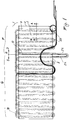
- the reference numeral 1 indicates the evaporator overall. It comprises a tube 2 (hereinafter known as the hairpin coil) bent to hairpin shape and comprising a series of approximately parallel rectilinear portions 2A connected together by curved portions or loops 2B. As taught in the aforementioned Italian patent application, the hairpin coil 2 is enclosed, preferably along only its rectilinear portions 2A, between two thin metal sheets 3 and 4, for example of aluminium of 0.15 mm thickness. The sheets 3 and 4 adhere to the tube 2 and to each other by virtue of the sheet 4 being provided with a layer of adhesive 6 which in Figure 2 is represented by a thicker line.
- the hairpin coil 2 bent to hairpin shape and comprising a series of approximately parallel rectilinear portions 2A connected together by curved portions or loops 2B.
- the hairpin coil 2 is enclosed, preferably along only its rectilinear portions 2A, between two thin metal sheets 3 and 4, for example of aluminium of 0.15 mm thickness.
- the sheets 3 and 4 adhere to the
- the sheet 4 is also provided with a layer of adhesive 7 on its outer face (this layer is also represented by a thicker line in Figure 2).
- the adhesive layer is protected by a repellent sheet 8 (for example of silicone-coated paper), which is removed when the evaporator is to be applied to the compartments of a refrigerator, it being fixed to the compartments by the adhesive layer 7.
- the evaporator of the invention serves for both the refrigeration compartment and the freezer compartment, notwithstanding the fact that it is in one piece in the sense that the relative hairpin coil has no discontinuities such as to require welding.
- the refrigeration compartment requires seven rectilinear portions 2A of the hairpin coil 2 and the freezer compartment requires seventeen rectilinear portions.
- the seven portions for the refrigeration compartment are those to the right D of the line R in Figure 1, the seventeen portions for the freezer compartment being those to the left S of the line R.
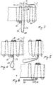
- the adjacent rectilinear hairpin coil portions are of greater length such as to project to a given extent from one side 3, 4 of the evaporator.
- a cut 10 is made through the sheets 3, 4 and 8 such as to separate them and hence obtain two evaporator sections, one F relative to the refrigeration compartment and the other G relative to the freezer compartment.
- the two portions 2'A are made to mutually overlie (as shown in Figure 4).
- the locators are positioned two on one edge and the other on the opposite edge of the sheets 3, 4, 8.
- the locator 20 is of circular cross-section and occupies the space between two connection loops 2B of the hairpin coil 2 on one side of the evaporator, the two locators 21, 22 being positioned on the other side of the evaporator to fix the position of the loops 2B relative to the portions 2'A when superposing these portions.
- the aforesaid operations can also be effected by hand, or my other means, including automatic means, different from those shown by way of example.
- the important aspects are the presence of two adjacent rectilinear portions 2'A of greater length projecting from one side of the evaporator, the cut (along R) separating the evaporator into two sections G and F, the approach and, preferably, the subsequent superposing of these unilaterally prolonged portions 2'A at least along that part of them sandwiched between the sheets 3 and 4 in proximity to the locator 20, and the bending of that part of said prolonged portions 2'A which projects external to the sheets so that it lies on one side of the evaporator approximately parallel to the rectilinear direction, followed by twisting these prolonged portions 2'A such that they finally lie in an ideal plane substantially perpendicular to said sections G and F.
- a syphon is formed which aids the refrigerator operation in that it ensures adequate filling of the freezer section G with the refrigerant fluid.
- the tube 2 can be of other than the circular cross-section shown, for example semi-circular or oval.
- the sections G and F can have a number of rectilinear, ie active, sections 2A different from the number shown in the example, depending on the refrigerator design.
- an electrical resistance element in the form of electrically insulated resistive wire
- This resistance element is indicated by 30 and is shown by dashed lines in Figure 1. It can involve either the entire hairpin coil 2 or alternatively only the freezer section G of the evaporator.
- Two resistance elements can however be provided, one for each of the evaporator sections G, F. In this latter case they can be powered either jointly or separately by switches or similar contactor means. For this purpose connecting the two sections of the resistance element in parallel and with a switch in each branch of the parallel connection is sufficient.
- both the capillary tube 77 and the terminal portion 78 of the hairpin coil 2 comprise a loop-shaped part 79 to facilitate the bending of the assembly.
- connection is simple to effect as a result of the "pre-shaping" of the evaporator to suitably fit the said compartment, the evaporator also comprising evaporator sections which although being different are connected together without any weld, the resultant evaporator hence being in one piece.
- At least one of the two sheets 3 and 4 is provided with a resistance element positioned such that it lies in proximity with the hairpin coil 2 after this has been placed on said sheet.
- the two portions of one and the same sheet 3 and 4 can be provided with resistance elements arranged to cooperate operationally with the sections G and F of the hairpin coil.
- freezer compartment indicates a compartment in which the product is preserved in the frozen state and/or can be brought into that state.
Landscapes
- Engineering & Computer Science (AREA)
- Physics & Mathematics (AREA)
- Mechanical Engineering (AREA)
- Thermal Sciences (AREA)
- General Engineering & Computer Science (AREA)
- Geometry (AREA)
- Devices That Are Associated With Refrigeration Equipment (AREA)
- Vaporization, Distillation, Condensation, Sublimation, And Cold Traps (AREA)
- Heat-Exchange Devices With Radiators And Conduit Assemblies (AREA)
- Dry Shavers And Clippers (AREA)
Applications Claiming Priority (2)
| Application Number | Priority Date | Filing Date | Title |
|---|---|---|---|
| ITMI972486 | 1997-11-06 | ||
| IT97MI002486A IT1296073B1 (it) | 1997-11-06 | 1997-11-06 | Metodo per ottenere un evaporatore monopezzo per circuiti frigorigeni ed evaporatore ottenuto |
Publications (3)
| Publication Number | Publication Date |
|---|---|
| EP0917919A2 true EP0917919A2 (de) | 1999-05-26 |
| EP0917919A3 EP0917919A3 (de) | 2001-04-11 |
| EP0917919B1 EP0917919B1 (de) | 2004-01-14 |
Family
ID=11378169
Family Applications (1)
| Application Number | Title | Priority Date | Filing Date |
|---|---|---|---|
| EP98119923A Expired - Lifetime EP0917919B1 (de) | 1997-11-06 | 1998-10-21 | Herstellungsverfahren eines einteiligen Verdampfers, und der hergestellte Verdampfer |
Country Status (6)
| Country | Link |
|---|---|
| EP (1) | EP0917919B1 (de) |
| AR (1) | AR017563A1 (de) |
| BR (1) | BR9804568A (de) |
| DE (1) | DE69821081T2 (de) |
| ES (1) | ES2212819T3 (de) |
| IT (1) | IT1296073B1 (de) |
Cited By (4)
| Publication number | Priority date | Publication date | Assignee | Title |
|---|---|---|---|---|
| EP1482258A1 (de) * | 2003-05-31 | 2004-12-01 | Lohmann GmbH & Co. KG | Rohrverdampfer sowie Verfahren und Vorrichtung für dessen Herstellung |
| RU2426038C2 (ru) * | 2006-04-05 | 2011-08-10 | Бсх Бош Унд Сименс Хаусгерете Гмбх | Холодильный аппарат с трубчатыми испарителями |
| EP2040015A3 (de) * | 2007-09-18 | 2015-03-04 | BSH Bosch und Siemens Hausgeräte GmbH | Kältegerät mit einer Verdampferanordnung und Herstellungsverfahren für die Verdampferanordnung |
| CN103438620B (zh) * | 2013-08-27 | 2016-01-06 | 海尔集团公司 | 高效蒸发器 |
Families Citing this family (3)
| Publication number | Priority date | Publication date | Assignee | Title |
|---|---|---|---|---|
| DE202005012048U1 (de) * | 2005-07-22 | 2006-12-07 | Liebherr-Hausgeräte Ochsenhausen GmbH | Rohr-/Blechverflüssiger für Kühl- und/oder Gefriergeräte |
| DE102016003547A1 (de) * | 2016-03-22 | 2017-09-28 | Liebherr-Hausgeräte Ochsenhausen GmbH | Kühl- und/oder Gefriergerät |
| DE102017211285A1 (de) * | 2017-07-03 | 2019-01-03 | BSH Hausgeräte GmbH | Kältegerät |
Citations (1)
| Publication number | Priority date | Publication date | Assignee | Title |
|---|---|---|---|---|
| ITMI960895A1 (it) | 1996-05-06 | 1997-11-06 | Whirlpool Europ S R L | Procedimento per ottenere evaporatori di circuiti frigorigeni ed evaporatore ottenuto |
Family Cites Families (5)
| Publication number | Priority date | Publication date | Assignee | Title |
|---|---|---|---|---|
| US1982075A (en) * | 1932-03-23 | 1934-11-27 | Fedders Mfg Co Inc | Method of making refrigerating apparatus |
| IT213782Z2 (it) * | 1988-05-04 | 1990-03-01 | Eurodomestici Ind Riunite | Evaporatore per frigoriferi statici. |
| JPH07109343B2 (ja) * | 1990-06-29 | 1995-11-22 | 昭和アルミニウム株式会社 | 冷凍・冷蔵庫用蒸発器 |
| DE19509571A1 (de) * | 1995-03-16 | 1996-09-19 | Bosch Siemens Hausgeraete | Verdampfer, insbesondere für kompressorbetriebene Haushalt-Kältegeräte |
| IT1289400B1 (it) * | 1996-11-26 | 1998-10-02 | Electrolux Zanussi Elettrodome | Metodo per produrre uno scambiatore di calore per un apparecchio refrigerante e scambiatore di calore cosi' prodotto |
-
1997
- 1997-11-06 IT IT97MI002486A patent/IT1296073B1/it active IP Right Grant
-
1998
- 1998-10-21 DE DE69821081T patent/DE69821081T2/de not_active Expired - Lifetime
- 1998-10-21 ES ES98119923T patent/ES2212819T3/es not_active Expired - Lifetime
- 1998-10-21 EP EP98119923A patent/EP0917919B1/de not_active Expired - Lifetime
- 1998-11-05 BR BR9804568-7A patent/BR9804568A/pt not_active IP Right Cessation
- 1998-11-05 AR ARP980105577A patent/AR017563A1/es active IP Right Grant
Patent Citations (1)
| Publication number | Priority date | Publication date | Assignee | Title |
|---|---|---|---|---|
| ITMI960895A1 (it) | 1996-05-06 | 1997-11-06 | Whirlpool Europ S R L | Procedimento per ottenere evaporatori di circuiti frigorigeni ed evaporatore ottenuto |
Cited By (4)
| Publication number | Priority date | Publication date | Assignee | Title |
|---|---|---|---|---|
| EP1482258A1 (de) * | 2003-05-31 | 2004-12-01 | Lohmann GmbH & Co. KG | Rohrverdampfer sowie Verfahren und Vorrichtung für dessen Herstellung |
| RU2426038C2 (ru) * | 2006-04-05 | 2011-08-10 | Бсх Бош Унд Сименс Хаусгерете Гмбх | Холодильный аппарат с трубчатыми испарителями |
| EP2040015A3 (de) * | 2007-09-18 | 2015-03-04 | BSH Bosch und Siemens Hausgeräte GmbH | Kältegerät mit einer Verdampferanordnung und Herstellungsverfahren für die Verdampferanordnung |
| CN103438620B (zh) * | 2013-08-27 | 2016-01-06 | 海尔集团公司 | 高效蒸发器 |
Also Published As
| Publication number | Publication date |
|---|---|
| AR017563A1 (es) | 2001-09-12 |
| IT1296073B1 (it) | 1999-06-09 |
| ES2212819T3 (es) | 2004-08-01 |
| ITMI972486A1 (it) | 1999-05-06 |
| DE69821081T2 (de) | 2004-11-11 |
| DE69821081D1 (de) | 2004-02-19 |
| EP0917919B1 (de) | 2004-01-14 |
| EP0917919A3 (de) | 2001-04-11 |
| BR9804568A (pt) | 2001-03-20 |
Similar Documents
| Publication | Publication Date | Title |
|---|---|---|
| EP0917919B1 (de) | Herstellungsverfahren eines einteiligen Verdampfers, und der hergestellte Verdampfer | |
| US4162571A (en) | Method of constructing refrigerator cabinet | |
| US4957451A (en) | Male electrical contact | |
| US5797451A (en) | Refrigeration apparatus | |
| US2691813A (en) | Method of constructing refrigeration evaporators | |
| US4267435A (en) | Electric resistance heating element | |
| US2823522A (en) | Evaporator constructed from extruded sections and method therefor | |
| TR200301052T1 (tr) | Defrost yöntemi ve bunu kullanan bir soğutma cihazı. | |
| US2077220A (en) | Freezing tray and method of making the same | |
| US2856163A (en) | Refrigerator condenser | |
| US2806360A (en) | Evaporator unit | |
| EP0844447A2 (de) | Verfahren zur Herstellung eines Wärmetauschers und damit hergestellter Wärmetauscher | |
| US5924292A (en) | Deodorizing element for eliminating refrigerator odors | |
| US2934917A (en) | Evaporator | |
| US1996808A (en) | Refrigerating apparatus | |
| TR27441A (tr) | Bilhassa sogutucularda veya dondurucularda bir raf evaporatörü olarak kullanilmak icin isi dönüstürücü. | |
| EP0464711A1 (de) | Verdampfer für Kühlschrank und Verfahren zu seiner Herstellung | |
| US2188781A (en) | Freezing tray | |
| US1991762A (en) | Refrigeration apparatus | |
| US3509608A (en) | Tab welded joint and method of making | |
| US20220146183A1 (en) | Refrigeration unit | |
| EP0364985B1 (de) | Verfahren zur Herstellung einer kombinierten Kühl- und Gefriervorrichtung | |
| GB2113489A (en) | Current-conducting parts for plug-in fuses | |
| KR0126858Y1 (ko) | 제상수단을 구비한 냉장고 냉기귀환덕트용 착상판 | |
| ES8506160A1 (es) | Perfeccionamientos en los serpentines de circulacion de fluidos refrigerantes |
Legal Events
| Date | Code | Title | Description |
|---|---|---|---|
| PUAI | Public reference made under article 153(3) epc to a published international application that has entered the european phase |
Free format text: ORIGINAL CODE: 0009012 |
|
| AK | Designated contracting states |
Kind code of ref document: A2 Designated state(s): DE ES FR GB IT |
|
| AX | Request for extension of the european patent |
Free format text: AL;LT;LV;MK;RO;SI |
|
| PUAL | Search report despatched |
Free format text: ORIGINAL CODE: 0009013 |
|
| AK | Designated contracting states |
Kind code of ref document: A3 Designated state(s): AT BE CH CY DE DK ES FI FR GB GR IE IT LI LU MC NL PT SE |
|
| AX | Request for extension of the european patent |
Free format text: AL;LT;LV;MK;RO;SI |
|
| 17P | Request for examination filed |
Effective date: 20011009 |
|
| AKX | Designation fees paid |
Free format text: DE ES FR GB IT |
|
| GRAP | Despatch of communication of intention to grant a patent |
Free format text: ORIGINAL CODE: EPIDOSNIGR1 |
|
| GRAS | Grant fee paid |
Free format text: ORIGINAL CODE: EPIDOSNIGR3 |
|
| GRAA | (expected) grant |
Free format text: ORIGINAL CODE: 0009210 |
|
| AK | Designated contracting states |
Kind code of ref document: B1 Designated state(s): DE ES FR GB IT |
|
| REG | Reference to a national code |
Ref country code: GB Ref legal event code: FG4D |
|
| REF | Corresponds to: |
Ref document number: 69821081 Country of ref document: DE Date of ref document: 20040219 Kind code of ref document: P |
|
| REG | Reference to a national code |
Ref country code: ES Ref legal event code: FG2A Ref document number: 2212819 Country of ref document: ES Kind code of ref document: T3 |
|
| ET | Fr: translation filed | ||
| PLBE | No opposition filed within time limit |
Free format text: ORIGINAL CODE: 0009261 |
|
| STAA | Information on the status of an ep patent application or granted ep patent |
Free format text: STATUS: NO OPPOSITION FILED WITHIN TIME LIMIT |
|
| 26N | No opposition filed |
Effective date: 20041015 |
|
| REG | Reference to a national code |
Ref country code: FR Ref legal event code: PLFP Year of fee payment: 19 |
|
| PGFP | Annual fee paid to national office [announced via postgrant information from national office to epo] |
Ref country code: FR Payment date: 20160919 Year of fee payment: 19 |
|
| PGFP | Annual fee paid to national office [announced via postgrant information from national office to epo] |
Ref country code: ES Payment date: 20160915 Year of fee payment: 19 |
|
| PGFP | Annual fee paid to national office [announced via postgrant information from national office to epo] |
Ref country code: GB Payment date: 20161019 Year of fee payment: 19 Ref country code: DE Payment date: 20161018 Year of fee payment: 19 |
|
| PGFP | Annual fee paid to national office [announced via postgrant information from national office to epo] |
Ref country code: IT Payment date: 20161024 Year of fee payment: 19 |
|
| REG | Reference to a national code |
Ref country code: DE Ref legal event code: R119 Ref document number: 69821081 Country of ref document: DE |
|
| GBPC | Gb: european patent ceased through non-payment of renewal fee |
Effective date: 20171021 |
|
| REG | Reference to a national code |
Ref country code: FR Ref legal event code: ST Effective date: 20180629 |
|
| PG25 | Lapsed in a contracting state [announced via postgrant information from national office to epo] |
Ref country code: DE Free format text: LAPSE BECAUSE OF NON-PAYMENT OF DUE FEES Effective date: 20180501 Ref country code: GB Free format text: LAPSE BECAUSE OF NON-PAYMENT OF DUE FEES Effective date: 20171021 |
|
| PG25 | Lapsed in a contracting state [announced via postgrant information from national office to epo] |
Ref country code: FR Free format text: LAPSE BECAUSE OF NON-PAYMENT OF DUE FEES Effective date: 20171031 |
|
| PG25 | Lapsed in a contracting state [announced via postgrant information from national office to epo] |
Ref country code: IT Free format text: LAPSE BECAUSE OF NON-PAYMENT OF DUE FEES Effective date: 20171021 |
|
| REG | Reference to a national code |
Ref country code: ES Ref legal event code: FD2A Effective date: 20181221 |
|
| PG25 | Lapsed in a contracting state [announced via postgrant information from national office to epo] |
Ref country code: ES Free format text: LAPSE BECAUSE OF NON-PAYMENT OF DUE FEES Effective date: 20171022 |