EP0918008B1 - Drehgestell mit einer Neigevorrichtung - Google Patents
Drehgestell mit einer Neigevorrichtung Download PDFInfo
- Publication number
- EP0918008B1 EP0918008B1 EP98402862A EP98402862A EP0918008B1 EP 0918008 B1 EP0918008 B1 EP 0918008B1 EP 98402862 A EP98402862 A EP 98402862A EP 98402862 A EP98402862 A EP 98402862A EP 0918008 B1 EP0918008 B1 EP 0918008B1
- Authority
- EP
- European Patent Office
- Prior art keywords
- bogie
- tilting
- transverse bar
- control
- vehicle
- Prior art date
- Legal status (The legal status is an assumption and is not a legal conclusion. Google has not performed a legal analysis and makes no representation as to the accuracy of the status listed.)
- Expired - Lifetime
Links
Images



Classifications
-
- B—PERFORMING OPERATIONS; TRANSPORTING
- B61—RAILWAYS
- B61F—RAIL VEHICLE SUSPENSIONS, e.g. UNDERFRAMES, BOGIES OR ARRANGEMENTS OF WHEEL AXLES; RAIL VEHICLES FOR USE ON TRACKS OF DIFFERENT WIDTH; PREVENTING DERAILING OF RAIL VEHICLES; WHEEL GUARDS, OBSTRUCTION REMOVERS OR THE LIKE FOR RAIL VEHICLES
- B61F5/00—Constructional details of bogies; Connections between bogies and vehicle underframes; Arrangements or devices for adjusting or allowing self-adjustment of wheel axles or bogies when rounding curves
- B61F5/02—Arrangements permitting limited transverse relative movements between vehicle underframe or bolster and bogie; Connections between underframes and bogies
- B61F5/22—Guiding of the vehicle underframes with respect to the bogies
Definitions
- the present invention relates to vehicles whose bogies compensate for cant deficiency, in general, and bears, more particularly, on a tilting device with jacks, and on a tilting bogie with cylinders.
- EP 0 189 382 relates to links between bogies and chassis of a railway vehicle.
- FIG. 5 of this document of the prior art shows a vehicle the bogie provides for pendular compensation of slope failures by the application of a gutter angle to a sleeper tilt and thus to the vehicle body.
- This pendulum compensation is obtained by means of a tilting device with connecting rods.
- the rod tilting device of the art front includes a tilting crossbar arranged in a frame of bogie and suspended by means of connecting rods.
- the tilting movement between the tilting crossbar and the bogie frame is obtained because of the presence of ball joints at each ends of the connecting rods.
- suspensions are arranged between the bogie frame and the boxes axles, and secondary suspensions are arranged between the beam tilt and the vehicle body.
- a disadvantage of the tilting device of the prior art is the lack of free volume in the central part of the bogie.
- DE-37 11 907 discloses a tilting bogie according to the preamble of claim 1.
- a tilting cross member connects the ends upper control cylinders of the tilting.
- Such a tilting bogie also has the disadvantages of lack of free volume in its central part, and its weight and cost high.
- an object of the invention is there a tilting bogie not not having the disadvantages of tilting bogies of the prior art.
- the invention relates to a tilting bogie according to claim 1.
- the tilting device of the invention can also include one or more of the features of the dependent claims.
- An advantage of the tilting bogie of the invention is a gain mass of the order of 300 to 500 kg per truck.
- tilting bogie of the invention is to allow a leveling of cars compared to the platforms by regulation the position of the control cylinders.
- the invention also relates to a vehicle according to the claim 9.
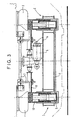
- Figures 1 to 3 are views, respectively, lateral, of top and partially sectioned side of the tilting device according to a first embodiment according to the invention, in which a bar antiroll is placed under the body.
- Figures 4 to 6 are views, respectively, lateral, of top and partially sectioned side of the tilting device according to a second embodiment according to the invention, in which a bar antiroulis is connected to be secured to the support feet of the suspension secondary.
- the tilting device for a bogie has a first 1 and a second 2 tilt control cylinders arranged rigidly and vertically in the bogie, in which they are housed.
- This bogie comprises a chassis 6 having, seen from above, a H-shaped, with a central cross member and two side rails extending respectively to both ends of the crossbar, forward and behind this one.
- the two control cylinders 1, 2 are housed in the chassis in the connection regions of the longitudinal members to the cross-member, and, as they are rigidly arranged in the bogie, their longitudinal axis can not rotate relative to the plane in which the H of the bogie extends.
- the secondary suspensions 3 are arranged under the body 4 of the vehicle, which rests on them, and rest themselves on the cylinders tilt control 1, 2, for example via support feet 8.
- the chassis 6 comprises, in the regions of connection of the beams to the cross member, a housing approximately cylindrical extending substantially vertically when the vehicle rests on an approximately horizontal ground as shown on the drawings; cylinder cylinders, positioned in these housing, telescopically actuate the supporting feet 8 on which the secondary suspensions on which is placed the vehicle.
- the inclination of the vehicle body is obtained under the action tilt control cylinders 1, 2, while retaining suspensions 3 flexible secondary by means of a refocusing cylinder 5 arranged in the central region of the bogie.
- the refocusing cylinder 5 is connected by one of its ends to the bogie frame 6 at one point of the crossbar slightly off-center laterally and longitudinally, and through the other of its ends to the crate 4 the vehicle at a point also slightly off-center, laterally opposite side.
- An anti-roll bar 7 is disposed under the body 4.
- the anti-roll bar 7 has a transverse bar and two connecting rods extending approximately vertically when the vehicle is on a horizontal floor as shown in the drawings, one of the ends connecting rods being connected to the crossbar.
- the crossbar the anti-roll bar is arranged under the box 4 while being connected to the bottom face of the latter by bearings, and the connecting rods are arranged, by their free ends, at the bottom of the secondary suspensions 3, for example on the support legs 8 of the secondary suspensions ; more specifically, the connecting rods extend approximately vertically downwards from their end connected or secured to the bar transverse and towards their opposite end; it is this end opposite (called “free") connecting rods which is connected to the support feet.
- the crossbar is arranged at the bottom of the secondary suspensions 3, by example on or under the support feet 8 of the secondary suspensions in being connected to these by a respective support, and the vertical rods are arranged, by their free ends, under the body 4; more precisely, the connecting rods extend approximately vertically upwards since their end secured to the crossbar and going towards their end opposite; it is this opposite end (called “free") of the connecting rods which is secured to the base of the box.
- control cylinders 1, 2 of the tilting are preferably either hydraulically controlled, either electromechanically controlled.
- An advantage of the hydraulic connection 11 between the chambers 9 of the control cylinders 1, 2 is that at the station stop it is possible to upgrade cars relative to the wharf by regulating the pressure in the lower chambers 9 of the control cylinders 1, 2.
- the bogie ensures a pendulum compensation of the deficiencies of cant by the application of an angle of shelter by putting in pressure the superior room 10 of one of the control cylinders of the tilt 1, 2.
- the present invention also relates to a tilting bogie comprising a tilting device as described above.
Landscapes
- Engineering & Computer Science (AREA)
- Mechanical Engineering (AREA)
- Vehicle Body Suspensions (AREA)
- Treatments For Attaching Organic Compounds To Fibrous Goods (AREA)
- Push-Button Switches (AREA)
- Devices For Checking Fares Or Tickets At Control Points (AREA)
Claims (9)
- Neigedrehgestell eines Wagenkastens (4), wobei das Drehgestell einen Rahmen (6), ein erstes (1) und ein zweites (2) Stellglied zur Neigesteuerung, die in dem Rahmen angeordnet sind, Sekundärfederungen (3), die dazu bestimmt sind, unter dem Wagenkasten (4) angeordnet zu sein, und auf den Stellgliedern (1, 2) zur Neigesteuerung aufliegen, und ein Rezentrierungs-Stellglied (5) aufweist, das über eines seiner Enden mit dem Drehgestellrahmen (6) verbunden ist und dazu bestimmt ist, über das andere seiner Enden mit dem Wagenkasten (4) verbunden zu werden, dadurch gekennzeichnet, daß das erste und das zweite Stellglied zur Neigesteuerung starr und vertikal in dem Rahmen angeordnet sind und daß das Drehgestell weder eine Neigungstraverse noch Stangen zur Aufhängung der Neigungstraverse aufweist.
- Drehgestell nach Anspruch 1, dadurch gekennzeichnet, daß, das Drehgestell eine Rollstabilisierungsstange (7) aufweist, die unter dem Kasten (4) angeordnet ist.
- Drehgestell nach Anspruch 2, bei dem die Rollstabilisierungsstange (7) eine Querstange und zwei Stangen aufweist, die sich annähernd vertikal erstrecken und von denen ein Ende mit der Querstange verbunden oder an dieser befestigt ist, wobei diese Querstange dazu bestimmt ist, unter dem Kasten (4) angeordnet zu werden, und die Stangen sich von ihrem mit der Querstange verbundenen oder an dieser befestigten Ende aus bis zu ihrem entgegengesetzten Ende im unteren Teil der Sekundärfederungen (3) erstrecken.
- Drehgestell nach Anspruch 2, bei dem die Rollstabilisierungsstange (7) eine Querstange und zwei Stangen aufweist, die sich annähernd vertikal erstrecken und von denen ein Ende mit der Querstange verbunden oder an dieser befestigt ist, wobei diese Querstange im unteren Teil der Sekundärfederungen (3) angeordnet ist und die Stangen sich von ihrem mit der Querstange verbundenen oder an dieser befestigten Ende aus bis zu ihrem entgegengesetzten Ende unter dem Kasten (4) erstrecken.
- Drehgestell nach einem der Ansprüche 1 bis 4, bei dem die Stellglieder (1, 2) zur Neigesteuerung hydraulisch gesteuert sind.
- Drehgestell nach Anspruch 5, bei dem die unteren Kammern (9) der Stellglieder (1, 2) mit Hilfe einer hydraulischen Verbindung (11) verbunden sind.
- Drehgestell nach einem der Ansprüche 1 bis 4, bei dem die Stellglieder (1, 2) zur Neigesteuerung elektromechanisch gesteuert sind.
- Drehgestell nach einem der Ansprüche 1 bis 7, bei dem die Sekundärfederungen (3) einen Stützfuß (8) aufweisen.
- Fahrzeug, dadurch gekennzeichnet, daß es ein Drehgestell nach einem der vorhergehenden Ansprüche aufweist.
Applications Claiming Priority (2)
| Application Number | Priority Date | Filing Date | Title |
|---|---|---|---|
| FR9714565 | 1997-11-20 | ||
| FR9714565A FR2771065B1 (fr) | 1997-11-20 | 1997-11-20 | Dispositif de pendulation a verins et bogie a pendulation a verins |
Publications (2)
| Publication Number | Publication Date |
|---|---|
| EP0918008A1 EP0918008A1 (de) | 1999-05-26 |
| EP0918008B1 true EP0918008B1 (de) | 2005-01-26 |
Family
ID=9513585
Family Applications (1)
| Application Number | Title | Priority Date | Filing Date |
|---|---|---|---|
| EP98402862A Expired - Lifetime EP0918008B1 (de) | 1997-11-20 | 1998-11-18 | Drehgestell mit einer Neigevorrichtung |
Country Status (8)
| Country | Link |
|---|---|
| US (1) | US6199875B1 (de) |
| EP (1) | EP0918008B1 (de) |
| AT (1) | ATE287814T1 (de) |
| CA (1) | CA2252047C (de) |
| DE (1) | DE69828742T2 (de) |
| ES (1) | ES2241108T3 (de) |
| FR (1) | FR2771065B1 (de) |
| PT (1) | PT918008E (de) |
Families Citing this family (6)
| Publication number | Priority date | Publication date | Assignee | Title |
|---|---|---|---|---|
| US6622635B2 (en) | 1998-01-12 | 2003-09-23 | Autran Corp. | Automated transportation system |
| RU2174476C1 (ru) * | 2000-03-16 | 2001-10-10 | Акционерное общество "Крюковский вагоностроительный завод" | Тележка грузового вагона |
| AU2003203695A1 (en) * | 2003-04-15 | 2004-11-04 | Downer Edi Limited | Bogie |
| KR100623202B1 (ko) | 2005-11-01 | 2006-09-13 | Stx조선주식회사 | 대형 구조물 이송장치 및 이송방법 |
| FR3051171B1 (fr) * | 2016-05-10 | 2019-05-03 | Alstom Transport Technologies | Palier de montage d'une barre antiroulis sur un chassis de bogie, et bogie correspondant |
| CN106364516A (zh) * | 2016-10-21 | 2017-02-01 | 中车株洲电力机车有限公司 | 一种城轨列车抗侧滚装置、城轨列车转向架及该城轨列车 |
Family Cites Families (8)
| Publication number | Priority date | Publication date | Assignee | Title |
|---|---|---|---|---|
| US4069767A (en) * | 1972-11-08 | 1978-01-24 | Lucas Aerospace | Pneumatically controlled hydromechanical railway car stabilizing apparatus |
| SE509153C2 (sv) * | 1995-11-07 | 1998-12-07 | Const Y Aux Ferrocarriles Sa | Lutningssystem för järnvägsvagnar |
| IT1183754B (it) | 1985-01-18 | 1987-10-22 | Fiat Ferroviaria Savigliano | Veicolo ferroviario per alte velocita con cassa ad assetto variabile |
| DE3711907A1 (de) * | 1987-04-08 | 1988-11-10 | Gutehoffnungshuette Man | Gleisbogenabhaengige wagenkastenneigungssteuerung fuer luftfeder-drehgestelle |
| DE3719990A1 (de) | 1987-06-15 | 1988-12-29 | Hoechst Ag | Verkapselte ativchlortraeger auf basis von dichlorisocyanursaeure sowie ein verfahren zur herstellung dieser produkte |
| US5255611A (en) * | 1988-10-13 | 1993-10-26 | Sig Schweizerische Industrie-Gesellschaft | Tilt compensator for high-speed vehicles, in particular rail vehicles |
| DE4241929A1 (de) * | 1992-12-11 | 1994-06-16 | Rexroth Mannesmann Gmbh | Aufhängung für einen Wagenkasten an einem Fahrgestell, insbesondere an einem Drehgestell eines schienengebundenen Fahrzeugs |
| IT1280854B1 (it) * | 1995-04-07 | 1998-02-11 | Fiat Ferroviaria Spa | "veicolo ferroviario con cassa ad assetto variabile" |
-
1997
- 1997-11-20 FR FR9714565A patent/FR2771065B1/fr not_active Expired - Lifetime
-
1998
- 1998-09-30 US US09/163,157 patent/US6199875B1/en not_active Expired - Lifetime
- 1998-11-18 EP EP98402862A patent/EP0918008B1/de not_active Expired - Lifetime
- 1998-11-18 PT PT98402862T patent/PT918008E/pt unknown
- 1998-11-18 DE DE69828742T patent/DE69828742T2/de not_active Expired - Lifetime
- 1998-11-18 AT AT98402862T patent/ATE287814T1/de active
- 1998-11-18 ES ES98402862T patent/ES2241108T3/es not_active Expired - Lifetime
- 1998-11-19 CA CA002252047A patent/CA2252047C/fr not_active Expired - Lifetime
Also Published As
| Publication number | Publication date |
|---|---|
| DE69828742T2 (de) | 2005-06-30 |
| FR2771065A1 (fr) | 1999-05-21 |
| CA2252047A1 (fr) | 1999-05-20 |
| EP0918008A1 (de) | 1999-05-26 |
| ATE287814T1 (de) | 2005-02-15 |
| CA2252047C (fr) | 2005-06-14 |
| FR2771065B1 (fr) | 2003-04-18 |
| PT918008E (pt) | 2005-05-31 |
| DE69828742D1 (de) | 2005-03-03 |
| ES2241108T3 (es) | 2005-10-16 |
| US6199875B1 (en) | 2001-03-13 |
Similar Documents
| Publication | Publication Date | Title |
|---|---|---|
| US5039124A (en) | Motor vehicle frame and suspension assembly | |
| US4000913A (en) | Lightweight high strength auxiliary lift axle suspension system for high framed vehicles | |
| CA2307610C (en) | A lifting device with a liftable and tiltable platform | |
| AU2001264586B2 (en) | Front axle air suspension | |
| US10683046B2 (en) | Tandem lift auxiliary axle assembly | |
| RU99120993A (ru) | Железнодорожный терминал для контейнеров и железнодорожная вагон-платформа | |
| CA2252047C (fr) | Dispositif de pendulation a verins, et bogie a pendulation a verins | |
| FR2693278A1 (fr) | Dispositif comportant un vibrateur fixé à un véhicule pour produire des vibrations sismiques. | |
| US6382659B1 (en) | Load distributing tandem suspension assembly | |
| US5476274A (en) | Platform elevating vehicle suspension | |
| US5184872A (en) | Dumping semi-trailer | |
| EP0991560A1 (de) | Vorrichtung zum hochheben der achse eines fahrzeuges | |
| EP0162511A1 (de) | Fahrzeug mit unabhängiger Luftaufhängung einer Achseneinheit und Achseneinheit | |
| US6935668B1 (en) | A-frame mounted on a flat bed trailer | |
| EP1162092A3 (de) | Fahrzeugaufhängung mit zwei lenkbare Räder tragender Achse, insbesondere für Vierrad-Gabelstapler | |
| EP1132248A3 (de) | Aufhängevorrichtung für einen Tank | |
| CA2220025C (fr) | Dispositif de pendulation a bielles et bogie a pendulation a bielles | |
| RU2569152C2 (ru) | Способ и устройство на грузовых автомобилях для опрокидывания грузового бункера | |
| CA2232511C (en) | Axle construction for a vehicle | |
| JPS60163742A (ja) | ダンプ荷降し時の車体安定装置 | |
| FI57716B (fi) | Stabiliserande anordning vid terraengfordon (t ex larvkaettingstraktor) | |
| US4128275A (en) | Tipping vehicle | |
| EP0142589A1 (de) | Aufliegeranhänger für Huckepackverkehr | |
| GB2225986A (en) | Vehicle suspension | |
| GB2253195A (en) | Vehicle supports |
Legal Events
| Date | Code | Title | Description |
|---|---|---|---|
| PUAI | Public reference made under article 153(3) epc to a published international application that has entered the european phase |
Free format text: ORIGINAL CODE: 0009012 |
|
| AK | Designated contracting states |
Kind code of ref document: A1 Designated state(s): AT BE CH DE ES FR GB IT LI NL PT |
|
| AX | Request for extension of the european patent |
Free format text: AL;LT;LV;MK;RO;SI |
|
| 17P | Request for examination filed |
Effective date: 19990607 |
|
| RAP3 | Party data changed (applicant data changed or rights of an application transferred) |
Owner name: ALSTOM TRANSPORT S.A. |
|
| AKX | Designation fees paid |
Free format text: AT BE CH DE ES FR GB IT LI NL PT |
|
| 17Q | First examination report despatched |
Effective date: 20020610 |
|
| RTI1 | Title (correction) |
Free format text: BOGIE WITH A TILTING DEVICE |
|
| GRAP | Despatch of communication of intention to grant a patent |
Free format text: ORIGINAL CODE: EPIDOSNIGR1 |
|
| RTI1 | Title (correction) |
Free format text: BOGIE WITH A TILTING DEVICE |
|
| GRAS | Grant fee paid |
Free format text: ORIGINAL CODE: EPIDOSNIGR3 |
|
| GRAA | (expected) grant |
Free format text: ORIGINAL CODE: 0009210 |
|
| AK | Designated contracting states |
Kind code of ref document: B1 Designated state(s): AT BE CH DE ES FR GB IT LI NL PT |
|
| REG | Reference to a national code |
Ref country code: GB Ref legal event code: FG4D Free format text: NOT ENGLISH |
|
| REG | Reference to a national code |
Ref country code: CH Ref legal event code: EP |
|
| REF | Corresponds to: |
Ref document number: 69828742 Country of ref document: DE Date of ref document: 20050303 Kind code of ref document: P |
|
| GBT | Gb: translation of ep patent filed (gb section 77(6)(a)/1977) |
Effective date: 20050330 |
|
| REG | Reference to a national code |
Ref country code: PT Ref legal event code: SC4A Free format text: AVAILABILITY OF NATIONAL TRANSLATION Effective date: 20050323 |
|
| REG | Reference to a national code |
Ref country code: ES Ref legal event code: FG2A Ref document number: 2241108 Country of ref document: ES Kind code of ref document: T3 |
|
| PLBE | No opposition filed within time limit |
Free format text: ORIGINAL CODE: 0009261 |
|
| STAA | Information on the status of an ep patent application or granted ep patent |
Free format text: STATUS: NO OPPOSITION FILED WITHIN TIME LIMIT |
|
| 26N | No opposition filed |
Effective date: 20051027 |
|
| REG | Reference to a national code |
Ref country code: FR Ref legal event code: TP Owner name: ALSTOM TRANSPORT TECHNOLOGIES, FR Effective date: 20141209 |
|
| REG | Reference to a national code |
Ref country code: CH Ref legal event code: PUE Owner name: ALSTOM TRANSPORT TECHNOLOGIES, FR Free format text: FORMER OWNER: ALSTOM TRANSPORT S.A., FR |
|
| REG | Reference to a national code |
Ref country code: DE Ref legal event code: R082 Ref document number: 69828742 Country of ref document: DE Representative=s name: MANITZ FINSTERWALD PATENTANWAELTE PARTMBB, DE Ref country code: DE Ref legal event code: R082 Ref document number: 69828742 Country of ref document: DE Representative=s name: MANITZ, FINSTERWALD & PARTNER GBR, DE Ref country code: DE Ref legal event code: R081 Ref document number: 69828742 Country of ref document: DE Owner name: ALSTOM TRANSPORT TECHNOLOGIES, FR Free format text: FORMER OWNER: ALSTOM TRANSPORT S.A., PARIS, FR |
|
| REG | Reference to a national code |
Ref country code: PT Ref legal event code: PC4A Owner name: ALSTOM TRANSPORT TECHNOLOGIES, FR Effective date: 20150929 |
|
| REG | Reference to a national code |
Ref country code: FR Ref legal event code: PLFP Year of fee payment: 18 |
|
| REG | Reference to a national code |
Ref country code: GB Ref legal event code: 732E Free format text: REGISTERED BETWEEN 20151126 AND 20151202 |
|
| REG | Reference to a national code |
Ref country code: FR Ref legal event code: PLFP Year of fee payment: 19 |
|
| REG | Reference to a national code |
Ref country code: DE Ref legal event code: R082 Ref document number: 69828742 Country of ref document: DE Representative=s name: MANITZ FINSTERWALD PATENTANWAELTE PARTMBB, DE Ref country code: DE Ref legal event code: R081 Ref document number: 69828742 Country of ref document: DE Owner name: ALSTOM TRANSPORT TECHNOLOGIES, FR Free format text: FORMER OWNER: ALSTOM TRANSPORT TECHNOLOGIES, LEVALLOIS-PERRET, FR |
|
| REG | Reference to a national code |
Ref country code: CH Ref legal event code: PCOW Free format text: NEW ADDRESS: 48 RUE ALBERT DHALENNE, 93400 SAINT-OUEN (FR) Ref country code: CH Ref legal event code: NV Representative=s name: BUGNION S.A., CH |
|
| REG | Reference to a national code |
Ref country code: FR Ref legal event code: PLFP Year of fee payment: 20 |
|
| PGFP | Annual fee paid to national office [announced via postgrant information from national office to epo] |
Ref country code: NL Payment date: 20171120 Year of fee payment: 20 Ref country code: FR Payment date: 20171121 Year of fee payment: 20 Ref country code: DE Payment date: 20171121 Year of fee payment: 20 |
|
| REG | Reference to a national code |
Ref country code: FR Ref legal event code: CA Effective date: 20180103 |
|
| PGFP | Annual fee paid to national office [announced via postgrant information from national office to epo] |
Ref country code: AT Payment date: 20171121 Year of fee payment: 20 Ref country code: IT Payment date: 20171124 Year of fee payment: 20 Ref country code: PT Payment date: 20171116 Year of fee payment: 20 Ref country code: CH Payment date: 20171120 Year of fee payment: 20 Ref country code: GB Payment date: 20171123 Year of fee payment: 20 Ref country code: ES Payment date: 20171220 Year of fee payment: 20 Ref country code: BE Payment date: 20171120 Year of fee payment: 20 |
|
| REG | Reference to a national code |
Ref country code: AT Ref legal event code: PC Ref document number: 287814 Country of ref document: AT Kind code of ref document: T Owner name: ALSTOM TRANSPORT TECHNOLOGIES, FR Effective date: 20180220 |
|
| REG | Reference to a national code |
Ref country code: DE Ref legal event code: R071 Ref document number: 69828742 Country of ref document: DE |
|
| REG | Reference to a national code |
Ref country code: NL Ref legal event code: MK Effective date: 20181117 |
|
| REG | Reference to a national code |
Ref country code: CH Ref legal event code: PL |
|
| REG | Reference to a national code |
Ref country code: GB Ref legal event code: PE20 Expiry date: 20181117 |
|
| REG | Reference to a national code |
Ref country code: BE Ref legal event code: PD Owner name: ALSTOM TRANSPORT TECHNOLOGIES SAS; FR Free format text: DETAILS ASSIGNMENT: CHANGE OF OWNER(S), AFFECTATION / CESSION; FORMER OWNER NAME: ALSTOM TRANSPORT S.A. Effective date: 20150423 Ref country code: BE Ref legal event code: MK Effective date: 20181118 |
|
| REG | Reference to a national code |
Ref country code: AT Ref legal event code: MK07 Ref document number: 287814 Country of ref document: AT Kind code of ref document: T Effective date: 20181118 |
|
| PG25 | Lapsed in a contracting state [announced via postgrant information from national office to epo] |
Ref country code: PT Free format text: LAPSE BECAUSE OF EXPIRATION OF PROTECTION Effective date: 20181127 |
|
| PG25 | Lapsed in a contracting state [announced via postgrant information from national office to epo] |
Ref country code: GB Free format text: LAPSE BECAUSE OF EXPIRATION OF PROTECTION Effective date: 20181117 |
|
| REG | Reference to a national code |
Ref country code: ES Ref legal event code: FD2A Effective date: 20200804 |
|
| PG25 | Lapsed in a contracting state [announced via postgrant information from national office to epo] |
Ref country code: ES Free format text: LAPSE BECAUSE OF EXPIRATION OF PROTECTION Effective date: 20181119 |
|
| REG | Reference to a national code |
Ref country code: ES Ref legal event code: PC2A Owner name: ALSTOM TRANSPORT TECHNOLOGIES Effective date: 20210601 |