EP0918119A2 - Stein- und/oder Glass-Verbund-element mit Hinterschnittdübel - Google Patents
Stein- und/oder Glass-Verbund-element mit Hinterschnittdübel Download PDFInfo
- Publication number
- EP0918119A2 EP0918119A2 EP98118909A EP98118909A EP0918119A2 EP 0918119 A2 EP0918119 A2 EP 0918119A2 EP 98118909 A EP98118909 A EP 98118909A EP 98118909 A EP98118909 A EP 98118909A EP 0918119 A2 EP0918119 A2 EP 0918119A2
- Authority
- EP
- European Patent Office
- Prior art keywords
- panel assembly
- intermediate layer
- sleeve
- assembly according
- layer
- Prior art date
- Legal status (The legal status is an assumption and is not a legal conclusion. Google has not performed a legal analysis and makes no representation as to the accuracy of the status listed.)
- Granted
Links
- 239000002131 composite material Substances 0.000 title claims abstract description 30
- 239000011521 glass Substances 0.000 claims description 22
- 229920003023 plastic Polymers 0.000 claims description 11
- 239000004575 stone Substances 0.000 claims description 11
- 239000002184 metal Substances 0.000 claims description 9
- 239000000463 material Substances 0.000 claims description 5
- 239000011347 resin Substances 0.000 claims description 4
- 229920005989 resin Polymers 0.000 claims description 4
- 229910000831 Steel Inorganic materials 0.000 claims description 3
- 239000002313 adhesive film Substances 0.000 claims description 3
- 229910044991 metal oxide Inorganic materials 0.000 claims description 3
- 150000004706 metal oxides Chemical class 0.000 claims description 3
- 238000002161 passivation Methods 0.000 claims description 3
- 239000006223 plastic coating Substances 0.000 claims description 3
- 239000010959 steel Substances 0.000 claims description 3
- 230000009972 noncorrosive effect Effects 0.000 claims description 2
- 239000011248 coating agent Substances 0.000 description 4
- 238000000576 coating method Methods 0.000 description 4
- 238000011161 development Methods 0.000 description 4
- 230000018109 developmental process Effects 0.000 description 4
- 238000004519 manufacturing process Methods 0.000 description 3
- 238000003892 spreading Methods 0.000 description 3
- 238000009435 building construction Methods 0.000 description 2
- 230000002349 favourable effect Effects 0.000 description 2
- 239000005341 toughened glass Substances 0.000 description 2
- 235000001674 Agaricus brunnescens Nutrition 0.000 description 1
- 241000209035 Ilex Species 0.000 description 1
- 206010041662 Splinter Diseases 0.000 description 1
- 238000010521 absorption reaction Methods 0.000 description 1
- 239000000853 adhesive Substances 0.000 description 1
- 230000001070 adhesive effect Effects 0.000 description 1
- 239000002969 artificial stone Substances 0.000 description 1
- 230000005540 biological transmission Effects 0.000 description 1
- 239000012876 carrier material Substances 0.000 description 1
- 238000005253 cladding Methods 0.000 description 1
- 230000006378 damage Effects 0.000 description 1
- 230000006735 deficit Effects 0.000 description 1
- 238000009826 distribution Methods 0.000 description 1
- 238000005516 engineering process Methods 0.000 description 1
- 239000005329 float glass Substances 0.000 description 1
- 238000013467 fragmentation Methods 0.000 description 1
- 238000006062 fragmentation reaction Methods 0.000 description 1
- 238000009434 installation Methods 0.000 description 1
- 238000007740 vapor deposition Methods 0.000 description 1
Images
Classifications
-
- B—PERFORMING OPERATIONS; TRANSPORTING
- B32—LAYERED PRODUCTS
- B32B—LAYERED PRODUCTS, i.e. PRODUCTS BUILT-UP OF STRATA OF FLAT OR NON-FLAT, e.g. CELLULAR OR HONEYCOMB, FORM
- B32B17/00—Layered products essentially comprising sheet glass, or glass, slag, or like fibres
- B32B17/06—Layered products essentially comprising sheet glass, or glass, slag, or like fibres comprising glass as the main or only constituent of a layer, next to another layer of a specific material
- B32B17/10—Layered products essentially comprising sheet glass, or glass, slag, or like fibres comprising glass as the main or only constituent of a layer, next to another layer of a specific material of synthetic resin
- B32B17/10005—Layered products essentially comprising sheet glass, or glass, slag, or like fibres comprising glass as the main or only constituent of a layer, next to another layer of a specific material of synthetic resin laminated safety glass or glazing
- B32B17/10165—Functional features of the laminated safety glass or glazing
- B32B17/10293—Edge features, e.g. inserts or holes
-
- B—PERFORMING OPERATIONS; TRANSPORTING
- B32—LAYERED PRODUCTS
- B32B—LAYERED PRODUCTS, i.e. PRODUCTS BUILT-UP OF STRATA OF FLAT OR NON-FLAT, e.g. CELLULAR OR HONEYCOMB, FORM
- B32B17/00—Layered products essentially comprising sheet glass, or glass, slag, or like fibres
- B32B17/06—Layered products essentially comprising sheet glass, or glass, slag, or like fibres comprising glass as the main or only constituent of a layer, next to another layer of a specific material
-
- B—PERFORMING OPERATIONS; TRANSPORTING
- B32—LAYERED PRODUCTS
- B32B—LAYERED PRODUCTS, i.e. PRODUCTS BUILT-UP OF STRATA OF FLAT OR NON-FLAT, e.g. CELLULAR OR HONEYCOMB, FORM
- B32B17/00—Layered products essentially comprising sheet glass, or glass, slag, or like fibres
- B32B17/06—Layered products essentially comprising sheet glass, or glass, slag, or like fibres comprising glass as the main or only constituent of a layer, next to another layer of a specific material
- B32B17/10—Layered products essentially comprising sheet glass, or glass, slag, or like fibres comprising glass as the main or only constituent of a layer, next to another layer of a specific material of synthetic resin
- B32B17/10005—Layered products essentially comprising sheet glass, or glass, slag, or like fibres comprising glass as the main or only constituent of a layer, next to another layer of a specific material of synthetic resin laminated safety glass or glazing
- B32B17/10009—Layered products essentially comprising sheet glass, or glass, slag, or like fibres comprising glass as the main or only constituent of a layer, next to another layer of a specific material of synthetic resin laminated safety glass or glazing characterized by the number, the constitution or treatment of glass sheets
- B32B17/10036—Layered products essentially comprising sheet glass, or glass, slag, or like fibres comprising glass as the main or only constituent of a layer, next to another layer of a specific material of synthetic resin laminated safety glass or glazing characterized by the number, the constitution or treatment of glass sheets comprising two outer glass sheets
-
- B—PERFORMING OPERATIONS; TRANSPORTING
- B32—LAYERED PRODUCTS
- B32B—LAYERED PRODUCTS, i.e. PRODUCTS BUILT-UP OF STRATA OF FLAT OR NON-FLAT, e.g. CELLULAR OR HONEYCOMB, FORM
- B32B9/00—Layered products comprising a layer of a particular substance not covered by groups B32B11/00 - B32B29/00
- B32B9/04—Layered products comprising a layer of a particular substance not covered by groups B32B11/00 - B32B29/00 comprising such particular substance as the main or only constituent of a layer, which is next to another layer of the same or of a different material
-
- E—FIXED CONSTRUCTIONS
- E04—BUILDING
- E04F—FINISHING WORK ON BUILDINGS, e.g. STAIRS, FLOORS
- E04F13/00—Coverings or linings, e.g. for walls or ceilings
- E04F13/07—Coverings or linings, e.g. for walls or ceilings composed of covering or lining elements; Sub-structures therefor; Fastening means therefor
- E04F13/08—Coverings or linings, e.g. for walls or ceilings composed of covering or lining elements; Sub-structures therefor; Fastening means therefor composed of a plurality of similar covering or lining elements
- E04F13/0801—Separate fastening elements
- E04F13/0832—Separate fastening elements without load-supporting elongated furring elements between wall and covering elements
- E04F13/0833—Separate fastening elements without load-supporting elongated furring elements between wall and covering elements not adjustable
- E04F13/0835—Separate fastening elements without load-supporting elongated furring elements between wall and covering elements not adjustable the fastening elements extending into the back side of the covering elements
-
- E—FIXED CONSTRUCTIONS
- E06—DOORS, WINDOWS, SHUTTERS, OR ROLLER BLINDS IN GENERAL; LADDERS
- E06B—FIXED OR MOVABLE CLOSURES FOR OPENINGS IN BUILDINGS, VEHICLES, FENCES OR LIKE ENCLOSURES IN GENERAL, e.g. DOORS, WINDOWS, BLINDS, GATES
- E06B3/00—Window sashes, door leaves, or like elements for closing wall or like openings; Layout of fixed or moving closures, e.g. windows in wall or like openings; Features of rigidly-mounted outer frames relating to the mounting of wing frames
- E06B3/54—Fixing of glass panes or like plates
- E06B3/5436—Fixing of glass panes or like plates involving holes or indentations in the pane
-
- F—MECHANICAL ENGINEERING; LIGHTING; HEATING; WEAPONS; BLASTING
- F16—ENGINEERING ELEMENTS AND UNITS; GENERAL MEASURES FOR PRODUCING AND MAINTAINING EFFECTIVE FUNCTIONING OF MACHINES OR INSTALLATIONS; THERMAL INSULATION IN GENERAL
- F16B—DEVICES FOR FASTENING OR SECURING CONSTRUCTIONAL ELEMENTS OR MACHINE PARTS TOGETHER, e.g. NAILS, BOLTS, CIRCLIPS, CLAMPS, CLIPS OR WEDGES; JOINTS OR JOINTING
- F16B13/00—Dowels or other devices fastened in walls or the like by inserting them in holes made therein for that purpose
- F16B13/04—Dowels or other devices fastened in walls or the like by inserting them in holes made therein for that purpose with parts gripping in the hole or behind the reverse side of the wall after inserting from the front
- F16B13/08—Dowels or other devices fastened in walls or the like by inserting them in holes made therein for that purpose with parts gripping in the hole or behind the reverse side of the wall after inserting from the front with separate or non-separate gripping parts moved into their final position in relation to the body of the device without further manual operation
-
- F—MECHANICAL ENGINEERING; LIGHTING; HEATING; WEAPONS; BLASTING
- F16—ENGINEERING ELEMENTS AND UNITS; GENERAL MEASURES FOR PRODUCING AND MAINTAINING EFFECTIVE FUNCTIONING OF MACHINES OR INSTALLATIONS; THERMAL INSULATION IN GENERAL
- F16B—DEVICES FOR FASTENING OR SECURING CONSTRUCTIONAL ELEMENTS OR MACHINE PARTS TOGETHER, e.g. NAILS, BOLTS, CIRCLIPS, CLAMPS, CLIPS OR WEDGES; JOINTS OR JOINTING
- F16B35/00—Screw-bolts; Stay-bolts; Screw-threaded studs; Screws; Set screws
- F16B35/04—Screw-bolts; Stay-bolts; Screw-threaded studs; Screws; Set screws with specially-shaped head or shaft in order to fix the bolt on or in an object
- F16B35/06—Specially-shaped heads
Definitions
- the invention relates to a panel assembly for attachment on outer or inner building surfaces, for example on house facades or on interior walls, with at least two by means of a composite layer, in particular preferably one transparent cast resin layer or a highly tear-resistant Plastic adhesive film, firmly connected plates made of artificial or natural stone and / or glass and with a fastening element, partly on the one hand in the Platten said protrudes, and is anchored in this, on the other hand one protruding from the slab, preferably with one Bolt with external thread for fastening to a substructure possibly has a mounting element.
- a composite layer in particular preferably one transparent cast resin layer or a highly tear-resistant Plastic adhesive film, firmly connected plates made of artificial or natural stone and / or glass and with a fastening element, partly on the one hand in the Platten said protrudes, and is anchored in this, on the other hand one protruding from the slab, preferably with one Bolt with external thread for fastening to a substructure possibly has a mounting element
- Such a slab is for example from the EP 0 799 949 A1 is known.
- Natural stone and glass composite elements are becoming increasingly common, for example for the cladding of building facades over a large area used.
- a problem in processing such Composite elements, especially if they consist of more than two Panels are assembled consists in the attachment of the Composite element on the corresponding substructure.
- the element must also be held securely under extreme conditions, such as building fires, but at least a larger temperature change stress, as well as relatively high wind suction forces, what with the mostly different coefficients of thermal expansion the materials used can be problematic on the other hand, the attachment to the surface of the building can be done as easily as possible.
- Bracket solution finally sees a through hole through one or more plates of the composite element, the conical side on the side facing away from the building Hole for receiving a countersunk screw that passes from the side away from the building through the through hole inserted and in one between the building wall and the mounting element with threaded hole positioned on the composite element tightened or screwed on Nuts are locked against a support structure.
- the countersunk screw on the building facing away Side of the cast is visible, resulting in a considerable aesthetic impairment of the overall picture leads.
- EP 0 799 949 A1 proposed another mounting solution, in which only one in the panel of the panel association next to the building tapered through hole is provided in the before the actual production of the panel association Flange nut is inserted, then with the help of a cast resin layer other panels facing away from the building were applied and to attach the resulting composite a substructure from the building side a threaded rod in the now captive in the conical bore tight flange nut is screwed in.
- the object of the present invention is a Tile dressing with the characteristics described above to introduce the fastener that is much easier to assemble has, but which is still sufficient high counterforce against pulling out of the slab structure applies to meet the requirements in building construction.
- this object is achieved in that the Fastening an undercut anchor with a Spreading element, a sleeve and the from the slab Building surface includes protruding bolts, the sleeve completely the panel of the panel association on the building side and in some cases at least one adjoining it facing away from the building Plate up to the axial end of the sleeve penetrates, following this axial End of the sleeve in the partially penetrated by the sleeve Plate an undercut hole is provided in which the expansion element is anchored non-positively, and with the composite layers between all of the sleeve completely or partially penetrated plates in one radial area around the sleeve each by an annular Liner are replaced, the axial thickness of the Thickness of the respective composite layer corresponds.
- An embodiment of the invention is particularly preferred Panel association, in which the intermediate layer is circular and basically built like a washer is.
- Such an intermediate layer can be particularly useful easy to make, on the other hand it is circular Recess at the corresponding point in the composite layer easy to display. Because of the circular symmetry after all, the installation of the intermediate layer is special easy, since no particular radial orientation was taken into account must become. Another advantage is that the Absolute force absorption in the circular intermediate layer is symmetrically distributed so that there is no particular local Overload comes.
- the annular liner but also have, for example, an elliptical shape or be constructed as a polygon.
- An embodiment is also preferred in which the inner diameter the annular intermediate layer at least that The outer diameter of the sleeve corresponds to what the sleeve after inserting it in the intermediate layer becomes.
- An embodiment of the invention is also particularly preferred Panel association, in which the outer diameter the annular intermediate layer is dimensioned so that in a the longitudinal axis of the plane containing the connecting line between the radially outermost point of the undercut Borehole and the radially outermost point of the intermediate layer an angle with the plane of the liner surface of approximately 45 °.
- the intermediate layer each made of non-corroding, especially stainless Material built up.
- the intermediate layer can be a metal disc, preferably comprise a steel disc, which is relative is inexpensive to manufacture and high tensile and compressive forces can record.
- the panel assembly comprises a glass panel, it is convenient if the metal disc at least on one side on the contact surface is coated with the glass plate.
- the metal disc has a plastic coating, for example can be applied by vapor deposition.
- the metal disc can also have a passivation layer, for example have a metal oxide layer.
- the intermediate layer can, however, in other embodiments also include a plastic disc or from a plastic disc consist.
- the plastic disc transparent, so that on the outside of the building lying glass plates the view of the underlying Stone slabs are preserved and the overall aesthetic impression such a facade is not disturbed.
- the intermediate layer can also comprise a glass pane, which is particularly the case with transparent outer panels Improved aesthetics of the assembled panel association.
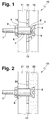
- FIG. 1 schematically shows an embodiment of the invention Plate Association 10 shown, the composite element from a building-side plate 11 and one plate 12 facing away from the building.
- the visible side of the side facing away from the building is marked with an arrow.
- the plates 11, 12, which are glass plates and / or natural or artificial stone slabs can act, are firmly connected to one another by means of a composite layer 13.
- the composite layer 13 can be, for example, a highly tear-resistant one Plastic adhesive film made of PVB, EVA or other suitable material. But you can also one or multi-component cast resin layer, an organic or an inorganic adhesive.
- the glass plates in a plate assembly according to the invention can be made from float glass, toughened glass (ESG, clear or coated), partially tempered glass (TVG, clear or coated) or multilayer bulletproof glass.
- a through hole is in the building-side plate 11 1 provided that in the face plate 12 in a Bore 2 with a conical undercut 3 merges.
- a sleeve 6 is form-fitting introduced, which is part of an undercut anchor.
- an annular Spreading element 5 on the side away from the building axial end 4 of the sleeve 6 protrudes an annular Spreading element 5 in the undercut end 3 of the Bore 2 and thus anchors the undercut anchor in the plate facing away from the building 12.
- a conical bolt 7 with an external thread the non-positively with the expansion element 5, which partially also runs within the sleeve 6, is connected.
- annular liner 14 which is in a radial area around the sleeve 6 around the composite layer 13 in this Area replaced.
- Their axial thickness t corresponds to the thickness the composite layer 13.
- the outer diameter D of the annular liner 14 be dimensioned so that the longitudinal axis in one the sleeve 6 containing plane the connecting line between the radially outermost point of the undercut finish 3 the bore 2 and the radially outermost point of the intermediate layer 14 an angle ⁇ of approximately 45 ° with the plane of the liner surface includes, as indicated in Fig. 1 is.
- the outer diameter D the annular intermediate layer 14 between 30 mm and 50 mm be.
- the inner diameter d of the intermediate layer 14, is conveniently designed in a circular shape corresponds to that Outside diameter of the sleeve 6.
- FIG. 2 shows a further exemplary embodiment, in which the panel assembly 20 according to the invention from a building side Glass plate 21, a natural stone plate on the visible side 22 and a composite layer 23 with an inserted intermediate layer 24 is constructed.
- This is advantageous Embodiment from the visible side of the fastener not recognizable with the undercut dowel 5, 6, 7, what the aesthetic impression when used as a facade element can significantly improve.
- Those parts of the sleeve 6, which should come into contact with the glass plate 21 consist of plastic or coated with plastic his.
- Fig. 3 shows an embodiment in which the panel association 30 a relatively thin natural stone slab on the building side Contains 31, the thickness of which can be, for example, 10 mm.
- a considerably thicker glass plate then serves as the carrier material 32 on the side facing away from the building, which has a Composite layer 33 and an intermediate layer 34 with the stone slab 31 is connected. In turn serves as a fastening element an undercut dowel 5, 6, 7.
- first and second plates 11, 12; 21, 22; 31, 32 can connect further panels facing away from the building, which are connected to one another by means of appropriate composite layers.
- the fastener with the undercut dowel can in this case either to the outermost visible side Plate are carried out, in which, however, it is then only partially protrudes or it can, as in FIGS to 3, only in the two closest to the building Intervene plates.
- the composite layer is always in the area between two plates according to the invention by a corresponding intermediate layer in a radial area around the sleeve 6 of the undercut anchor replaced around.
- FIG. 4a finally shows a top view of an annular Embodiment of the invention Intermediate layer 44.
- the coating 45 can be, for example Plastic coating or a passivation layer, e.g. be a metal oxide layer.
- the intermediate layer 44 can also be coated on both sides or all around. Usually will you put the liner on a glass plate with a Provide coating, while a coating on contact surfaces with stone slabs not absolutely necessary is.
- the intermediate layer 44 is advantageously made of non-corrosive, especially constructed of rustproof material to be used outdoors, e.g. on exterior facades to enable permanently.
- the intermediate layer 44 is a metal disc, preferably one Be steel disc.
- the liner between Glass plates can also be tinted or complete transparent plastic or glass pane as an intermediate layer be used.
- the slab bandage instead of on one Building surface to be fastened to interior fittings, for example as a table top or as the visible surface of a Built-in furniture or a room divider.
Landscapes
- Engineering & Computer Science (AREA)
- Architecture (AREA)
- Civil Engineering (AREA)
- Structural Engineering (AREA)
- General Engineering & Computer Science (AREA)
- Ceramic Engineering (AREA)
- Mechanical Engineering (AREA)
- Load-Bearing And Curtain Walls (AREA)
- Laminated Bodies (AREA)
- Finishing Walls (AREA)
Abstract
Description
- Fig. 1
- eine schematische, teilgeschnittene Ansicht einer Ausführungsform des Plattenverbands mit Befestigungselement und zwei Platten in einer die Längsachse der Hülse des Hinterschnittdübels enthaltenden Ebene;
- Fig. 2
- eine Ausführungsform mit gebäudeseitiger Glasplatte und sichtseitiger Steinplatte im Plattenverband;
- Fig. 3
- eine Ausführungsform mit gebäudeseitiger Steinplatte und sichtseitiger Glasplatte im Plattenverband;
- Fig. 4a
- eine Ausführungsform der Zwischenlage in Draufsicht;
- Fig. 4b
- die Zwischenlage nach Fig. 4a im Schnitt durch die Ebene A-A.
Claims (13)
- Plattenverband zur Befestigung an äußeren oder inneren Gebäudeoberflächen, beispielsweise an Hausfassaden oder an Innenwänden, oder an Innenausbau-Elementen wie z.B. Einbaumöbeln, Tischen etc., mit mindestens zwei mittels einer Verbundschicht (13; 23; 33), insbesondere einer vorzugsweise transparenten Gießharzschicht oder einer hochreißfesten Kunststoffklebefolie, fest miteinander verbundenen Platten (11, 12; 21, 22; 31, 32) aus Kunst- bzw. Naturstein und/oder Glas sowie mit einem Befestigungselement, das einerseits teilweise in den Plattenverband (10; 20; 30) ragt, und in diesem verankert ist, andererseits einen vom Plattenverband wegragenden, vorzugsweise mit einem Außengewinde versehenen Bolzen (7) zur Befestigung an einer Unterkonstruktion ggf. über ein Halterungselement aufweist,
dadurch gekennzeichnet,
daß das Befestigungselement einen Hinterschnittdübel mit einem Spreizelement (5), einer Hülse (6) und dem vom Plattenverband zur Gebäudeoberfläche wegragenden Bolzen (7) umfaßt, wobei die Hülse (6) vollständig die gebäudeseitige Platte (11; 21; 31) des Plattenverbandes (10; 20; 30) und teilweise mindestens eine gebäudeabgewandt daran anschließende Platte (12; 22; 32) bis zum axialen Ende (4) der Hülse (6) formschlüssig durchdringt, wobei im Anschluß an dieses axiale Ende (4) der Hülse (6) in der teilweise von der Hülse (6) durchdrungenen Platte (12; 22; 32) ein hinterschnittenes Bohrloch (2, 3) vorgesehen ist, in welchem das Spreizelement (5) kraftschlüssig verankert ist, und wobei die Verbundschichten (13; 23; 33) zwischen sämtlichen von der Hülse (6) vollständig oder teilweise durchdrungenen Platten (11, 12; 21, 22; 31, 32) in einem radialen Bereich um die Hülse (6) herum durch eine ringförmige Zwischenlage (14; 24; 34; 44) ersetzt sind, deren axiale Dicke t der Dicke der jeweiligen Verbundschicht (13; 23; 33) entspricht. - Plattenverband nach Anspruch 1, dadurch gekennzeichnet, daß die Zwischenlage (14; 24; 34; 44) kreisringförmig ist.
- Plattenverband nach Anspruch 1 oder 2, dadurch gekennzeichnet, daß der Innendurchmesser d der ringförmigen Zwischenlage (14; 24; 34; 44) dem Außendurchmesser der Hülse (6) entspricht.
- Plattenverband nach einem der vorhergehenden Ansprüche, dadurch gekennzeichnet, daß der Außendurchmesser D der ringförmigen Zwischenlage (14; 24; 34; 44) so bemessen ist, daß in einer die Längsachse der Hülse (6) enthaltenden Ebene die Verbindungslinie zwischen dem radial äußersten Punkt des hinterschnittenen Bohrlochs (2, 3) und dem radial äußersten Punkt der Zwischenlage (14; 24; 34) mit der Ebene der Zwischenlagenoberfläche einen Winkel α von ungefähr 45° einschließt.
- Plattenverband nach Anspruch 4, dadurch gekennzeichnet, daß der Außendurchmesser D der ringförmigen Zwischenlage (14; 24; 34; 44) zwischen 30 mm und 50 mm beträgt.
- Plattenverband nach einem der vorhergehenden Ansprüche, dadurch gekennzeichnet, daß die Zwischenlage (14; 24; 34; 44) aus nicht-korrodierendem, insbesondere aus nicht-rostendem Material aufgebaut ist.
- Plattenverband nach Anspruch 6, dadurch gekennzeichnet, daß die Zwischenlage (14; 24; 34; 44) eine Metallscheibe, vorzugsweise eine Stahlscheibe umfaßt.
- Plattenverband nach Anspruch 7, dadurch gekennzeichnet, daß die Metallscheibe zumindest einseitig, vorzugsweise an einer Berührungsfläche zu einer Glasplatte (11, 12; 21; 32), beschichtet ist.
- Plattenverband nach Anspruch 8, dadurch gekennzeichnet, daß die Metallscheibe eine Kunststoffbeschichtung aufweist.
- Plattenverband nach Anspruch 8, dadurch gekennzeichnet, daß die Metallscheibe eine Passivierungsschicht, z.B. eine Metalloxidschicht, aufweist.
- Plattenverband nach Anspruch 6, dadurch gekennzeichnet, daß die Zwischenlage (14; 24; 34; 44) eine Kunststoffscheibe umfaßt.
- Plattenverband nach Anspruch 11, dadurch gekennzeichnet, daß die Kunststoffscheibe transparent ist.
- Plattenverband nach Anspruch 6, dadurch gekennzeichnet, daß die Zwischenlage (14; 24; 34; 44) eine Glasscheibe umfaßt.
Applications Claiming Priority (2)
| Application Number | Priority Date | Filing Date | Title |
|---|---|---|---|
| DE19751124A DE19751124C1 (de) | 1997-11-19 | 1997-11-19 | Stein- und/oder Glas-Verbundelement mit Hinterschnittdübel |
| DE19751124 | 1997-11-19 |
Publications (3)
| Publication Number | Publication Date |
|---|---|
| EP0918119A2 true EP0918119A2 (de) | 1999-05-26 |
| EP0918119A3 EP0918119A3 (de) | 1999-09-01 |
| EP0918119B1 EP0918119B1 (de) | 2003-03-12 |
Family
ID=7849115
Family Applications (1)
| Application Number | Title | Priority Date | Filing Date |
|---|---|---|---|
| EP98118909A Expired - Lifetime EP0918119B1 (de) | 1997-11-19 | 1998-10-07 | Stein- und/oder Glas-Verbundelement mit Hinterschnittdübel |
Country Status (3)
| Country | Link |
|---|---|
| EP (1) | EP0918119B1 (de) |
| AT (1) | ATE234402T1 (de) |
| DE (1) | DE19751124C1 (de) |
Cited By (3)
| Publication number | Priority date | Publication date | Assignee | Title |
|---|---|---|---|---|
| WO2005017297A1 (fr) * | 2003-08-08 | 2005-02-24 | Saint-Gobain Glass France | Element feuillete en forme de plaque avec une fixation de position pour un assemblage colle |
| WO2008141531A1 (fr) * | 2007-05-22 | 2008-11-27 | Kohler (China) Investment Company Ltd. | Structure à panneau de pierre |
| CN106891605A (zh) * | 2017-01-24 | 2017-06-27 | 翔实节能玻璃(昆山)有限公司 | 夹层钢化玻璃安装孔定位结构及其加工方法 |
Families Citing this family (6)
| Publication number | Priority date | Publication date | Assignee | Title |
|---|---|---|---|---|
| DE29913278U1 (de) * | 1999-07-29 | 2000-12-07 | fischerwerke Artur Fischer GmbH & Co. KG, 72178 Waldachtal | Befestigungselement für Doppelglasplatten |
| DE20007514U1 (de) * | 2000-04-26 | 2001-09-06 | fischerwerke Artur Fischer GmbH & Co. KG, 72178 Waldachtal | Befestigungselement |
| DE10054816B4 (de) | 2000-07-06 | 2005-09-22 | Saint-Gobain Glass Deutschland Gmbh | Befestigungsanordnung für ein Wandelement in Verbundbauweise und Wandelement |
| DE102005011741B4 (de) * | 2005-03-11 | 2007-01-18 | Munch, Paul-Jean, Dipl.-Ing. | Befestigung für einen Beschlag an einem plattenförmigen Element |
| US10562274B1 (en) * | 2016-02-22 | 2020-02-18 | Apple Inc. | Glass fastening and sealing systems |
| GB2575105A (en) | 2018-06-29 | 2020-01-01 | Airbus Operations Ltd | A duct stringer |
Citations (1)
| Publication number | Priority date | Publication date | Assignee | Title |
|---|---|---|---|---|
| EP0799949A1 (de) | 1996-04-04 | 1997-10-08 | J. Prof. Dr. Blanke-Bohne | Natursteinelement |
Family Cites Families (6)
| Publication number | Priority date | Publication date | Assignee | Title |
|---|---|---|---|---|
| DE3110101A1 (de) * | 1981-03-16 | 1982-09-23 | Albert 7251 Hemmingen Fink | "vorrichtung zum befestigen einer fassadenplatte an einer traegerunterkonstruktion" |
| EP0367908A1 (de) * | 1988-10-28 | 1990-05-16 | Josef Gartner & Co. | Rahmenlose Verglasung |
| DE4002512A1 (de) * | 1990-01-29 | 1991-08-01 | Fischer Artur Werke Gmbh | Befestigung fuer fassadenplatten |
| DE4204822C2 (de) * | 1991-09-06 | 2000-10-19 | Hp Betonfertigteile Und Beratu | Fassadenplatte |
| DE4233695C2 (de) * | 1992-10-07 | 1996-07-11 | Wicona Bausysteme Gmbh | Verbundplatte für Wandbekleidungen |
| DE9306937U1 (de) * | 1993-02-17 | 1993-08-19 | Eischeid, Karl, 51766 Engelskirchen | Befestigungseinrichtung für ein nicht durchgehendes hinterschnittenes Bohrloch |
-
1997
- 1997-11-19 DE DE19751124A patent/DE19751124C1/de not_active Expired - Fee Related
-
1998
- 1998-10-07 EP EP98118909A patent/EP0918119B1/de not_active Expired - Lifetime
- 1998-10-07 AT AT98118909T patent/ATE234402T1/de not_active IP Right Cessation
Patent Citations (1)
| Publication number | Priority date | Publication date | Assignee | Title |
|---|---|---|---|---|
| EP0799949A1 (de) | 1996-04-04 | 1997-10-08 | J. Prof. Dr. Blanke-Bohne | Natursteinelement |
Cited By (6)
| Publication number | Priority date | Publication date | Assignee | Title |
|---|---|---|---|---|
| WO2005017297A1 (fr) * | 2003-08-08 | 2005-02-24 | Saint-Gobain Glass France | Element feuillete en forme de plaque avec une fixation de position pour un assemblage colle |
| CN1833088B (zh) * | 2003-08-08 | 2010-09-08 | 法国圣戈班玻璃厂 | 用于粘合连接的具有位置固定装置的叠层板状件 |
| US8656676B2 (en) | 2003-08-08 | 2014-02-25 | Saint-Gobain Glass France | Plate-shaped laminated element with position fixing element for a bonded assembly |
| WO2008141531A1 (fr) * | 2007-05-22 | 2008-11-27 | Kohler (China) Investment Company Ltd. | Structure à panneau de pierre |
| CN106891605A (zh) * | 2017-01-24 | 2017-06-27 | 翔实节能玻璃(昆山)有限公司 | 夹层钢化玻璃安装孔定位结构及其加工方法 |
| CN106891605B (zh) * | 2017-01-24 | 2019-03-19 | 翔实节能玻璃(昆山)有限公司 | 夹层钢化玻璃安装孔定位结构及其加工方法 |
Also Published As
| Publication number | Publication date |
|---|---|
| DE19751124C1 (de) | 1999-04-15 |
| EP0918119B1 (de) | 2003-03-12 |
| EP0918119A3 (de) | 1999-09-01 |
| ATE234402T1 (de) | 2003-03-15 |
Similar Documents
| Publication | Publication Date | Title |
|---|---|---|
| EP0654111B1 (de) | Konstruktions-bauelement für die verglasung von bauten | |
| DE19947913C2 (de) | Befestigungselement zur Anbringung von Lasten an eine eine Wärmedämmung aufweisende Gebäudewand | |
| EP0918119B1 (de) | Stein- und/oder Glas-Verbundelement mit Hinterschnittdübel | |
| EP0328030B1 (de) | Natursteinelement für die Verkleidung von Bauwerkfassaden | |
| DE102008058389A1 (de) | Punktbefestiger, Klebeverbindung und Verfahren zum Herstellen einer Klebeverbindung | |
| DE4130823C2 (de) | Glasscheibe mit Befestigungselement | |
| DE29720458U1 (de) | Stein- und/oder Glas-Verbundelement mit Hinterschnittdübel | |
| DE102007037271A1 (de) | Vorrichtung zum Befestigen von plattenartigen Verkleidungselementen | |
| DE4233695A1 (de) | Verbundplatte für Wandbekleidungen | |
| DE10153844B4 (de) | Vorrichtung zur lösbaren Befestigung von wenigstens einem Flächenelement, ein System mit mehreren solcher Vorrichtungen und deren Verwendung | |
| EP1482188A2 (de) | Befestigungsvorrichtung mit thermischer Trennung | |
| EP2455562A1 (de) | Schraube zum Befestigen eines Wärmedämmpaneels und Wärmedämmpaneelverkleidung | |
| DE69521260T2 (de) | Befestigung von Glasscheiben | |
| EP2340373B1 (de) | Schraube und damit hergestellte verbindung | |
| DE9400659U1 (de) | Bauelement mit einer Betonplatte und wenigstens einer daran befestigten Steinplatte | |
| DE10037683C2 (de) | Befestigungsvorrichtung für flächenartige Elemente | |
| DE19836336C2 (de) | Versteifendes Bauteil | |
| EP2795008A2 (de) | Verbindung von mindestens einem bauteil aus stahl mit einem unterbau aus sprödem material | |
| DE9202055U1 (de) | Fassadenplatte | |
| EP0866195A2 (de) | Vorrichtung zur Verankerung einer Fassadenverkleidung über einer Dämmung an einer Wand | |
| EP0892178B1 (de) | Verschlusseinrichtung | |
| DE4114458C1 (en) | Thin plate fastener with head member - which has plate abutting, flat, deposition surface and elongated arrester with dovetail shape | |
| DE19924745C1 (de) | Vorrichtung zur Eckbefestigung einer Leibungsplatte | |
| DE10009994A1 (de) | Anordnung und Verfahren zum Befestigen von Gegenständen | |
| EP1162339B1 (de) | Befestigungselement für Glasscheiben |
Legal Events
| Date | Code | Title | Description |
|---|---|---|---|
| PUAI | Public reference made under article 153(3) epc to a published international application that has entered the european phase |
Free format text: ORIGINAL CODE: 0009012 |
|
| AK | Designated contracting states |
Kind code of ref document: A2 Designated state(s): AT BE CH DK ES FR GB GR IT LI LU NL PT SE |
|
| AX | Request for extension of the european patent |
Free format text: AL;LT;LV;MK;RO;SI |
|
| PUAL | Search report despatched |
Free format text: ORIGINAL CODE: 0009013 |
|
| AK | Designated contracting states |
Kind code of ref document: A3 Designated state(s): AT BE CH CY DE DK ES FI FR GB GR IE IT LI LU MC NL PT SE |
|
| AX | Request for extension of the european patent |
Free format text: AL;LT;LV;MK;RO;SI |
|
| 17P | Request for examination filed |
Effective date: 19990907 |
|
| AKX | Designation fees paid |
Free format text: AT BE CH DK ES FR GB GR IT LI LU NL PT SE |
|
| REG | Reference to a national code |
Ref country code: DE Ref legal event code: 8566 |
|
| GRAG | Despatch of communication of intention to grant |
Free format text: ORIGINAL CODE: EPIDOS AGRA |
|
| 17Q | First examination report despatched |
Effective date: 20020522 |
|
| GRAG | Despatch of communication of intention to grant |
Free format text: ORIGINAL CODE: EPIDOS AGRA |
|
| GRAH | Despatch of communication of intention to grant a patent |
Free format text: ORIGINAL CODE: EPIDOS IGRA |
|
| GRAH | Despatch of communication of intention to grant a patent |
Free format text: ORIGINAL CODE: EPIDOS IGRA |
|
| GRAA | (expected) grant |
Free format text: ORIGINAL CODE: 0009210 |
|
| AK | Designated contracting states |
Designated state(s): AT BE CH DK ES FR GB GR IT LI LU NL PT SE |
|
| PG25 | Lapsed in a contracting state [announced via postgrant information from national office to epo] |
Ref country code: NL Free format text: LAPSE BECAUSE OF FAILURE TO SUBMIT A TRANSLATION OF THE DESCRIPTION OR TO PAY THE FEE WITHIN THE PRESCRIBED TIME-LIMIT Effective date: 20030312 Ref country code: IT Free format text: LAPSE BECAUSE OF FAILURE TO SUBMIT A TRANSLATION OF THE DESCRIPTION OR TO PAY THE FEE WITHIN THE PRESCRIBED TIME-LIMIT;WARNING: LAPSES OF ITALIAN PATENTS WITH EFFECTIVE DATE BEFORE 2007 MAY HAVE OCCURRED AT ANY TIME BEFORE 2007. THE CORRECT EFFECTIVE DATE MAY BE DIFFERENT FROM THE ONE RECORDED. Effective date: 20030312 Ref country code: GR Free format text: LAPSE BECAUSE OF FAILURE TO SUBMIT A TRANSLATION OF THE DESCRIPTION OR TO PAY THE FEE WITHIN THE PRESCRIBED TIME-LIMIT Effective date: 20030312 Ref country code: GB Free format text: LAPSE BECAUSE OF FAILURE TO SUBMIT A TRANSLATION OF THE DESCRIPTION OR TO PAY THE FEE WITHIN THE PRESCRIBED TIME-LIMIT Effective date: 20030312 Ref country code: FR Free format text: LAPSE BECAUSE OF FAILURE TO SUBMIT A TRANSLATION OF THE DESCRIPTION OR TO PAY THE FEE WITHIN THE PRESCRIBED TIME-LIMIT Effective date: 20030312 |
|
| REG | Reference to a national code |
Ref country code: GB Ref legal event code: FG4D Free format text: NOT ENGLISH |
|
| REG | Reference to a national code |
Ref country code: CH Ref legal event code: EP |
|
| PG25 | Lapsed in a contracting state [announced via postgrant information from national office to epo] |
Ref country code: SE Free format text: LAPSE BECAUSE OF FAILURE TO SUBMIT A TRANSLATION OF THE DESCRIPTION OR TO PAY THE FEE WITHIN THE PRESCRIBED TIME-LIMIT Effective date: 20030612 Ref country code: PT Free format text: LAPSE BECAUSE OF FAILURE TO SUBMIT A TRANSLATION OF THE DESCRIPTION OR TO PAY THE FEE WITHIN THE PRESCRIBED TIME-LIMIT Effective date: 20030612 Ref country code: DK Free format text: LAPSE BECAUSE OF FAILURE TO SUBMIT A TRANSLATION OF THE DESCRIPTION OR TO PAY THE FEE WITHIN THE PRESCRIBED TIME-LIMIT Effective date: 20030612 |
|
| REG | Reference to a national code |
Ref country code: CH Ref legal event code: NV Representative=s name: RECHTSANWAELTE DR. IUR. MARKUS H. WANGER |
|
| NLV1 | Nl: lapsed or annulled due to failure to fulfill the requirements of art. 29p and 29m of the patents act | ||
| GBV | Gb: ep patent (uk) treated as always having been void in accordance with gb section 77(7)/1977 [no translation filed] |
Effective date: 20030312 |
|
| PG25 | Lapsed in a contracting state [announced via postgrant information from national office to epo] |
Ref country code: ES Free format text: LAPSE BECAUSE OF FAILURE TO SUBMIT A TRANSLATION OF THE DESCRIPTION OR TO PAY THE FEE WITHIN THE PRESCRIBED TIME-LIMIT Effective date: 20030930 |
|
| PGFP | Annual fee paid to national office [announced via postgrant information from national office to epo] |
Ref country code: CH Payment date: 20031027 Year of fee payment: 6 |
|
| PGFP | Annual fee paid to national office [announced via postgrant information from national office to epo] |
Ref country code: LU Payment date: 20031028 Year of fee payment: 6 |
|
| PGFP | Annual fee paid to national office [announced via postgrant information from national office to epo] |
Ref country code: AT Payment date: 20031030 Year of fee payment: 6 |
|
| PG25 | Lapsed in a contracting state [announced via postgrant information from national office to epo] |
Ref country code: BE Free format text: LAPSE BECAUSE OF NON-PAYMENT OF DUE FEES Effective date: 20031031 |
|
| PLBE | No opposition filed within time limit |
Free format text: ORIGINAL CODE: 0009261 |
|
| STAA | Information on the status of an ep patent application or granted ep patent |
Free format text: STATUS: NO OPPOSITION FILED WITHIN TIME LIMIT |
|
| EN | Fr: translation not filed | ||
| 26N | No opposition filed |
Effective date: 20031215 |
|
| BERE | Be: lapsed |
Owner name: *WENDKER & SELDERS G.M.B.H. & CO. NATURSTEIN-GLAS- Effective date: 20031031 |
|
| PG25 | Lapsed in a contracting state [announced via postgrant information from national office to epo] |
Ref country code: LU Free format text: LAPSE BECAUSE OF NON-PAYMENT OF DUE FEES Effective date: 20041007 Ref country code: AT Free format text: LAPSE BECAUSE OF NON-PAYMENT OF DUE FEES Effective date: 20041007 |
|
| PG25 | Lapsed in a contracting state [announced via postgrant information from national office to epo] |
Ref country code: LI Free format text: LAPSE BECAUSE OF NON-PAYMENT OF DUE FEES Effective date: 20041031 Ref country code: CH Free format text: LAPSE BECAUSE OF NON-PAYMENT OF DUE FEES Effective date: 20041031 |
|
| REG | Reference to a national code |
Ref country code: CH Ref legal event code: PL |