EP0918302B1 - Détecteur de cohérence - Google Patents
Détecteur de cohérence Download PDFInfo
- Publication number
- EP0918302B1 EP0918302B1 EP98122061A EP98122061A EP0918302B1 EP 0918302 B1 EP0918302 B1 EP 0918302B1 EP 98122061 A EP98122061 A EP 98122061A EP 98122061 A EP98122061 A EP 98122061A EP 0918302 B1 EP0918302 B1 EP 0918302B1
- Authority
- EP
- European Patent Office
- Prior art keywords
- disparity
- image
- image data
- supplied
- values
- Prior art date
- Legal status (The legal status is an assumption and is not a legal conclusion. Google has not performed a legal analysis and makes no representation as to the accuracy of the status listed.)
- Expired - Lifetime
Links
Images



Classifications
-
- G—PHYSICS
- G06—COMPUTING OR CALCULATING; COUNTING
- G06T—IMAGE DATA PROCESSING OR GENERATION, IN GENERAL
- G06T7/00—Image analysis
- G06T7/50—Depth or shape recovery
- G06T7/55—Depth or shape recovery from multiple images
- G06T7/593—Depth or shape recovery from multiple images from stereo images
-
- G—PHYSICS
- G06—COMPUTING OR CALCULATING; COUNTING
- G06T—IMAGE DATA PROCESSING OR GENERATION, IN GENERAL
- G06T2200/00—Indexing scheme for image data processing or generation, in general
- G06T2200/28—Indexing scheme for image data processing or generation, in general involving image processing hardware
-
- G—PHYSICS
- G06—COMPUTING OR CALCULATING; COUNTING
- G06T—IMAGE DATA PROCESSING OR GENERATION, IN GENERAL
- G06T2207/00—Indexing scheme for image analysis or image enhancement
- G06T2207/10—Image acquisition modality
- G06T2207/10004—Still image; Photographic image
- G06T2207/10012—Stereo images
-
- H—ELECTRICITY
- H04—ELECTRIC COMMUNICATION TECHNIQUE
- H04N—PICTORIAL COMMUNICATION, e.g. TELEVISION
- H04N13/00—Stereoscopic video systems; Multi-view video systems; Details thereof
- H04N13/20—Image signal generators
- H04N13/204—Image signal generators using stereoscopic image cameras
- H04N13/239—Image signal generators using stereoscopic image cameras using two two-dimensional [2D] image sensors having a relative position equal to or related to the interocular distance
-
- H—ELECTRICITY
- H04—ELECTRIC COMMUNICATION TECHNIQUE
- H04N—PICTORIAL COMMUNICATION, e.g. TELEVISION
- H04N13/00—Stereoscopic video systems; Multi-view video systems; Details thereof
- H04N2013/0074—Stereoscopic image analysis
- H04N2013/0081—Depth or disparity estimation from stereoscopic image signals
Definitions
- the present invention relates to a coherence detector for use in an image processing device, especially in a stereoscopic device Image processing.
- the optical detection of the three-dimensional environment wins has become increasingly important for some time.
- the robots used must have two-dimensional coordinates also depth information regarding a (to be processed) Object are available, for example to be able to control a robot accordingly.
- Previously known implementations for determining depth information can be divided into different groups, which are based on different procedures.
- Triangulation methods use one or more lines, either from a laser or a projection unit are mapped to the object in question. With a or several cameras, the object is then under a slightly different from the projection direction, another point of view. Based on the known Geometric relationships then take place using trigonometric calculations to determine the three-dimensional Structure of the object.
- the respective The object to be illuminated is to be illuminated. This does under Laboratory conditions are not a problem, but will be in practice almost impossible when in situations such as traffic or under difficult existing with telescopes or microscopes real-world measurements. Furthermore, lasers used as line light projectors to observe special accident prevention regulations, so with such test setups no danger for human eye exists.
- runtime methods evaluate the runtime of light, Microwaves or a sound signal as a measurement signal out to draw conclusions about the spatial environment and the To draw depth information.
- a spatial direction targeted and made a distance measurement.
- Runtime procedures require a complex Signal processing and are also of the properties of the surrounding medium depending on the propagation properties of the measurement signal concerned.
- Depth of field methods are also used, the however can only be applied if the object size and opening a lens in a particular one Are related to each other, such as in microscopy. In doing so, only the narrow area of the focal plane sharp on an image sensor displayed. The areas in front and behind are more or less unfocused.
- the one contained in the focal plane Image information can be processed using conventional image processing techniques be evaluated. A corresponding evaluation then returns a contour of the object. By multiple Moving the focal plane and subsequent evaluation then a contour map of the object can be created, however, which is correspondingly complex.
- the phenomenon of spatial vision which is briefly described below in Relation to humans is generally based on the perception of the visible environment by means of the two human eyes, the due to the eye relief two perceived images (right eye or image, left Eye or image) from slightly different angles be perceived. Because the visual axes of the eyes are something converge, their visual axes meet at one Point of the environment under consideration, being from a fixation this point is spoken through the eyes. The picture this point falls on a visual pit of the retina. Each neighboring point in the visual field will then open up a location of the retina that projects somewhat from the center from the sharpest vision. Generally is this distance is different in both eyes, with the Distance as a function of the spatial depth of the considered Point in the visual field varies relative to the fixation point. These distance deviations are called binocular disparities referred to below as "disparities" are designated.
- the real problem with stereo viewing is besides that Evaluation of the given trigonometric conditions in figuring out which pixel the real one World or of the object seen in the first of the stereoscopic Images occurs, which pixel in the second corresponds to the stereoscopic images.
- disparities For spatial vision or 3D stereo perception it then becomes necessary from the disparities to the three-dimensional Close the structure of the perceived image.
- from identified disparities can refer to the depth information contained in the perceived image getting closed.
- Stereo processes endeavor to match corresponding pixels between a first (left) and a second (right) Find stereo image, then from the relative shift such pixels with a known camera position the distance of the points can be calculated.
- stereo methods distinguish between so-called feature-based Stereo method, intensity based stereo method and phase-based stereo process.
- the correspondence search is carried out certain characteristics (e.g. edges or intensity maxima) extracted from the image data for more stable than the raw image intensities are kept.
- characteristics e.g. edges or intensity maxima
- Such Procedures are stable if there are few stable features (such as object edges) are extracted. You are too fast because images are only processed at the locations on which characteristics were recorded. this leads to a noticeable data reduction.
- Intensity-based stereo processes work directly with the supplied by the stereo cameras or image recorders Image brightness. Therefore, they are related to each other to use very stable algorithms of appropriate brightness, which require a corresponding amount of computing time. Under The intensity-based process can be further differentiated are between correlation based methods and Dynamic programming method.
- the former strive to have a small image area of the left Picture in the right picture. This is usually done Procedure to maximize correlation or Minimizing the difference used. If the image sections large enough, you can achieve them Process stable and dense disparity cards, one Real time processing using special complex Hardware is conceivable.
- the raw disparity cards included typically, however, only shifts in the area of accuracy of a picture element (pixel) so that the resolution is limited. Only by using interpolation methods or else iterative methods can increase the accuracy of the Disparities improved to sub-pixel accurate disparities become.
- Such correlation-based methods are, for example in the publication DE 34 25 946 A1 and the article "A stereovision system for a planetary rover: calibration, correlation, registration, and fusion "by Z. Zhang, in: Machine Vision and Applications, No. 10, 1997, pp.27-34.
- intensity-based Procedure a dense disparity map (a disparity value for almost every pixel), the minimization the measure of error as in the method of minimizing the Difference, however, is time consuming and therefore not for Real-time applications is suitable. Reducing the required Computing time can be increased by using hierarchical Procedures can be reduced, but only through use complicated and not parallelizable algorithmic Structures for which a hardware solution is at least extreme becomes complex and therefore costly.
- Phase-based stereo processes are also an issue current investigations. These procedures extract from a local Fourier phase (usually through Filtering using Gabor functions), and then try either, these Fourier phase images (for the right or left picture) (e.g. described by Weng) in agreement or by using Fourier's shift theorem to calculate the local shift (e.g. described by Sanger, Fleet & Jepson).
- the extraction effectively corresponds to the local Fourier phase a local contrast compensation, which makes many through Variations in brightness caused errors in other stereo processes be reduced.
- These phase-based stereo processes work with sub-pixel accuracy and are also for real-time applications implementable. However, for generation hierarchical procedures are used are usually special for avoiding errors Catch exceptional situations (see Fleet). This makes the algorithms used complicated and one Hardware implementation complex and costly.
- this object is achieved as defined in claim 1,
- the object is further achieved by an image processing device with shifting devices for mutual Shift of these respectively supplied image data a first picture and one to this under another Angle taken second image, the Image data in parallel on the shifting devices be tapped and in pairs a subsequent disparity detection device be fed; being the Disparity detection device for each of the supplied Image data pairs using a respective disparity element a spatial depth information for each Determining the disparity value representing the image data pair, and the determined disparity values of a coherence detection device feeds, where the output disparity value determined for each shift of the image data and the associated spatial depth information represents.
- the feeds Image signals are processed at the speed as they are supplied by image recorders. So that is Image data processing for obtaining depth information possible with little effort and in real time.
- This high processing speed (real time) of the system is a significant advantage over the state of the Technology.
- a frame rate of, for example, 25 frames per second fed to the system by the image sensor and are processed by it in real time is the system or the method implemented with it the arrangements known from the prior art or Procedure at least by a speed factor of 100 think.
- the volume of the object to be measured is opposite known systems no longer limited.
- the measuring range of the image processing device according to the invention only by limiting the imaging used Optics determined, and all optical attachments such as microscopes, telephoto or wide-angle lenses can in Connection with the image sensors can be used, provided they are adapted to them.
- the device according to the invention also does not apply pretreatment of the test object itself, for example covering the test object with light powder for removal of reflections and highlights on the object surface before measuring and removing the powder after Measurement. By saving such operations the device according to the invention works in time and cost-effective.
- the device according to the invention is not limited to the area of visible light, but for example, the evaluation can also be carried out for image signals Infrared range.
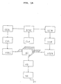
- FIG. 1A shows the stereoscopic image processing device according to the invention for capturing three-dimensional Diagram objects in real time as a block diagram.
- the image processing device has a sensor head which comprises two image recorders, one image pickup CCDL for the (first) left image and an image sensor CCDR for the (second) right picture.
- One of these pictures will thereby for the subsequent processing as a reference image Are defined. That is, determined disparity results to create a disparity map the image data of the reference image be assigned.
- the image recorders can be, for example Acting camera pair with CCD imagers in one predetermined known distance d from each other are and therefore slightly different images of the same Take object (see. Fig. 1B and Fig. 6).
- the image recorders can record moving images and these feed the device for subsequent real time processing.
- SYNC will be the recordings of the image pickup devices CCDL, CCDR synchronized in time, so that left and right picture taken synchronously to each other become.
- a disparity detector DD Device and one as a disparity coherence detector KD designated facility (both below are described in detail) may be actual Disparities or shifts are determined and then through trigonometric calculations taking into account the known distance d between the image recorders CCDL, CCDR calculates the spatial distance of the respective object are thus obtained the depth information sought become.
- the depth information calculated in this way from two stereo moving images can be practically instantaneous in real time as a video signal output and as a third dimension (e.g. third image) is shown as a grayscale image or color image become.
- the real-time processing of the system is particularly important through the serial processing the through the Image sensor CCDL, CCDR conditionally delivered image data.
- a clock generator CLK Connected to the image sensor synchronization device SYNC is a clock generator CLK, the clock signals for Control and synchronization of other system components generated.
- the recorded image signals are used by the image recorders CCDL, CCDR assigned to these preprocessing devices VVL, VVR supplied.
- VVL preprocessing facilities
- VVR there is a brightness compensation of the two stereo images before subsequent processing.
- This brightness preprocessing is advantageous because slightly different image recording angle of the image sensor CCDL, CCDR so-called highlights and reflections on (reflective) surfaces of the recorded objects can occur in the subsequent processing the image data to record the disparities to errors can lead, so that the disparity values become unstable could.
- color images can be in the frame the preprocessing by the preprocessing facilities a breakdown of the respective (first and second) Color image data in respective color image components (e.g. in the primary colors red, green, blue (RGB) or in Luminance and the two color difference components). It is also possible to use the first and second To subject image data to different preprocessing.
- first and second To subject image data can be used to different preprocessing.
- the image data are preprocessing devices VVL, VVR of the first and second (or left and right) picture respectively Devices VSEL, VSER for mutual displacement the left and right image data in relation to each other fed. More precisely, this means that two displacement devices each VSEL, VSER form a displacement unit, whereby each with a shift current of image data "Right" and "Left” per shifting unit.
- a displacement unit is for to provide any kind of image data. That is, in the case of one Preprocessing by splitting into the primary colors R, G and B three displacement units can be provided, and one for each primary color.
- the disparities of image data shifted relative to one another in this way are then for respective image data pairs by the disparity detector DD determined and a respective set received Disparity values for the image data pairs are determined by the Disparity coherence detector KD evaluated.
- This coherence detection with regard to the disparities obtained is based on the selection or determination of that of obtained disparity values, which are approximately identical to at least one other of the disparity values obtained is.
- the disparity value becomes that actual or true disparity value determined in approximately identical to at least one other disparity value (i.e. in a predetermined interval around this) or identical to at least one other disparity value is.
- Fig. 5 illustrates this principle using data from, for example seven disparity elements of a disparity detector.
- disparity coherence detector KD determines whether actual disparity values are then from this to a facility NB for post-processing image data output.
- This device NB prepares the disparity values so that this via an output connector DV one optionally connectable output device such as Example of a display device (not shown) can be and from this as a gray value or Color image can be reproduced.
- the disparity values are carried out as part of the image data postprocessing also eliminating edge effects that occur as well as a virtual limit.
- An external control unit is not shown in the figure itself to configure the system by a Workstation computer with a suitable interface to the system can be implemented.
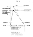
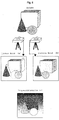
- FIG. 1B schematically shows the principle of a stereoscopic Image capture.
- CCDL CCDR they are all in one
- the distance d is the distance between the optical axes of the lenses defined as vertical running dash-dotted lines are drawn.
- the Point P2 is further in the direction of the optical axis removed as the point P1.
- the point P1 lies in one reference plane defined as the fixation plane for which a (relative) disparity of zero is assumed. Different expressed, is the determined disparity at the fixation level based.
- a suitable advance e.g. y1, or y2
- the first and second image data can thus be the fixation plane determined and the basic measuring range can be determined.
- the fixation level in an interval of disparity values [-x ..., 0, ..., + x] surrounds the so-called fusion area.
- the fusion range corresponds to a "depth of field".
- the (relative) disparity values in the fusion area are due to the shifting devices VSEL, VSER additional contingent shift of the image data determined. The greater the additional shift is evaluated, the larger the Fusion area and thus the "depth of field" around the Fixation level.
- the additionally achievable shift stands both in connection with the number n of displacement elements of the displacement devices described below, as well as the way of controlling them.
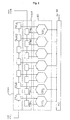
- the image data shifting device VSEL for image data of the (first) left image
- the image data shifter VSER for Image data of the (second) right image, which together form one Form shift unit
- the disparity detector DD as a disparity determining device.
- the components 2 does not refer to a specific implementation fixed in analog or digital technology and their description is initially general, independent from the actual form of realization.
- VVL, VVR output image data are the image data shifters VSEL, VSER fed. This supply takes place as mentioned above, with a pre-shift according to the desired basic measuring range. In the shown There is only one case to simplify the illustration Shift unit for one type of image data, for example shown for one of the primary colors R, G, B.
- the picture elements are shifted against each other.
- the evaluation of the picture elements with regard to the existing disparity is then carried out in pairs. More precisely, the disparity is evaluated in pairs based on the shifted image data for pairs ( ⁇ X L1 , ⁇ X Rn ), ( ⁇ X L2, ⁇ X Rn-1 ), ..., ( ⁇ X Ln-1, ⁇ X R2 ), ( ⁇ X Ln , ⁇ X R1 ).
- the amount ⁇ X of the shift can be set to a value corresponding to the length of a picture element.
- this shift can, however, also be set to a value that is smaller than the length of a picture element, for example half the length of a picture element (pixel).
- this requires a higher number of elements of the disparity detector described below if the fusion area is to remain constant.
- VSEL In the case of shifting devices implemented as an analog circuit VSEL, VSER each consist of a chain or cascade of delay elements (delay elements) with appropriate signal taps.
- the shift amount in the x-direction then corresponds to the runtime and can be picture element by picture or selected in fractions of picture elements his.
- VSER In the case of shifting devices implemented as digital circuits VSEL, VSER consists of the respective unit shift registers connected in series, to which a corresponding Clock signal from the clock generator CLK (if necessary. via an intermediate frequency divider (not shown) is to be fed. But then it is necessary the analog image data using an analog / digital converter convert into digital image data. On such analog / digital converter can be before or after respective preprocessing device VVL, VVR in the signal curve be provided depending on whether the preprocessing still analog or digital.
- the shifting elements ⁇ X Li , ⁇ X Ri of the respective shifting device for shifting by picture elements are carried out in accordance with the clock with which the digital image data are supplied.
- the already digitized data must be fed to a special filter. For example, a shift corresponding to half a picture element is achieved by averaging two successive picture elements by means of a corresponding filter and taking the value obtained as the signal value of the picture element at the position shifted by half a picture element. Such filtering then essentially corresponds to dithering of neighboring picture elements.
- the control can be used for both displacement devices VSEL, VSER take place simultaneously, or alternatively in phase opposition take place, depending on which additional shift range ("Depth of field”) is desired.
- controls are shifts by -7, -5, -3, ..., +5 as well as -6, -4-, -2, ...., +6 possible. Because of the larger additional shift is included an extended depth of field is to be expected.
- the evaluation can be gradient-based, tensor-based, energy-based or according to Reichard's diffraction detection model.
- These evaluation principles are adequately described in the specialist literature (e.g. Barron, Fleet & Jepson, Adelson & Berger DJ Fleet and AD Jepson, Stability of Phase Information, IEEE Trans. Patt. Anal. Mach. Intel. 15, 1253- 1268, 1993 JL Barron, DJ Fleet and SS Beauchemin, Performance of Optical Flow Techniques, Int. J. Comp. Vis. 12, 43-77, 1994 EH Adelson and JR Bergen, Spatiotemporal Energy Models for the Perception of Motion, J. Opt. Soc. Am. A 2, 284-299, 1985. 15) and it will not be discussed in detail here.
- the disparity values output by the disparity elements EST i (1 i i n n) are subsequently fed to the coherence detector KD, which determines the actual disparity value from the supplied values.
- the coherence detector KD determines the actual disparity value from the supplied values.
- all outputs of the respective disparity detectors are fed to a subsequent coherence detector KD.
- 3A now shows in detail a functional circuit diagram of a disparity element EST i , in which the evaluation is based on the gradient-based approach.
- Image data ⁇ X Li , ⁇ X Rn + 1-i (1 i i n n) are supplied to the respective disparity element EST i . These are then fed to a unit performing a pixel-by-pixel (pixel-by-pixel) addition (reference symbol "+”), then to a multiplication unit designated by the reference symbol "1/2", which carries out a multiplication of the added pixel values by a factor of 1/2, so that averaging takes place with respect to the pair of image data supplied in each case.
- the image data processed in this way then pass through a derivative filter DIFF.
- a simple derivative filter DIFF can have filter coefficients, for example, as are given in Table 1 below.
- the data values output by this filter are subjected, on the one hand, to pixel-by-pixel squaring in a unit denoted by the reference symbol “x 2 ”, the values obtained in this way then being fed to an averaging filter AVE.
- the data output by the filter DIFF are fed to a multiplication unit (reference symbol "*"), where they are multiplied pixel by pixel by the difference of the data ⁇ X Li , ⁇ X Rn + 1-i obtained pixel by pixel by means of a subtraction unit (reference symbol "-").
- the values obtained in this way which are available at the output of the multiplication unit, are likewise fed to a further averaging filter AVE.
- filter coefficients can be selected, such as those found in B. are shown in the following Table 2.
- the data values obtained at the outputs of both averaging filters are finally fed to a division unit (reference symbol “+”), which outputs the respectively determined disparity value at its output as the output signal of the respective disparity element EST i .
- the disparity values determined in this way which are output at the outputs of the disparity elements EST i , are then fed to the disparity coherence detector KD.
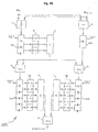
- FIG. 3B shows a block diagram for the hardware implementation of an individual disparity element EST i , which was described functionally above with reference to FIG. 3A.
- a disparity element EST consists of shift registers SR1 to SR4 clocked from the clock generator CLK and clocked for the synchronization of the entire circuit for temporary storage of individual picture elements, as well as arithmetic logic circuits (mean value generator 1: " ⁇ / 2", subtractor 2: “-”, Multiplication devices 4, 5: MUL, summers 3, 6, 7: " ⁇ ", division device 8: DIV).
- the filter designated DIFF in FIG. 3A is now implemented by the shift register SR1, a coefficient multiplication part K (K1, K2, K3) and the summer 3.
- FIG. 4A shows a block diagram for a coherence detector or disparity coherence detector KD according to a first Embodiment, a coherence detector as an example KD is shown with only four inputs.
- a coherence detector as an example KD is shown with only four inputs.
- the circuit shown in FIG. 2 would have to be corresponding expanded to seven inputs or generally to n inputs become. If several (z) displacement units with respectively assigned disparity detectors DD with n EST each Elements would be provided, the switching would be to z * n inputs to expand.
- the data values of the ascertained disparities supplied by the (not shown) EST elements EST i and applied to the inputs E1 to E4 are fed to a sorting device S1, which outputs the data values sorted at the outputs A to D according to the size of the values. In the case shown, output A has the smallest value, output D has the largest value.
- sorting devices can be implemented with logic gates consisting of comparators (comparators) and multiplexers and are not explained in detail here.
- Each of the outputs A to D is fed to a multiplexer MUX1, while two of the outputs are each fed to a subtractor ("-") in order to determine the differences BA, CB and DC of the corresponding values.
- the differences are fed to a further sorting device S2 which, in accordance with the first device S1, outputs the values of the differences sorted at the output at the output.
- a further sorting device S2 which, in accordance with the first device S1, outputs the values of the differences sorted at the output at the output.
- only the smallest result (at the " ⁇ " output) is to be processed further, which represents the pair of values of the disparities that are "most adjacent" to one another, that is to say have the smallest deviation from one another.
- This variant represents the simpler variant in terms of circuitry, because this would also be ascertainable from the internal decision states of the sorter S2.
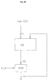
- the result obtained by the device checking for equality in turn serves to control the multiplexer MUX1 in order to supply the two output signals of the sorter S1 belonging to the difference to an averager (reference symbol " ⁇ / 2"), which adds the two values for determining the mean value and then by two divided.
- This mean value then represents the result KE, that is to say the coherence value of the large number of disparity values determined.
- a variant of the circuit described above exists therein, the differences determined with a threshold to compare, with only the candidates or values to be processed below the certain Threshold, or within a threshold certain window value range (e.g. according to the Fusion area).
- a downstream rear derailleur finds the largest cluster of neighboring candidates. Both variants are possible and can be related to the respective one Use case the better results deliver.
- FIG. 4B shows an embodiment variant of the previously described Coherence detector KD, in which the coherence detector in addition to output signals of the EST elements, further data is supplied become.
- This can be used in particular if receive the image data interlaced or "interlaced" and all the image information of one Full screen e.g. composed of two fields. Then are the disparity values for image data one Field determined and the corresponding coherence value of Disparities determined for pixels of a field. For a respective field becomes the KE values for the pixels of the field in a memory device MEM (with a storage capacity for one field), and read out during the next field period and the coherence detector KD on an additionally to be provided Input connector supplied.
- MEM memory device
- the internal structure of the coherence detector KD is essentially identical to that in Connection described with Fig. 4A, with the difference that he can process an additional (the feedback) signal must be able to do what different variants are possible are.
- the feedback coherence disparity value are already fed to the sorter S1 and be taken into account there, or later at influence the averaging. In the latter case it would be it to the averager (reference symbol " ⁇ / 2").
- the circuit shown in FIG. 4A is then corresponding in each case to modify.
- the present n disparity values by means of the coherence detector selected in each case KD according to the first or second embodiment in Processed or compared in real time, and that disparity value output as the actual disparity value, which is almost identical to as many others as possible supplied disparity values. More precisely, that means that as many disparity values as possible in an interval of z. B. about 0.2 to 0.4 around the disparity value in question should lie around so that this disparity value in question is the actual disparity value. The easiest it is when there are multiple disparity values for a particular picture element have the same value. This case corresponds in the graphic representation according to FIG. 5 an intersection of at least two of the n disparity values for a particular one Pixel.
- the line-by-line analysis of the n disparity values for each picture element of a relevant line then provides, for example, a course of the actual Disparity for a relevant line of the image as in the right part of Fig. 5 is shown, from the total a disparity map of the analyzed image lines determined or represented in the form of a third image can be (upper picture on the right in Fig. 5).
- disparity elements EST can guarantee the accuracy or reliability of the true disparity determined by the coherence detector be increased because there are more disparity values, which are evaluated for their coherence.
- each disparity element EST calculates the disparity in the entire measuring range, i.e. completely parallel. therefore the many known from the prior art are omitted Realizations necessary iterative approximation of rough ones towards fine measuring ranges, around the actual disparity value to investigate.
- FIG. 6 shows a further example of image recorders CCDL, CCDR captured images "left image” (a) and "right picture” (b) of objects arranged in space.
- Both pictures have a first and a second object in front of another (third) object, which is in the background the spatial scene shown can be seen.
- Sensor system for processing stereoscopic images in A disparity card (c) is then obtained in real time as a gray scale image (or as a color image) on a screen can be represented.
- an object in the foreground is highlighted, an object in the middle depth range a light to dark gray value corresponding to the depth shown, and the object in the background as the object with the greatest depth is approximate in the disparity map reproduced in black.
- the one in the given example 6 described form of representation for the depth information is not mandatory, however. As well objects in the foreground may appear dark, and objects in the background are bright.
- the data can display the disparity card can also be used for control purposes by this data is used, for example, to control robots during assembly processes and a target-actual comparison with predefined 3-D manufacturing data and the depth information determined from the disparities.
- Unmanned vehicles can reach and / or fall below a predetermined minimum depth value for prevention of collisions through appropriate controls to be evaded, this principle also when implementing passive and / or active distance warning and anti-collision systems can be used in motor vehicles is.
- Show other possible uses for the system in medical technology for example in three-dimensional Scanning body contours for the classification of Dysplasias.
Landscapes
- Engineering & Computer Science (AREA)
- Computer Vision & Pattern Recognition (AREA)
- Physics & Mathematics (AREA)
- General Physics & Mathematics (AREA)
- Theoretical Computer Science (AREA)
- Signal Processing (AREA)
- Multimedia (AREA)
- Image Processing (AREA)
- Length Measuring Devices By Optical Means (AREA)
- Measurement Of Mechanical Vibrations Or Ultrasonic Waves (AREA)
- Testing, Inspecting, Measuring Of Stereoscopic Televisions And Televisions (AREA)
- Image Analysis (AREA)
- Sorting Of Articles (AREA)
Claims (13)
- Détecteur de cohérence comportant
un grand nombre de n entrées de signaux (ESTi) (1<=i<=n ; E1, E2, E3, E4) auxquelles s'applique une valeur de signal d'entrée respective,
un premier dispositif de tri (S1) pour le tri des n valeurs de signaux d'entrée (E1,...,E4) amenées suivant leur valeur (A,B,C,D) et pour la sortie parallèle des n valeurs triées,
un grand nombre de n-1 dispositifs de soustraction ("-") pour la soustraction de deux valeurs triées voisines ((D-C), (C-B), (B-A)),
un deuxième dispositif de tri (S2) pour le tri des n-1 différences obtenues ((D-C), (C-B), (B-A)) suivant leur valeur et pour la sortie de la plus petite différence ("<<"),
un dispositif de sélection ("=", MUX1) qui délivre, à l'aide de la plus petite différence ("<<") déterminée, la paire de valeurs correspondante des valeurs de signaux d'entrée, et
un dispositif de sortie ("Σ/2") auquel est envoyée la paire de valeurs sortie et qui délivre sa valeur moyenne (KE). - Détecteur selon la revendication 1, dans lequel
le dispositif de sélection ("=", MUX1) contient
une unité comparative ("=") qui, par comparaison de la plus petite différence avec les n-1 valeurs différentielles, détermine la valeur différentielle qui correspond à la plus petite différence, et
une unité de multiplexage (MUX1) qui, sur la base de la commande par le résultat de la comparaison, préparé par l'unité de comparaison, délivre la paire de valeurs des valeurs de signaux d'entrée avec la plus petite différence. - Dispositif de traitement d'image comportant
des dispositifs de déplacement (VSEL, VSER; ΔXL1,..., ΔXLn, ΔXR1, ..., ΔXRn) pour le déplacement réciproque de ces données d'image, amenées dans chaque cas, d'une première image et d'une deuxième image, prise de celle-ci sous un autre angle de prise de vue, les données d'image étant prélevées parallèlement dans les dispositifs de déplacement (VSEL, VSER), et acheminées deux par deux ((ΔXL1, ΔXRn), (ΔXL2, ΔXRn-1), ..., (ΔXLn-1, ΔXR2), (ΔXLn, ΔXR1)) à un
dispositif de détection de disparité (DD ; EST1, ..., ESTn) suivant ; le dispositif de détection de disparité (DD) déterminant, pour chacune des paires de données d'image ((ΔXLI, ΔXRn+1-i)) amenées, au moyen d'un élément de disparité (EST1, ..., ESTn) respectif, une valeur de disparité qui
représente des informations spatiales de profondeur pour la paire de données d'image respective, et envoyant les valeurs de disparité déterminées à un dispositif de détection de cohérence (KD) selon l'une des revendications 1 ou 2,
la valeur de disparité (KE) délivrée étant déterminée sur chaque déplacement des données d'image et représentant l'information spatiale de profondeur correspondante. - Dispositif de traitement d'image selon la revendication 3, dans lequel
les donnés d'image d'une image complète sont acheminées, pendant deux périodes de demi-image successives, avec leurs lignes imbriquées dans des demi-images,
les valeurs de disparité effectives, déterminées par le dispositif de détection de cohérence (KD) pendant une première période de demi-image sont stockées de manière temporaire dans un dispositif à mémoire (MEM), et
ces valeurs de disparité stockées de manière temporaire sont envoyées au dispositif de détection de cohérence (KD) pendant la deuxième période de demi-image suivante, en plus des valeurs de disparité détectées par le dispositif de détection de disparité (DD), afin de déterminer les valeurs de disparité effectives pour l'image complète. - Dispositif de traitement d'image selon la revendication 3, dans lequel les données d'image acheminées de la première image et de la deuxième image sont acheminées dans chaque cas vers un dispositif de pré-traitement (VVL, VVR) ; et les types différents de données d'image, obtenus sur la base du pré-traitement, des données d'image de la première image et de la deuxième image sont envoyés dans chaque cas à des dispositifs de déplacement (VSEL, VSER) et un dispositif de détection de disparité (DD), qui sont prévus dans chaque cas pour un type de données d'image respectif.
- Dispositif de traitement d'image selon l'une des revendications 3 à 5, dans lequel les données d'image de la première et de la deuxième image sont acheminées en série et de manière synchronisée entre elles.
- Dispositif de traitement d'image selon la revendication 6, dans lequel les dispositifs de déplacement (VSEL, VSER; ΔXL1, ..., ΔXLn, ΔXR1, ..., ΔXRn) déplacent les données d'image les unes par rapport aux autres, point par point.
- Dispositif de traitement d'image selon la revendication 6, dans lequel les dispositifs de déplacement (VSEL, VSER; ΔXL1, ..., ΔXLn, ΔXR1, ..., ΔXRn) déplacent les données d'image les unes par rapport aux autres, en fractions de point d'image.
- Dispositif de traitement d'image selon la revendication 7 ou 8, dans lequel les données d'image sont acheminées en tant que signaux d'image analogiques, les dispositifs de déplacement sont réalisés en tant que chaínes analogiques de durée et le déplacement réciproque des éléments d'image s'effectue par réglage de la durée correspondante.
- Dispositif de traitement d'image selon la revendication 7, dans lequel les données d'image sont acheminées en tant que signaux d'image numériques et les dispositifs de déplacement sont réalisés en tant que registres à glissement rythmés.
- Dispositif de traitement d'image selon la revendication 8, dans lequel les données d'image sont acheminées en tant que signaux d'image numériques et les dispositifs de déplacement sont réalisés en tant que filtres qui interpolent les valeurs de données d'image entre des éléments d'image voisins.
- Dispositif de traitement d'image selon la revendication 3, dans lequel un élément de disparité (EST1, ..., ESTi, ..., ESTn, 1≤i≤n) détermine la valeur de disparité déterminée en se fondant sur un traitement basé sur un gradient.
- Dispositif de traitement d'image selon l'une des revendications 3 à 12, dans lequel est prévu un dispositif d'affichage, afin de délivrer les valeurs de disparité effectives (KE) en tant que carte de disparité représentant l'information de profondeur.
Applications Claiming Priority (4)
| Application Number | Priority Date | Filing Date | Title |
|---|---|---|---|
| DE19752047 | 1997-11-24 | ||
| DE19752047 | 1997-11-24 | ||
| DE19851993A DE19851993A1 (de) | 1997-11-24 | 1998-11-11 | 3-D-Stereo-Echtzeit-Sensor-System |
| DE19851993 | 1998-11-11 |
Publications (3)
| Publication Number | Publication Date |
|---|---|
| EP0918302A2 EP0918302A2 (fr) | 1999-05-26 |
| EP0918302A3 EP0918302A3 (fr) | 1999-08-11 |
| EP0918302B1 true EP0918302B1 (fr) | 2002-07-10 |
Family
ID=26041868
Family Applications (1)
| Application Number | Title | Priority Date | Filing Date |
|---|---|---|---|
| EP98122061A Expired - Lifetime EP0918302B1 (fr) | 1997-11-24 | 1998-11-20 | Détecteur de cohérence |
Country Status (4)
| Country | Link |
|---|---|
| US (1) | US6980210B1 (fr) |
| EP (1) | EP0918302B1 (fr) |
| JP (1) | JPH11257932A (fr) |
| ES (1) | ES2180110T3 (fr) |
Families Citing this family (16)
| Publication number | Priority date | Publication date | Assignee | Title |
|---|---|---|---|---|
| AU2003280180A1 (en) * | 2002-12-03 | 2004-06-23 | Koninklijke Philips Electronics N.V. | Method and apparatus to display 3d rendered ultrasound data on an ultrasound cart in stereovision |
| US9492240B2 (en) | 2009-06-16 | 2016-11-15 | Intuitive Surgical Operations, Inc. | Virtual measurement tool for minimally invasive surgery |
| US8971597B2 (en) | 2005-05-16 | 2015-03-03 | Intuitive Surgical Operations, Inc. | Efficient vision and kinematic data fusion for robotic surgical instruments and other applications |
| US20070167702A1 (en) * | 2005-12-30 | 2007-07-19 | Intuitive Surgical Inc. | Medical robotic system providing three-dimensional telestration |
| US7907166B2 (en) * | 2005-12-30 | 2011-03-15 | Intuitive Surgical Operations, Inc. | Stereo telestration for robotic surgery |
| JP5538667B2 (ja) * | 2007-04-26 | 2014-07-02 | キヤノン株式会社 | 位置姿勢計測装置及びその制御方法 |
| US8830224B2 (en) | 2008-12-31 | 2014-09-09 | Intuitive Surgical Operations, Inc. | Efficient 3-D telestration for local robotic proctoring |
| TWI493959B (zh) * | 2009-05-07 | 2015-07-21 | Mstar Semiconductor Inc | 影像處理系統及影像處理方法 |
| US9155592B2 (en) | 2009-06-16 | 2015-10-13 | Intuitive Surgical Operations, Inc. | Virtual measurement tool for minimally invasive surgery |
| GB2479932A (en) * | 2010-04-30 | 2011-11-02 | Sony Corp | Stereoscopic camera system with two cameras having synchronised control functions |
| US20130009949A1 (en) * | 2011-07-05 | 2013-01-10 | Texas Instruments Incorporated | Method, system and computer program product for re-convergence of a stereoscopic image |
| US9554114B2 (en) * | 2011-09-15 | 2017-01-24 | Broadcom Corporation | Depth range adjustment for three-dimensional images |
| US9113043B1 (en) * | 2011-10-24 | 2015-08-18 | Disney Enterprises, Inc. | Multi-perspective stereoscopy from light fields |
| CN103164851B (zh) * | 2011-12-09 | 2016-04-20 | 株式会社理光 | 道路分割物检测方法和装置 |
| KR101937127B1 (ko) * | 2012-10-23 | 2019-01-10 | 엘지디스플레이 주식회사 | 3d 디스플레이의 영상 정보 처리 장치 및 방법 |
| US10572989B2 (en) * | 2018-06-06 | 2020-02-25 | The Boeing Company | Chopped fiber additive manufacturing void detection |
Family Cites Families (8)
| Publication number | Priority date | Publication date | Assignee | Title |
|---|---|---|---|---|
| GB8623718D0 (en) * | 1986-10-02 | 1986-11-05 | British Aerospace | Real time generation of stereo depth maps |
| AU8204391A (en) * | 1990-06-14 | 1992-01-07 | Imaging Technology, Inc. | Patterned part inspection |
| US5515448A (en) * | 1992-07-28 | 1996-05-07 | Yazaki Corporation | Distance measuring apparatus of a target tracking type |
| US6120450A (en) * | 1995-01-23 | 2000-09-19 | Commonwealth Scientific And Industrial Research Organisation | Phase and/or amplitude aberration correction for imaging |
| JPH08204567A (ja) * | 1995-01-31 | 1996-08-09 | Canon Inc | 半導体装置とこれを用いた半導体回路、相関演算装置、a/d変換器、d/a変換器及び信号処理システム |
| JP3214364B2 (ja) | 1996-08-14 | 2001-10-02 | 富士電機株式会社 | 車間距離測定装置 |
| US6044438A (en) * | 1997-07-10 | 2000-03-28 | International Business Machiness Corporation | Memory controller for controlling memory accesses across networks in distributed shared memory processing systems |
| ATA123597A (de) * | 1997-07-21 | 1999-06-15 | Adolf Friedrich Dr Fercher | Anordnung zur transversalen optischen kohärenztomographie |
-
1998
- 1998-11-20 EP EP98122061A patent/EP0918302B1/fr not_active Expired - Lifetime
- 1998-11-20 ES ES98122061T patent/ES2180110T3/es not_active Expired - Lifetime
- 1998-11-24 US US09/199,888 patent/US6980210B1/en not_active Expired - Fee Related
- 1998-11-24 JP JP10332472A patent/JPH11257932A/ja active Pending
Also Published As
| Publication number | Publication date |
|---|---|
| EP0918302A3 (fr) | 1999-08-11 |
| JPH11257932A (ja) | 1999-09-24 |
| US6980210B1 (en) | 2005-12-27 |
| EP0918302A2 (fr) | 1999-05-26 |
| ES2180110T3 (es) | 2003-02-01 |
Similar Documents
| Publication | Publication Date | Title |
|---|---|---|
| EP0918302B1 (fr) | Détecteur de cohérence | |
| DE69601880T2 (de) | Verfahren und vorrichtung zur erstellung der lage einer fernsehkamera zur verwendung in einem virtuellen studio | |
| DE69226512T2 (de) | Verfahren zur Bildverarbeitung | |
| DE69430182T2 (de) | Bildverarbeitungsverfahren und -gerät zur Erzeugung eines Zielbildes von einem Quellenbild mit Veränderung der Perspektive | |
| EP1997070B1 (fr) | Procédé et dispositif de détermination de correspondances, de préférence pour la reconstruction tridimensionnelle d'une scène | |
| DE60109858T2 (de) | System zur Ungleichheitsmessung von stereoskopischen Bildern | |
| DE69531583T2 (de) | Bildverarbeitungsverfahren und -gerät | |
| DE69730565T2 (de) | Gerät zur Erzeugung eines stereoskopischen bewegenden Bildes mittels Computergraphik | |
| EP1229741A2 (fr) | Procédé pour analyser la correspondance d'attributs d'image dans des images vidéo correspondantes en temps réel | |
| EP2791896B1 (fr) | Procédé de génération d'images superésolues à résolution améliorée et dispositif de mesure associé | |
| DE112011103452T5 (de) | Verfahren zum Angleichen von Pixeln einer Entfernungsdarstellung | |
| EP1460454B1 (fr) | Procédé de traitement combiné d'images à haute définition et d'images vidéo | |
| DE102010062496A1 (de) | Verfahren und Vorrichtung zum Verarbeiten von Bildinformationen zweier zur Bilderfassung geeigneter Sensoren eines Stereo-Sensor-Systems | |
| DE102014117120A1 (de) | Bildverarbeitungsvorrichtung | |
| DE102011104216A1 (de) | Verfahren und Vorrichtung zum dreidimensionalen Erfassen von Objekten sowie Computerprogrammprodukt | |
| EP3089106A1 (fr) | Procede de correction de reflexion d'images et dispositifs correspondants | |
| DE102014006717A1 (de) | Verfahren zur Erzeugung einer dreidimensionalen Information eines Objektes mit einem Digitalmikroskop und Datenverarbeitungsprogramm zur Abarbeitung des Verfahrens | |
| DE102012102580A1 (de) | Verfahren zum Messen eines Objektes sowie Intraoral-Scanner | |
| DE19851993A1 (de) | 3-D-Stereo-Echtzeit-Sensor-System | |
| WO2011032642A1 (fr) | Procédé et dispositif de production d'images partielles et/ou d'un modèle d'image stéréoscopique à partir d'une vue 2d pour une reproduction stéréoscopique | |
| DE102023108640A1 (de) | Vorrichtung und Verfahren zum optischen Erfassen von Szenen | |
| EP3985608B1 (fr) | Procédé mis en oeuvre par ordinateur permettant de créer des structures de données d'objets à dimensions multiples | |
| DE102006004006B3 (de) | Verfahren und Vorrichtung zur Erzeugung eines hoch aufgelösten Bildes für faseroptische Systeme | |
| DE102015011674A1 (de) | Verfahren zur Tiefenfilterung von Tiefenbildern | |
| AT520839B1 (de) | Verfahren zur Erstellung einer Bildstapel-Datenstruktur |
Legal Events
| Date | Code | Title | Description |
|---|---|---|---|
| PUAI | Public reference made under article 153(3) epc to a published international application that has entered the european phase |
Free format text: ORIGINAL CODE: 0009012 |
|
| AK | Designated contracting states |
Kind code of ref document: A2 Designated state(s): DE ES FR IT |
|
| AX | Request for extension of the european patent |
Free format text: AL;LT;LV;MK;RO;SI |
|
| PUAL | Search report despatched |
Free format text: ORIGINAL CODE: 0009013 |
|
| AK | Designated contracting states |
Kind code of ref document: A3 Designated state(s): AT BE CH CY DE DK ES FI FR GB GR IE IT LI LU MC NL PT SE |
|
| AX | Request for extension of the european patent |
Free format text: AL;LT;LV;MK;RO;SI |
|
| RTI1 | Title (correction) |
Free format text: COHERENCE DETECTOR |
|
| 17P | Request for examination filed |
Effective date: 20000207 |
|
| AKX | Designation fees paid |
Free format text: DE ES FR IT |
|
| 17Q | First examination report despatched |
Effective date: 20010605 |
|
| GRAG | Despatch of communication of intention to grant |
Free format text: ORIGINAL CODE: EPIDOS AGRA |
|
| GRAG | Despatch of communication of intention to grant |
Free format text: ORIGINAL CODE: EPIDOS AGRA |
|
| GRAH | Despatch of communication of intention to grant a patent |
Free format text: ORIGINAL CODE: EPIDOS IGRA |
|
| GRAH | Despatch of communication of intention to grant a patent |
Free format text: ORIGINAL CODE: EPIDOS IGRA |
|
| GRAA | (expected) grant |
Free format text: ORIGINAL CODE: 0009210 |
|
| AK | Designated contracting states |
Kind code of ref document: B1 Designated state(s): DE ES FR IT |
|
| REF | Corresponds to: |
Ref document number: 59804717 Country of ref document: DE Date of ref document: 20020814 |
|
| ET | Fr: translation filed | ||
| REG | Reference to a national code |
Ref country code: ES Ref legal event code: FG2A Ref document number: 2180110 Country of ref document: ES Kind code of ref document: T3 |
|
| PLBE | No opposition filed within time limit |
Free format text: ORIGINAL CODE: 0009261 |
|
| STAA | Information on the status of an ep patent application or granted ep patent |
Free format text: STATUS: NO OPPOSITION FILED WITHIN TIME LIMIT |
|
| 26N | No opposition filed |
Effective date: 20030411 |
|
| REG | Reference to a national code |
Ref country code: DE Ref legal event code: R082 Ref document number: 59804717 Country of ref document: DE Representative=s name: WINTER, BRANDL, FUERNISS, HUEBNER, ROESS, KAIS, DE Ref country code: DE Ref legal event code: R082 Ref document number: 59804717 Country of ref document: DE |
|
| REG | Reference to a national code |
Ref country code: DE Ref legal event code: R082 Ref document number: 59804717 Country of ref document: DE Representative=s name: WINTER, BRANDL, FUERNISS, HUEBNER, ROESS, KAIS, DE |
|
| PGFP | Annual fee paid to national office [announced via postgrant information from national office to epo] |
Ref country code: DE Payment date: 20131112 Year of fee payment: 16 Ref country code: FR Payment date: 20131119 Year of fee payment: 16 |
|
| PGFP | Annual fee paid to national office [announced via postgrant information from national office to epo] |
Ref country code: ES Payment date: 20131120 Year of fee payment: 16 Ref country code: IT Payment date: 20131127 Year of fee payment: 16 |
|
| REG | Reference to a national code |
Ref country code: DE Ref legal event code: R119 Ref document number: 59804717 Country of ref document: DE |
|
| REG | Reference to a national code |
Ref country code: FR Ref legal event code: ST Effective date: 20150731 |
|
| PG25 | Lapsed in a contracting state [announced via postgrant information from national office to epo] |
Ref country code: DE Free format text: LAPSE BECAUSE OF NON-PAYMENT OF DUE FEES Effective date: 20150602 |
|
| PG25 | Lapsed in a contracting state [announced via postgrant information from national office to epo] |
Ref country code: FR Free format text: LAPSE BECAUSE OF NON-PAYMENT OF DUE FEES Effective date: 20141201 |
|
| REG | Reference to a national code |
Ref country code: ES Ref legal event code: FD2A Effective date: 20151229 |
|
| PG25 | Lapsed in a contracting state [announced via postgrant information from national office to epo] |
Ref country code: IT Free format text: LAPSE BECAUSE OF NON-PAYMENT OF DUE FEES Effective date: 20141120 |
|
| PG25 | Lapsed in a contracting state [announced via postgrant information from national office to epo] |
Ref country code: ES Free format text: LAPSE BECAUSE OF NON-PAYMENT OF DUE FEES Effective date: 20141121 |