EP0918348A2 - Leistungsschalter mit Automatischer Verriegelungsvorrichtung zur Verhinderung des Rückpralles von einem elektrodynamisch geöffneten Kontaktarm - Google Patents
Leistungsschalter mit Automatischer Verriegelungsvorrichtung zur Verhinderung des Rückpralles von einem elektrodynamisch geöffneten Kontaktarm Download PDFInfo
- Publication number
- EP0918348A2 EP0918348A2 EP98121229A EP98121229A EP0918348A2 EP 0918348 A2 EP0918348 A2 EP 0918348A2 EP 98121229 A EP98121229 A EP 98121229A EP 98121229 A EP98121229 A EP 98121229A EP 0918348 A2 EP0918348 A2 EP 0918348A2
- Authority
- EP
- European Patent Office
- Prior art keywords
- contact arm
- latch
- latch hook
- circuit breaker
- open
- Prior art date
- Legal status (The legal status is an assumption and is not a legal conclusion. Google has not performed a legal analysis and makes no representation as to the accuracy of the status listed.)
- Withdrawn
Links
Images



Classifications
-
- H—ELECTRICITY
- H01—ELECTRIC ELEMENTS
- H01H—ELECTRIC SWITCHES; RELAYS; SELECTORS; EMERGENCY PROTECTIVE DEVICES
- H01H77/00—Protective overload circuit-breaking switches operated by excess current and requiring separate action for resetting
- H01H77/02—Protective overload circuit-breaking switches operated by excess current and requiring separate action for resetting in which the excess current itself provides the energy for opening the contacts, and having a separate reset mechanism
- H01H77/10—Protective overload circuit-breaking switches operated by excess current and requiring separate action for resetting in which the excess current itself provides the energy for opening the contacts, and having a separate reset mechanism with electrodynamic opening
- H01H77/102—Protective overload circuit-breaking switches operated by excess current and requiring separate action for resetting in which the excess current itself provides the energy for opening the contacts, and having a separate reset mechanism with electrodynamic opening characterised by special mounting of contact arm, allowing blow-off movement
- H01H77/104—Protective overload circuit-breaking switches operated by excess current and requiring separate action for resetting in which the excess current itself provides the energy for opening the contacts, and having a separate reset mechanism with electrodynamic opening characterised by special mounting of contact arm, allowing blow-off movement with a stable blow-off position
-
- H—ELECTRICITY
- H01—ELECTRIC ELEMENTS
- H01H—ELECTRIC SWITCHES; RELAYS; SELECTORS; EMERGENCY PROTECTIVE DEVICES
- H01H71/00—Details of the protective switches or relays covered by groups H01H73/00 - H01H83/00
- H01H71/10—Operating or release mechanisms
- H01H71/50—Manual reset mechanisms which may be also used for manual release
- H01H71/504—Manual reset mechanisms which may be also used for manual release provided with anti-rebound means
-
- H—ELECTRICITY
- H01—ELECTRIC ELEMENTS
- H01H—ELECTRIC SWITCHES; RELAYS; SELECTORS; EMERGENCY PROTECTIVE DEVICES
- H01H1/00—Contacts
- H01H1/12—Contacts characterised by the manner in which co-operating contacts engage
- H01H1/14—Contacts characterised by the manner in which co-operating contacts engage by abutting
- H01H1/22—Contacts characterised by the manner in which co-operating contacts engage by abutting with rigid pivoted member carrying the moving contact
- H01H1/221—Contacts characterised by the manner in which co-operating contacts engage by abutting with rigid pivoted member carrying the moving contact and a contact pressure spring acting between the pivoted member and a supporting member
- H01H1/226—Contacts characterised by the manner in which co-operating contacts engage by abutting with rigid pivoted member carrying the moving contact and a contact pressure spring acting between the pivoted member and a supporting member having a plurality of parallel contact bars
Definitions
- the invention relates to circuit breakers having contact arms which are rapidly blown open in response to a short circuit before the spring driven operating mechanism can respond to the fault. More particularly, it relates to a catch mechanism which latches the contact arm in the blow open position and automatically releases as the operating mechanism responds to the overcurrent condition.
- Circuit breakers have sets of separable contacts which include a fixed contact and a movable contact mounted on a movable contact arm.
- the movable contact arm is rotated by an operating mechanism between a closed position in which the movable contact engages the fixed contact, and an open position in which the contacts are separated to interrupt current flow.
- the operating mechanism is spring powered to rapidly open the contacts in response to an overload condition.
- the movable contact arm is mounted by a two-part pivot assembly.
- the pivot assembly includes a main carrier which is pivotally rotated by the operating mechanism to open and close the contacts.
- the movable contact arm is mounted on a second carrier which is pivotally mounted on the first carrier.
- the operating mechanism rotates the main carrier which carries with it the secondary carrier and the main contact arm to open and close the separable contacts.
- the secondary carrier is rotated relative to the main carrier in response to the very high magnetic repulsion forces generated by the fault current.
- the current required for the contact arm to blow open is determined by a spring loaded cam assembly which includes cam surfaces on the secondary carrier and spring biased cam followers mounted on the main carrier.
- U.S. Patent Application Serial No. 08/806,030 addresses this problem by providing a latch which latches the contact arm in the blow open position.
- this latch takes the form of a cantilevered leaf spring forming a detent which is engaged by the secondary carrier as the moveable contact arm blows open.
- the operating mechanism When the operating mechanism finally responds to the short circuit and rotates the main carrier to the open position, the secondary carrier is disengaged from the leaf spring.
- the latch means is a notch in the cam which is engaged by a spring biased cam follower to latch the moveable contact arm in the blow open position.
- the operating mechanism must overcome the spring bias of the cam follower to disengage the latch as the operating mechanism responds to the short circuit current.
- the latch mechanism described in U.S. Patent Application Serial No. 08/806,030 is not adaptable to all circuit breakers with blow open contact arms.
- This latch for releasably latching the moveable contact arm of a circuit breaker in the blow open position to prevent rebound.
- This latch includes a latch hook pivotally mounted on the contact arm and having an open slot forming jaws.
- a fixed stop member is provided in this circuit breaker at a position towards which the contact arm rotates to the blow open position.
- Means are provided which rotationally position the latch hook to a cocked position with the jaws aligned for engagement with the stop member. The latch hook rotates from the cocked position to a latched position in which the jaws engage the stop member as the contact arm reaches the blow open position to thereby prevent rebound of the contact arm from the blow open position.
- Holding means retain the latch hook in the latched position until the circuit breaker operating mechanism responds to the overcurrent condition causing the blow open.
- the means rotationally positioning the latch hook to the cocked position comprises biasing means and most preferably this biasing means is a torsion spring having one arm which bears against the moveable contact arm and a second arm which engages the latch.
- the holding means comprises a latch member and means positioning the latch member to engage and rotate the latch hook to the latched position as the contact arm rotates to the blow open position. The latch member is repositioned to disengage from the latch hook as the circuit breaker operating mechanism responds to the overcurrent and rotates the moveable contact support assembly for the contact arm to the open position.
- the latch member is a leaf spring mounted on a contact arm carrier on which the contact arm is pivotally mounted. The contact arm carrier in turn is pivotally mounted for rotation by the operating mechanism.
- the invention includes a circuit breaker incorporating the novel latch.
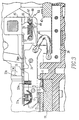
- the circuit breaker 1 includes a molded housing 3 forming compartments 5 for each of the poles 7 of the circuit breaker.
- the exemplary circuit breaker has three poles 7 a , 7 b and 7 c mounted side by side in the housing 3.
- Each pole 7 has a set of separable contacts 9 which includes a fixed main contact 11 and moveable main contact 13 as well as fixed and moveable arcing contacts 15 and 17, respectively.
- the fixed main contact is affixed to a line side conductor 19 which in turn is connected to the line stab 21 projecting through the bottom of the housing 3 for connection to a line conductor in a panel board (not shown).
- the fixed arcing contact 15 is affixed to a spacer 23 mounted on the line side conductor 19.
- the moveable main contact 13 and moveable arcing contact 17 are carried by a moveable contact support assembly 25.
- This assembly 25 includes a contact arm 27.
- the contact arm 27 includes a number of laminations 29m for the main contact and 29a for the arcing contact which are all pivotally mounted by a pin 31 in a downwardly facing U-shaped bracket 33.
- the moveable main contact 13 is affixed adjacent a first, free end 35m of the laminations 29 m while the moveable arcing contact 17 is similarly affixed to the end 35a of the laminations 29a.
- the moveable main contact 13 is biased by a main contact spring 37m about the pivot pin 31 against the fixed main contact 11.
- the arcing contact spring 37a applies contact pressure to the arcing contacts 15 and 17.
- Each of the laminations 29 is electrically connected to a stationary conductor lamination 39 by a flexible shunt 41.
- the stationary conductor laminations 39 are bolted to a load side conductor 43 which in turn is secured to a load side stab (not shown) which projects through the bottom of the housing in a manner similar to that of the line stab 21.
- the moveable contact support assembly 25 further includes a carrier 45.
- the carriers 45a and 45c for the contact support assemblies 25a, 25c of the outer poles each have a body 47 molded of an electrically insulative resin. Integrally molded with the body 47 are a pair of spaced apart downwardly and forwardly extending flanges 49, between which the contact arm 27 is pivotally connected by a pin 51 extending through the legs of the U-shaped bracket 33.
- a cross-bar 53 which in the exemplary embodiment is square in cross-section, extends through and rigidly connects the carriers of all of the poles.
- the carrier 45b of the contact support assembly 25b of the center pole instead of being molded of resin, is made of metal plates 46 which cantilever out from the cross-bar (into the plane of Figure 3) and are pivotally connected to lower toggle links 57 of an operating mechanism shown schematically at 59.
- the operating mechanism 59 can be manually or automatically (by a trip mechanism not shown) actuated to raise the lower toggle links 57 and rotate the carrier 45b. This also rotates the cross-bar 53 which is journalled in the housing 3 between the poles at 61 to simultaneously rotate the carriers 45a and 45c in the outer poles.
- rotation of the carrier 45a in the clockwise direction rotates the contact arm 27 to open the separable contacts 9.
- the contact arm 27 is coupled to the carrier 45 by a cam assembly 63 so that it rotates with it.
- the cam assembly 63 includes cam surfaces 65 on the rear edges of the U-shaped bracket 33, and a cam roller pin 67 which is guided at its ends in slots 69 in the flanges 49 on the carriers 45.
- the cam roller pin 67 is biased against the cam surface 65 by cam springs 71 connected to the pivot pin 51.
- the cam surfaces 65 have notches 73 in which the cam roller pin 67 is normally seated to couple the contact arm 27 to the carrier 45 for rotation therewith.
- the operating mechanism 59 requires time in order to respond to an overcurrent condition and open the contacts through rotation of the carriers 45. In the case of a short circuit, this allows the current to become very high by the time the contacts are separated. It can be very difficult to extinguish the resulting arc which is struck between the contacts, and in any event, this condition accelerates the wear on the contacts. It is common, therefore, to provide a blow open feature.
- This blow open feature is provided in the circuit breaker described in U.S. Patent No. 4,887,057 by the flexible shunts 41 and the cam assembly 63. As will be noted in Figures 1 and 3, the flexible shunts 41 are bent in the middle so that the current flows in partially opposing directions in the two halves of the shunt.
- U.S. Patent No. 4,887,057 addressed this problem by providing an energy absorber on a stop engaged by the contact arm at the blow open position.
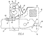
- This stop 75 is in the form of a pin 77 extending transversely above the contact arm and supporting a rubber sleeve 79.
- the pin 77 is supported by a U-shaped bracket 81 having a first set of legs 83.
- the bracket 81 also has a second set of legs 85 which pivotally support the pivot pin 51 on which the carriers 45 are mounted.
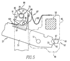
- a latching mechanism 87 is provided to mechanically retain the contact arm 27 in the blow open position.
- This latching mechanism 87 includes a latch hook 89 having an open slot 91 forming a pair of jaws 93.
- the latch hook 89 has a transverse pivot pin 95 which is rotatably supported in a U-shaped bracket 97 mounted on the top of the bracket 33 of the contact arm 27.
- a torsion spring 101 which engages the top of the arm 27 and a projection 99 on the latch hook, biases the latch hook angularly to a cocked position in which the jaws 93 are aligned for engagement with the stop member 75.
- a latch member in the form of a leaf spring 103 cantilevered from the carrier 45 holds the latch hook 89 against the bias provided by the torsion spring 101 to the latched position in which the jaws 93 mechanically engage the stop member 75 to prevent rebound of the contact arm 27 from the blow open position.
- the leaf spring 103 overrides the bias of the torsion 101 to retain the latch hook in the latched position.
- the cam roller pin 67 reengages the notches 73 in the cam surfaces 65 to recouple the contact arm 27 to the carrier 45 as shown in Figure 6.
- the leaf spring 103 is disengaged from the latch hook 89.
- the torsion spring 101 can then rotate the latch hook toward the cocked position which releases the jaws from the stop member 75 as the operating mechanism is used to reclose the contacts by rotating the contact back to the position of Figure 1.
- the contacts can be reclosed by the operating mechanism 59.
- the latching mechanism 87 is only provided on the outer poles 7a and 7c.
- the center pole is provided with a resilient stop of the type described in U.S. Patent No. 4,887,057, as positive interruption of current in the two phases switched by the outer poles is sufficient to terminate current flow in all three phases.
Landscapes
- Physics & Mathematics (AREA)
- Electromagnetism (AREA)
- Breakers (AREA)
Applications Claiming Priority (2)
| Application Number | Priority Date | Filing Date | Title |
|---|---|---|---|
| US975474 | 1997-11-20 | ||
| US08/975,474 US5912605A (en) | 1997-11-20 | 1997-11-20 | Circuit breaker with automatic catch to prevent rebound of blow open contact arm |
Publications (2)
| Publication Number | Publication Date |
|---|---|
| EP0918348A2 true EP0918348A2 (de) | 1999-05-26 |
| EP0918348A3 EP0918348A3 (de) | 2000-10-11 |
Family
ID=25523065
Family Applications (1)
| Application Number | Title | Priority Date | Filing Date |
|---|---|---|---|
| EP98121229A Withdrawn EP0918348A3 (de) | 1997-11-20 | 1998-11-06 | Leistungsschalter mit Automatischer Verriegelungsvorrichtung zur Verhinderung des Rückpralles von einem elektrodynamisch geöffneten Kontaktarm |
Country Status (6)
| Country | Link |
|---|---|
| US (1) | US5912605A (de) |
| EP (1) | EP0918348A3 (de) |
| CN (1) | CN1171268C (de) |
| CA (1) | CA2254427A1 (de) |
| ID (1) | ID21296A (de) |
| ZA (1) | ZA9810505B (de) |
Cited By (7)
| Publication number | Priority date | Publication date | Assignee | Title |
|---|---|---|---|---|
| WO2002043096A1 (de) * | 2000-11-24 | 2002-05-30 | Siemens Aktiengesellschaft | Antriebsstrang für einen bewegbaren kontakt eines elektrischen schalters |
| DE102005050980A1 (de) * | 2005-10-25 | 2007-04-26 | Moeller Gmbh | Kontaktsystem für einen Niederspannungsschalter |
| EP2251881A2 (de) * | 2009-05-15 | 2010-11-17 | Eaton Corporation | Trägheitsraste für einen Leistungsschalter eines automatischen Übertragungsschalters |
| EP2228810A3 (de) * | 2009-03-11 | 2014-01-08 | LS Industrial Systems Co., Ltd | Leistungsschalter mit Vorrichtung zur Verhinderung eines Rückschlags |
| EP2835814A1 (de) * | 2013-08-07 | 2015-02-11 | ABB S.p.A. | Schutzschalter |
| CN105719857A (zh) * | 2016-04-21 | 2016-06-29 | 环宇集团浙江高科有限公司 | 自动转换开关的防弹跳装置 |
| EP3104385A1 (de) * | 2015-06-11 | 2016-12-14 | General Electric Company | Haltevorrichtung für ein schutzschalterkontaktsystem |
Families Citing this family (13)
| Publication number | Priority date | Publication date | Assignee | Title |
|---|---|---|---|---|
| DE10049728C2 (de) * | 2000-09-28 | 2003-01-02 | Siemens Ag | Antriebsstrang für einen bewegbaren Kontakt eines elektrischen Schalters |
| US6614326B2 (en) | 2001-07-10 | 2003-09-02 | Eaton Corporation | Power-line coupler having a circuit breaker form or a panelboard employing the same |
| US6977568B1 (en) * | 2005-01-13 | 2005-12-20 | Eaton Corporation | Blow open moving contact assembly for electric power switching apparatus with a very high current interruption rating |
| US7351927B1 (en) * | 2006-10-13 | 2008-04-01 | Eaton Corporation | Electrical switch, conductor assembly, and independent flexible conductive elements therefor |
| US7646269B2 (en) * | 2007-03-07 | 2010-01-12 | Eaton Corporation | Electrical switching apparatus, and conductor assembly and shunt assembly therefor |
| CN102856086B (zh) * | 2011-06-29 | 2015-04-29 | 西门子公司 | 切换装置 |
| US8988175B2 (en) * | 2012-01-26 | 2015-03-24 | General Electric Company | Override device for a circuit breaker and methods of operating circuit breaker |
| US9208962B2 (en) * | 2013-11-26 | 2015-12-08 | General Electric Company | Circuit breaker including an anti-rebound system, anti-rebound system for a circuit breaker and method |
| US9349560B2 (en) | 2014-02-20 | 2016-05-24 | General Electric Company | Limiter type air circuit breaker with blow open arrangement |
| US9576753B2 (en) | 2015-06-16 | 2017-02-21 | General Electric Company | Moveable contact arm releases latch plate engagement in a circuit breaker |
| CN107068508B (zh) * | 2017-05-22 | 2019-08-27 | 浙江人民电器有限公司 | 一种断路器 |
| CN109559946A (zh) * | 2017-09-27 | 2019-04-02 | 常熟开关制造有限公司(原常熟开关厂) | 一种断路器 |
| CN117276021A (zh) * | 2022-06-15 | 2023-12-22 | 日立能源瑞士股份公司 | 防回弹保护装置及包括其的断路器 |
Family Cites Families (8)
| Publication number | Priority date | Publication date | Assignee | Title |
|---|---|---|---|---|
| GB756367A (en) * | 1953-09-25 | 1956-09-05 | English Electric Co Ltd | Improvements in and relating to latching devices |
| DE2552257C3 (de) * | 1975-11-21 | 1979-01-18 | Licentia Patent-Verwaltungs-Gmbh, 6000 Frankfurt | Leistungsschalter |
| JPS58131622A (ja) * | 1982-01-29 | 1983-08-05 | 三菱電機株式会社 | 気中しや断器 |
| US4733211A (en) * | 1987-01-13 | 1988-03-22 | General Electric Company | Molded case circuit breaker crossbar assembly |
| US4887057A (en) * | 1988-08-01 | 1989-12-12 | Westinghouse Electric Corp. | Cam roll pin assembly |
| US5341191A (en) * | 1991-10-18 | 1994-08-23 | Eaton Corporation | Molded case current limiting circuit breaker |
| US5363076A (en) * | 1993-04-28 | 1994-11-08 | Square D Company | Circuit breaker having spring biased blade suspension |
| US5793270A (en) * | 1996-09-03 | 1998-08-11 | Eaton Corporation | Circuit breaker with latch preventing rebound of blow open contact arm |
-
1997
- 1997-11-20 US US08/975,474 patent/US5912605A/en not_active Expired - Fee Related
-
1998
- 1998-11-06 EP EP98121229A patent/EP0918348A3/de not_active Withdrawn
- 1998-11-12 ID IDP981478A patent/ID21296A/id unknown
- 1998-11-17 ZA ZA9810505A patent/ZA9810505B/xx unknown
- 1998-11-18 CA CA002254427A patent/CA2254427A1/en not_active Abandoned
- 1998-11-20 CN CNB98122539XA patent/CN1171268C/zh not_active Expired - Fee Related
Cited By (14)
| Publication number | Priority date | Publication date | Assignee | Title |
|---|---|---|---|---|
| WO2002043096A1 (de) * | 2000-11-24 | 2002-05-30 | Siemens Aktiengesellschaft | Antriebsstrang für einen bewegbaren kontakt eines elektrischen schalters |
| US6831240B2 (en) | 2000-11-24 | 2004-12-14 | Siemens Aktiengesellschaft | Drive train for a displaceable contact on an electrical power breaker |
| DE102005050980A1 (de) * | 2005-10-25 | 2007-04-26 | Moeller Gmbh | Kontaktsystem für einen Niederspannungsschalter |
| DE102005050980B4 (de) * | 2005-10-25 | 2007-11-08 | Moeller Gmbh | Kontaktsystem für einen Niederspannungsschalter |
| EP2228810A3 (de) * | 2009-03-11 | 2014-01-08 | LS Industrial Systems Co., Ltd | Leistungsschalter mit Vorrichtung zur Verhinderung eines Rückschlags |
| EP2251881A2 (de) * | 2009-05-15 | 2010-11-17 | Eaton Corporation | Trägheitsraste für einen Leistungsschalter eines automatischen Übertragungsschalters |
| EP2835814A1 (de) * | 2013-08-07 | 2015-02-11 | ABB S.p.A. | Schutzschalter |
| CN104347324A (zh) * | 2013-08-07 | 2015-02-11 | Abb公司 | 断路器 |
| US9384912B2 (en) | 2013-08-07 | 2016-07-05 | Abb S.P.A. | Circuit breaker |
| CN104347324B (zh) * | 2013-08-07 | 2018-11-23 | Abb公司 | 断路器 |
| EP3104385A1 (de) * | 2015-06-11 | 2016-12-14 | General Electric Company | Haltevorrichtung für ein schutzschalterkontaktsystem |
| CN106252169A (zh) * | 2015-06-11 | 2016-12-21 | 通用电气公司 | 用于电路断路器触点系统的固持组件 |
| CN106252169B (zh) * | 2015-06-11 | 2019-09-03 | Abb瑞士股份有限公司 | 用于电路断路器触点系统的固持组件 |
| CN105719857A (zh) * | 2016-04-21 | 2016-06-29 | 环宇集团浙江高科有限公司 | 自动转换开关的防弹跳装置 |
Also Published As
| Publication number | Publication date |
|---|---|
| CA2254427A1 (en) | 1999-05-20 |
| CN1171268C (zh) | 2004-10-13 |
| ID21296A (id) | 1999-05-20 |
| ZA9810505B (en) | 1999-05-24 |
| EP0918348A3 (de) | 2000-10-11 |
| CN1227396A (zh) | 1999-09-01 |
| US5912605A (en) | 1999-06-15 |
Similar Documents
| Publication | Publication Date | Title |
|---|---|---|
| US5912605A (en) | Circuit breaker with automatic catch to prevent rebound of blow open contact arm | |
| US5793270A (en) | Circuit breaker with latch preventing rebound of blow open contact arm | |
| US4611187A (en) | Circuit breaker contact arm latch mechanism for eliminating contact bounce | |
| US4679016A (en) | Interchangeable mechanism for molded case circuit breaker | |
| US4255732A (en) | Current limiting circuit breaker | |
| US6015959A (en) | Molded case electric power switches with cam driven, spring powered open and close mechanism | |
| JPS6286632A (ja) | 回路遮断器 | |
| JP2002517064A (ja) | 高アンペア定格遮断器の回転式接点集成体 | |
| US6204465B1 (en) | Circuit breaker with arc gas engaging paddles on a trip bar and/or crossbar | |
| US5290982A (en) | Circuit breaker with positive on/off interlock | |
| CA2364989C (en) | Circuit breaker with bypass conductor commutating current out of the bimetal during short circuit interruption and method of commutating current out of bimetal | |
| US6376788B1 (en) | Magnetically collapsible toggle linkage for electrical switching apparatus | |
| CA1167495A (en) | Multipole electric circuit breaker with improved current limiting device | |
| US4281303A (en) | Individual circuit breaker pole trip mechanism | |
| US6590482B2 (en) | Circuit breaker mechanism tripping cam | |
| JP2000057928A (ja) | 回路遮断器 | |
| US5931289A (en) | Circuit breaker with quick closing mechanism | |
| JP3814671B2 (ja) | 回路遮断器 | |
| JPH0119313Y2 (de) | ||
| US6489867B1 (en) | Separating pins for the shunt wires of a circuit breaker | |
| US3849619A (en) | Circuit breaker with reverse override device | |
| US4731921A (en) | Method of fabricating a molded case circuit breaker | |
| US6819205B2 (en) | Current limiting low-voltage power circuit breaker | |
| US4551697A (en) | Current limiting circuit breaker mechanism | |
| AU2011360876B2 (en) | An improved operating mechanism for circuit breaker |
Legal Events
| Date | Code | Title | Description |
|---|---|---|---|
| PUAI | Public reference made under article 153(3) epc to a published international application that has entered the european phase |
Free format text: ORIGINAL CODE: 0009012 |
|
| AK | Designated contracting states |
Kind code of ref document: A2 Designated state(s): DE FR GB IT |
|
| AX | Request for extension of the european patent |
Free format text: AL;LT;LV;MK;RO;SI |
|
| RIN1 | Information on inventor provided before grant (corrected) |
Inventor name: EBERTS, WIILIAM, GEORGE |
|
| PUAL | Search report despatched |
Free format text: ORIGINAL CODE: 0009013 |
|
| AK | Designated contracting states |
Kind code of ref document: A3 Designated state(s): AT BE CH CY DE DK ES FI FR GB GR IE IT LI LU MC NL PT SE |
|
| AX | Request for extension of the european patent |
Free format text: AL;LT;LV;MK;RO;SI |
|
| RIC1 | Information provided on ipc code assigned before grant |
Free format text: 7H 01H 77/10 A, 7H 01H 71/50 B |
|
| 17P | Request for examination filed |
Effective date: 20010312 |
|
| AKX | Designation fees paid |
Free format text: DE FR GB IT |
|
| GRAP | Despatch of communication of intention to grant a patent |
Free format text: ORIGINAL CODE: EPIDOSNIGR1 |
|
| RIN1 | Information on inventor provided before grant (corrected) |
Inventor name: EBERTS, WILLIAM, GEORGE |
|
| STAA | Information on the status of an ep patent application or granted ep patent |
Free format text: STATUS: THE APPLICATION IS DEEMED TO BE WITHDRAWN |
|
| 18D | Application deemed to be withdrawn |
Effective date: 20040228 |