EP0918428A2 - Procédé et dispositif pour système de surveillance de sécurité - Google Patents
Procédé et dispositif pour système de surveillance de sécurité Download PDFInfo
- Publication number
- EP0918428A2 EP0918428A2 EP98660102A EP98660102A EP0918428A2 EP 0918428 A2 EP0918428 A2 EP 0918428A2 EP 98660102 A EP98660102 A EP 98660102A EP 98660102 A EP98660102 A EP 98660102A EP 0918428 A2 EP0918428 A2 EP 0918428A2
- Authority
- EP
- European Patent Office
- Prior art keywords
- connection
- transmission path
- alarm
- security
- control information
- Prior art date
- Legal status (The legal status is an assumption and is not a legal conclusion. Google has not performed a legal analysis and makes no representation as to the accuracy of the status listed.)
- Withdrawn
Links
- 238000000034 method Methods 0.000 title claims abstract description 20
- 230000005540 biological transmission Effects 0.000 claims abstract description 22
- 238000012544 monitoring process Methods 0.000 claims description 17
- 230000003287 optical effect Effects 0.000 claims description 2
- 230000001360 synchronised effect Effects 0.000 claims 1
- 238000012546 transfer Methods 0.000 description 6
- 238000005516 engineering process Methods 0.000 description 3
- 230000008901 benefit Effects 0.000 description 2
- 230000000903 blocking effect Effects 0.000 description 2
- 238000010586 diagram Methods 0.000 description 2
- 238000012545 processing Methods 0.000 description 2
- 230000011664 signaling Effects 0.000 description 2
- 238000013459 approach Methods 0.000 description 1
- 230000002457 bidirectional effect Effects 0.000 description 1
- 238000007796 conventional method Methods 0.000 description 1
- 230000001419 dependent effect Effects 0.000 description 1
- 238000001514 detection method Methods 0.000 description 1
- 238000011161 development Methods 0.000 description 1
- 230000008569 process Effects 0.000 description 1
- 230000004044 response Effects 0.000 description 1
- 238000012360 testing method Methods 0.000 description 1
- 230000001960 triggered effect Effects 0.000 description 1
Images
Classifications
-
- H—ELECTRICITY
- H04—ELECTRIC COMMUNICATION TECHNIQUE
- H04Q—SELECTING
- H04Q11/00—Selecting arrangements for multiplex systems
- H04Q11/04—Selecting arrangements for multiplex systems for time-division multiplexing
- H04Q11/0428—Integrated services digital network, i.e. systems for transmission of different types of digitised signals, e.g. speech, data, telecentral, television signals
- H04Q11/0435—Details
- H04Q11/0457—Connection protocols
-
- H—ELECTRICITY
- H04—ELECTRIC COMMUNICATION TECHNIQUE
- H04M—TELEPHONIC COMMUNICATION
- H04M11/00—Telephonic communication systems specially adapted for combination with other electrical systems
- H04M11/04—Telephonic communication systems specially adapted for combination with other electrical systems with alarm systems, e.g. fire, police or burglar alarm systems
Definitions
- the present invention relates to a method according to the preamble of claim 1 for providing a security service.
- the present invention also concerns an apparatus for security service use.
- security service refers to a comprehensive entity offered by a security service provider for continuous monitoring of the premises or other specific objects of a customer against different types of special and emergency hazards.
- Typical services include, e.g., alarm transfer with a nationwide and/or local coverage and a message transfer service.
- the services comprise such functions as a supervised transmission path from the customer premises to the alarm center (security service provider, police, fire brigade or the like).
- the security service provider takes the responsibility of maintaining the entire transmission path and assuring a continuous 24-hour service availability.
- a network solution adapted for security services may be expected to have at least the following basic properties:
- network condition monitoring can be implemented at a reasonable cost by utilizing the monitoring function existing in switching centers.
- the switching center performs condition monitoring of ISDN lines and network terminal equipment by means of a so-called continuity test at about half-hour intervals.
- this is an excessively long delay period.
- DE Pat. Appl. No. 44 07 046 discloses an embodiment having the customer end provided with equipment capable of transmitting bit-stream data over a digital ISDN connection for the purpose of monitoring the availability of the connection. This embodiment is based on the concept that the customer-end equipment attempts to set up a connection to the security service provider and when the called party detects from the B-number signalling that the calling party is the customer proper, the process of setting up a connection is terminated. Conversely, if the security service provider finds a deviation in the preset rate of these call attempts, an alarm is triggered. To accomplish this function, extremely complicated and expensive equipment are needed at the customer end.
- the goal of the invention is achieved by virtue of utilizing the connection monitoring facility of the OSI protocol for layer 1 transmission between the switching center and the customer ISDN terminal that is available as a continuous standard function from the switching center side.
- the method according to the invention is implemented by sending continuous bit-stream data in a connectionless manner between the switching center and the customer network terminal, thus making it possible to achieve an almost realtime continuity monitoring of the connection.
- the U-interface of the connection is provided with a switch serving to disconnect the connection under the control of the alarm equipment in the case that the line is busy and the alarm equipment senses an alarm situation.
- the invention offers significant benefits.
- the switching time of a digital telephone network is not greater than 1 second.
- the connection of a network connection is so fast that the delay remains insignificant to the overall function of an alarm system.
- the overall switching time from triggering an alarm signal to its reception is in fact more related to the types of terminal equipment actually used and their technical implementations.
- the present invention makes it possible to expand the applications of ISDN technology in an entirely novel fashion.
- the potential of the new service concept can be expected to be extremely good provided that the charging rates of its availability are kept within reason.
- the novel concept may be seen as a first of a kind intended for wide distribution, including consumer marketing, of a security service product based on a realtime-monitored network solution.
- the embodiment disclosed herein has a distinct benefit by being able to use the existing network infrastructure and offering compatibility with standard equipment.
- other commercially marketed solutions of equivalent functionality are either based on expensive dedicated network arrangements or require a much higher level of performance from the terminal equipment.
- ISDN techniques make it possible to avail of the basic characteristics of a digital telephone network in security services including the network's reliable fast-rate data transmission properties, rapid switching times and the facility of using a single line for a plurality of simultaneous connections.
- the solution according to the invention is capable of fulfilling all the above-described basic needs of security services, simultaneously offering a plurality of novel service features. Owing to the high data transmission capacity of an ISDN connection, the level of service may be improved in the future by adding such elements as the transmission of a video signal and others.
- the condition of the ISDN connection is supervised from the switching center side by monitoring the frame transmission of the physical layer 1 at the U-interface. While the delay in the triggering of an alarm by the network monitoring program for a connection failure is dependent on the switching center technology used, specifications issued by manufacturers of such equipment typically give figures in the order of about 10 s.
- the monitoring of the U-interface is implemented by setting the layer 1 transmission according to the OSI protocol into a continuously active state from the switching center side. Then the switching center can perform condition monitoring on the state of the connection. Hence, tampering by severing the line or disconnecting the terminal equipment will trigger an essentially realtime alarm.
- the alarm processing program of the switching center is complemented with a data base containing information on all the connections included in the provided security service. With the help of a dedicated program, data related to security service customers can be screened from the stream of alarms and transferred to a special treatment. All the screened alarms are also recorded automatically in a log for later processing.
- an ISDN terminal has no means within the constraints of a normal ISDN signalling scheme to clear such B-channel connection that have not been set up by the terminal equipment itself. Hence, also herein it is possible to set up a blocking situation which obviously is most undesirable in terms of an alarm situation.
- the alarm equipment can as needed reinitiate the transmission of the alarm as soon as the interface is reconnected. In a number of cases this feature may be redundant, since the disconnection of the line alone is sufficient for issuing an alarm.
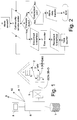
- a security survellance system 2 is shown having a plurality of sensors 1 connected thereto for the purpose of, e.g., monitoring break-in tampering of windows.
- the security surveillance system 2 may comprise, e.g., a conventional alarm sensor system/robotic telephone caller equipped with required facilities, or alternatively, it can be a specific ISDN-based alarm system offering an equivalent level of functionality.
- the alarm sensor system 2 is interfaced via an a/b adapter to the ISDN terminal equipment 3. Alarm transfer from the customer premises is forwarded in a conventional manner over the B-channel in the same fashion as in an analog connection.
- the terminal equipment 3 in turn is connected to the U-interface of the ISDN terminal equipment, which is also complemented with a disconnecting device 4, typically a relay.
- the disconnecting device 4 is controlled by means of the security surveillance system 2 so that, at the detection of an alarm signal under a situation having both voice lines busy, the disconnecting device 4 is opened at least temporarily, whereby an alarm is issued due to disconnection of the line at least by the automatic condition monitoring of the connection to a supervisory control computer 6 which is accessible via the normal telephone network 5.
- the control computer 6 is provided with a display 8 suitable for indicating the alarms and a data base 7 containing information on which the control computer can perform the desired actions 9, 10 and 11 according to the situation and type of alarm at the monitored object.
- the alarm may be transferred directly to a security services provider 9 (such as a security firm, an official or the like) or to an operator control room 10, wherefrom it may be further routed to, e.g., a GSM short message service or a faxing service 11.
- a security services provider 9 such as a security firm, an official or the like
- an operator control room 10 wherefrom it may be further routed to, e.g., a GSM short message service or a faxing service 11.
- the disconnecting device 4 such as a relay can be replaced by a solid-state switch or optical switch as is appropriate in the technology used.
- the U-interface is disconnected by the disconnecting device 4.
- the duration of the disconnect period is determined in block 27, and the switch is reclosed in block 28, whereafter a delay is set up by block 29 before the operation is returned to block 21 for a repeated attempt to call the alarm control center 6.
Landscapes
- Engineering & Computer Science (AREA)
- Signal Processing (AREA)
- Computer Networks & Wireless Communication (AREA)
- Telephonic Communication Services (AREA)
Applications Claiming Priority (2)
| Application Number | Priority Date | Filing Date | Title |
|---|---|---|---|
| FI973935 | 1997-10-10 | ||
| FI973935A FI105380B (fi) | 1997-10-10 | 1997-10-10 | Menetelmä ja laitteisto turvapalvelua varten |
Publications (1)
| Publication Number | Publication Date |
|---|---|
| EP0918428A2 true EP0918428A2 (fr) | 1999-05-26 |
Family
ID=8549709
Family Applications (1)
| Application Number | Title | Priority Date | Filing Date |
|---|---|---|---|
| EP98660102A Withdrawn EP0918428A2 (fr) | 1997-10-10 | 1998-10-09 | Procédé et dispositif pour système de surveillance de sécurité |
Country Status (2)
| Country | Link |
|---|---|
| EP (1) | EP0918428A2 (fr) |
| FI (1) | FI105380B (fr) |
-
1997
- 1997-10-10 FI FI973935A patent/FI105380B/fi active
-
1998
- 1998-10-09 EP EP98660102A patent/EP0918428A2/fr not_active Withdrawn
Also Published As
| Publication number | Publication date |
|---|---|
| FI105380B (fi) | 2000-07-31 |
| FI973935L (fi) | 1999-06-30 |
| FI973935A0 (fi) | 1997-10-10 |
Similar Documents
| Publication | Publication Date | Title |
|---|---|---|
| US6067346A (en) | Method and system for providing redundancy in security systems served by a public switched telephone network | |
| JP2981075B2 (ja) | 通信方法および交換機 | |
| EP0755602B1 (fr) | Systeme de telemesure | |
| US6263050B1 (en) | Method and system for responding to security system breaches via a wireless network | |
| EP0918428A2 (fr) | Procédé et dispositif pour système de surveillance de sécurité | |
| US5436959A (en) | Communication terminal having functions of detecting and preventing line branch | |
| JP2973768B2 (ja) | 電話を利用したガスメータ弁開方法 | |
| EP0756795B1 (fr) | Reseaux de telecommunications | |
| JP4414628B2 (ja) | 少なくとも1つの加入者線を監視する方法および監視システム | |
| JPS6068499A (ja) | 非常通報応答システム | |
| JP3295861B2 (ja) | 集中監視システム | |
| JP3107647B2 (ja) | 異常通報装置 | |
| TW199950B (en) | Remotely initiated telemetry calling system | |
| CA2095668C (fr) | Dispositif d'acces pour la telemetrie | |
| EP1028582A2 (fr) | Méthode et système de détection de trou de sécurité par l'utilisation d'équipement de télécommunication | |
| JP2000251179A (ja) | 独居老人安否確認装置 | |
| JPH0329556A (ja) | 自動通報装置 | |
| JP2000149175A (ja) | 警備システム | |
| JPS62232250A (ja) | 監視システム | |
| JPH0716214B2 (ja) | 発呼可能確認方法及びその装置 | |
| JPH04185042A (ja) | Isdnターミナルアダプタ | |
| JPH03167953A (ja) | データ通信システム | |
| JPH1168983A (ja) | 加入者側からセンタへのデータ転送方法、並びにデータ転送用端末機器 | |
| JPH01319357A (ja) | 加入者回線断線検出通知方式 | |
| JPS6052151A (ja) | 音声使用優先型電話交換機 |
Legal Events
| Date | Code | Title | Description |
|---|---|---|---|
| PUAI | Public reference made under article 153(3) epc to a published international application that has entered the european phase |
Free format text: ORIGINAL CODE: 0009012 |
|
| AK | Designated contracting states |
Kind code of ref document: A2 Designated state(s): AT BE CH CY DE DK ES FI FR GB GR IE IT LI LU MC NL PT SE |
|
| AX | Request for extension of the european patent |
Free format text: AL;LT;LV;MK;RO;SI |
|
| STAA | Information on the status of an ep patent application or granted ep patent |
Free format text: STATUS: THE APPLICATION IS DEEMED TO BE WITHDRAWN |
|
| 18D | Application deemed to be withdrawn |
Effective date: 20040501 |