EP0918437A1 - Decodeur et procede de decodage de signaux d'informations - Google Patents
Decodeur et procede de decodage de signaux d'informations Download PDFInfo
- Publication number
- EP0918437A1 EP0918437A1 EP98924598A EP98924598A EP0918437A1 EP 0918437 A1 EP0918437 A1 EP 0918437A1 EP 98924598 A EP98924598 A EP 98924598A EP 98924598 A EP98924598 A EP 98924598A EP 0918437 A1 EP0918437 A1 EP 0918437A1
- Authority
- EP
- European Patent Office
- Prior art keywords
- pictures
- decoded
- motion
- data
- decoding
- Prior art date
- Legal status (The legal status is an assumption and is not a legal conclusion. Google has not performed a legal analysis and makes no representation as to the accuracy of the status listed.)
- Withdrawn
Links
Images


Classifications
-
- H—ELECTRICITY
- H04—ELECTRIC COMMUNICATION TECHNIQUE
- H04N—PICTORIAL COMMUNICATION, e.g. TELEVISION
- H04N5/00—Details of television systems
- H04N5/76—Television signal recording
- H04N5/91—Television signal processing therefor
- H04N5/92—Transformation of the television signal for recording, e.g. modulation, frequency changing; Inverse transformation for playback
-
- H—ELECTRICITY
- H04—ELECTRIC COMMUNICATION TECHNIQUE
- H04N—PICTORIAL COMMUNICATION, e.g. TELEVISION
- H04N21/00—Selective content distribution, e.g. interactive television or video on demand [VOD]
- H04N21/40—Client devices specifically adapted for the reception of or interaction with content, e.g. set-top-box [STB]; Operations thereof
- H04N21/43—Processing of content or additional data, e.g. demultiplexing additional data from a digital video stream; Elementary client operations, e.g. monitoring of home network or synchronising decoder's clock; Client middleware
- H04N21/44—Processing of video elementary streams, e.g. splicing a video clip retrieved from local storage with an incoming video stream or rendering scenes according to encoded video stream scene graphs
- H04N21/44016—Processing of video elementary streams, e.g. splicing a video clip retrieved from local storage with an incoming video stream or rendering scenes according to encoded video stream scene graphs involving splicing one content stream with another content stream, e.g. for substituting a video clip
-
- H—ELECTRICITY
- H04—ELECTRIC COMMUNICATION TECHNIQUE
- H04N—PICTORIAL COMMUNICATION, e.g. TELEVISION
- H04N21/00—Selective content distribution, e.g. interactive television or video on demand [VOD]
- H04N21/40—Client devices specifically adapted for the reception of or interaction with content, e.g. set-top-box [STB]; Operations thereof
- H04N21/43—Processing of content or additional data, e.g. demultiplexing additional data from a digital video stream; Elementary client operations, e.g. monitoring of home network or synchronising decoder's clock; Client middleware
- H04N21/4302—Content synchronisation processes, e.g. decoder synchronisation
- H04N21/4307—Synchronising the rendering of multiple content streams or additional data on devices, e.g. synchronisation of audio on a mobile phone with the video output on the TV screen
- H04N21/43072—Synchronising the rendering of multiple content streams or additional data on devices, e.g. synchronisation of audio on a mobile phone with the video output on the TV screen of multiple content streams on the same device
Definitions
- the present invention relates to a device for decoding video data and audio data and its method, and specifically relates to special reproduction techniques for video data.
- a technique for encoding video signals and audio signals for television using an encoding technique such as an MPEG (moving picture experts group) or the like, and transmitting or recording/reproducing them, will be generalized.
- the above MPEG is constructed so that decoding and displaying timings of a video signal and an audio signal are synchronized using time stamps added to them bit streams, in a decoder at a receiving side or a reproducing side. And if video is frozen in the decoder, audio is muted because the timings cannot be synchronized using the time stamps.
- the present invention aims to output audio even if video is frozen in an MPEG decoder or the like. Furthermore, the present invention aims to output a motion picture by returning immediately after a release from freeze. Moreover, the present invention aims to synchronize video with audio immediately after a release from freeze.
- an information signal decoding method of the present invention plural areas to store decoded motion picture data are prepared. Freeze and continuous output of the motion picture data are performed using one of said plural areas. Intraframe predicted pictures and forward predicted pictures in a data stream of motion pictures to be inputted in said freeze are decoded using the other areas. A data stream of audio is decoded while keeping a synchronous relationship with motion pictures.
- channel switching is prepared by decoding the data stream of motion pictures of a channel different from the frozen motion picture, and either of the frozen motion picture or the motion picture of the different channel is selected to selectively switch a channel.
- An information signal decoding device provides a first decoding means for decoding a data stream of motion pictures, a second decoding means for decading a data stream of audio, a motion picture data storing means having plural areas to store the decoded motion picture data, and a control means for synchronizing the decoding of motion picture data and the decoding of audio data.
- freeze and continuous output of motion picture data are performed using one of said plural areas, and intraframe predicted pictures and forward predicted pictures in a data stream of motion pictures to be inputted in a freeze are decoded using the other areas.
- a data stream of audio is decoded while keeping a synchronous relationship with said motion pictures.
- the information signal decoding device further comprises a switching means for switching said plural areas for output, and a selecting means for selecting an area to be switched by the above switching means, to selectively switch a channel.
- intraframe predicted pictures and forward predicted pictures in a data stream of motion pictures are decoded using the other areas, and the decoded motion picture data is outputted to said single area as a reduced picture.
- An information signal decoding device comprises a decoding means for decoding a data stream of motion pictures, a motion picture data storing means having plural areas to store decoded motion picture data, and a picture reducing means for generating reduced picture data from the decoded motion picture data.
- a decoding means for decoding a data stream of motion pictures
- a motion picture data storing means having plural areas to store decoded motion picture data
- a picture reducing means for generating reduced picture data from the decoded motion picture data.
- freeze and continuous output of motion picture data are performed using one of plural areas in a motion picture storing means, and intraframe predicted pictures and forward predicted pictures in a data stream of motion pictures to be inputted in a freeze are decoded using the other areas.
- a data stream of audio is decoded while keeping a synchronous relationship with motion pictures.
- intraframe predicted pictures and forward predicted pictures in a data stream of motion pictures are decoded using the other areas, and the decoded motion picture data is outputted to said single area as a reduced picture.
- the function of special effects such as strobe reproduction, channel scanning, etc., can be realized.
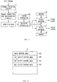
- Fig. 1 is a block diagram showing the configuration of a data decoding device to which the present invention is applied.
- bit stream data is data reproduced from a recording medium such as a DVD or the like or data received from a digital broadcasting tuner or the like.
- a channel decoding circuit 1 performs channel decoding of the bit stream data.
- An error correcting and descrambling circuit 2 performs error correction and descrambling to output data from the channel decoding circuit 1.
- a demultiplexer 3 separates a bit stream of prescribed one or more channels from output data of the error correcting and descrambling circuit 2.
- a decoding controller 4 controls the decoding of a video decoder 6 and an audio decoder 7.
- a timing generator 5 generates a timing signal to be used by the decoding controller 4.
- the video decoder 6 decodes video data from the bit stream of video data utilizing a memory 8.
- the audio decoder 7 decodes audio data from the bit stream of audio data by means of memory 9.
- Fig. 2 shows areas in the memory 8 of Fig. 1.
- an input buffer area 8A and a first to a third output buffer areas 8B to 8D are provided.
- the input buffer area 8A video data to be outputted from the decoding controller 4 before decoding is stored.
- the first to the third output buffer areas 8B to 8D each decoded video data is stored respectively.
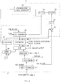
- Fig. 3 is a block diagram showing the configuration of the decoding controller 4 and the timing generator 5.
- a PES (packetized elementary stream) packet supplied from the demultiplexer 3 is transmitted to a PES purser 42 via an input interface 41.
- a PCR (program clock reference) or an SCR (system clock reference) is transmitted to an STC counter 46 and a differencer 51.
- the difference between the PCR value or the SCR value and the value of the STC counter 46 is obtained in the differencer 51.
- This difference value is converted into an analog signal by a D/A converter 52 to control a VCO (voltage control oscillator) 54 via a filter 53.
- An oscillation frequency of this VCO 54 is set to 29.97 Hz in an NTSC system, and 25 Hz in a PAL system.
- This output of the VCO 54 is set as the reference clock of the STC counter 46 in order to completely synchronize the operation of whole decoder with timing on a transmitting side.
- the PCR or the SCR code is loaded to the STC counter 46 at the moment when the PCR or the SCR reaches the decoding controller 4, presetting is completed at the time when the last byte of the PCR or the SCR is loaded into the STC counter 46, and count-up is started at the output clock of the VCO 54 from the next moment.
- a PES packet supplied via the input interface 41 is separated into a PES header part and a payload part in the PES purser 42. Then, a DTS (decoding time stamp) and a PTS (presentation time stamp) are extracted from the PES header part.
- the DTS and the PTS of video data are stored in registers 43-1 and 43-2 respectively, and the PTS of audio data is stored in a register 43-3.
- the video data and the audio data which are the payload parts are supplied to the video decoder 6 and the audio decoder 7 respectively.
- the DTS and the PTS stored in the registers 43-1 to 43-3 are individually compared with the value of the STC counter 46 in comparators 45-1 to 45-3, respectively.
- a command to start decoding the I-pictures or the P-pictures of the video data is outputted.
- a command to start displaying the I-pictures or the P-pictures of the video data or a command to start decoding B-pictures is outputted.
- a command to start decoding the audio data is outputted.
- the DTS and the PTS do not always exist in each picture, they are needed to synchronize with the vertical synchronizing period of a video signal in the decoding controller 4 to perform decoding or displaying of the video data in a prescribed order according to the construction of a GOP (group of picture). Then, referring to Fig. 3, the value of the STC counter 46 is latched onto the register 47 at the timing of the vertical synchronizing signal outputted from a synchronizing signal generator 55. And the output of a register 49 in a unit of 90 KHz and having a value corresponding to one frame unit (3003 in the NTSC system, and 3600 in the PAL system) and the output of the register 47 are added by an adder 48 to complement the time stamps.
- Fig. 4 shows the flow of input/output video data in the video decoder 6 in normal reproduction.
- the video data supplied from the demultiplexer 3 is stored in the input buffer area 8A in the memory 8. It is read out at the prescribed timing described with reference to Fig. 3 and decoded by a decoding part 66. Then, the decoded data is stored in one of the first to the third output buffer areas 8B to 8D in the memory 8 according to picture type. The stored data is read out from the output buffer area at the prescribed timing and outputted to the outside of the video decoder 6.
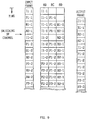
- Fig. 5 shows an example of the timing relationship among input video data to the video decoder 6, video data stored in the memory 8 and output video data therefrom, in normal reproduction.
- input frames show the frames of the video data to be inputted to the video decoder 6
- output frames show the frames of the video data to be outputted from the video decoder 6.
- 8B, 8C and 8D show the frames of the video data stored in the first output buffer area 8B, the second output buffer area 8C and the third output buffer area 8D, respectively.
- a first I-picture (I1) is first inputted, decided and stored in the first output buffer area 8B.
- a first P-picture (P1) is inputted, decoded and stored in the second output buffer area 8C.
- P1 For this decoding of P1, I1 stored in the first output buffer area 8B is used.
- a first B-picture (B1) is inputted, decoded and stored in the third output buffer area 8D.
- B1 stored in the first output buffer area 8B and P1 stored in the second output buffer area 8C are used.
- a second B-picture (B2) is inputted, decoded and stored in the third output buffer area 8D is stored.
- Input frames are decoded and stored hereafter in the similar.
- the data thus stored in the first to the third output buffer areas are outputted in the sequence of I1, B1, B2, P1, B3, B4, P2, ....
- Fig. 6 shows the flow of input/output video data in the video decoder 6 when video data is frozen.
- Video data supplied from the demultiplexer 3 is stored in the input buffer area 8A in the memory 8.
- the stored data is read out at the prescribed timing and decoded by the decoding part 66.
- I-pictures of that are stored in the first output buffer area 8B
- P-pictures of that are stored in the first output buffer area 8B or the second output buffer area 8C.
- B-pictures of that are not stored in the input buffer area 8A or not decoded even if stored, they are not stored in the third output buffer area 8D.
- the video data stored in the first output buffer area 8B and the second output buffer area 8C are not outputted to the outside of the video decoder 6, they are not displayed on a monitor or the like.
- the video data decoded before frozen and stored in the third output buffer area 8D are repeatedly outputted. At this time, since decoding and output of audio data are continued, audio is reproduced similar to the time of normal reproduction even if video is frozen. If the freeze is released, decoding of the video data is immediately started. Since the decoded I- and P-pictures are stored in the first output buffer area 8B and the second output buffer area 8C even under freezing, the video data can be outputted immediately after the freeze is released.
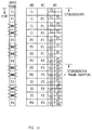
- Fig. 7 shows an example of the timing relationship among input video data to the video decoder 6, video data to be stored in the memory 8 and output video data from the video decoder 6, when video data is frozen.
- the operation until a freeze command is given from a user and the operation after a release from freeze in Fig. 7 are similar to the operation in normal reproduction shown in Fig. 5.
- the video data stored in the third output buffer area 8D (it is B2 in this embodiment) is repeatedly outputted.
- the I- and the P-pictures to be inputted are sequentially decoded and alternately stored in the first output buffer area 8B and the second output buffer area 8C. If the freeze is released when B12 is inputted, B12 is decoded using P4 and P5 stored in the first output buffer area 8B and the second output buffer area 8C, and the decoded B12 is stored in the third output buffer area 8D.
- the third output buffer area 8D is frozen but the first output buffer 8B or the second output buffer area 8C may be frozen.
- Fig. 8 shows the flow of input/output video data in the video decoder 6 when the channel of video data is switched.
- the video data to be inputted here to the video decoder 6 is switched by a user's command. This switching is conducted by the demultiplexer 3, for example.
- Video data supplied from the demultiplexer 3 is stored in the input buffer area 8A in the memory 8. It is read out at the prescribed timing and decoded by the decoding part 66. I-pictures are stored in the first output buffer area 8B, and P-pictures are stored in the first output buffer area 8B or the second output buffer area 8C. Since B-pictures are not stored in the input buffer area 8A or not decoded even if stored, they are not stored in the third output buffer area 8D.
- the video data decoded before channel switching and stored in the third output buffer area 8D are repeatedly outputted.
- a switch 67 whether to output the video data stored in the third output buffer area 8D from the video decoder 6 before channel switching or to output the video data stored in the first output buffer area 8B and the second output buffer area 8C from the video decoder 6 after channel switching can be selected.
- Fig. 9 shows an example of the timing relationship among input video data to the video decoder 6, video data to be stored in the memory 8 and output video data from the video decoder 6 when the channel of video data is switched. In this embodiment, it is assumed that the channel is switched from 1 to 2. In Fig. 9, numerical numbers added to "-" after picture numbers show channel numbers.
- the operation before channel switching in Fig. 9 is similar to the operation in normal reproduction shown in Fig. 5.
- the I- and the P-pictures of the channel 2 are sequentially decoded and alternately stored in the first output buffer area 8B and the second output buffer area 8C.
- the stored data are outputted from the video decoder 6 through the switch 67.
- Fig. 10 shows the flow of input/output video data in the video decoder 6 in strobe reproduction and [strobe reproduction + framing reproduction].
- video data supplied from the demultiplexer 3 is stored in the input buffer area 8A in the memory 8. It is read out at the specified timing and decoded by the decoding part 66.
- decoded I-pictures are stored in the first output buffer area 8B
- the P-pictures are stored in the first output buffer area 8B or the second output buffer area 8C. Since the B-pictures are not stored in the input buffer area 8A or not decoded even if stored, they are not stored in the third output buffer area 8D.
- the video data stored in the first output buffer area 8B and the video data stored in the second output buffer area 8C are read out at the prescribed timing, subjected to size reduction processing by a filter 68, and then, it is written in the third output buffer area 8D.
- the stored data is read out at the prescribed timing and outputted from the video decoder 6.
- Fig. 11 is a diagram showing an example of the timing relationship between input video data to the video decoder 6 and video data to be stored in the memory 8 in strobe reproduction and [strobe reproduction + framing reproduction].
- the first I-picture (I1) is first inputted, decoded and stored in the first output buffer area 8B. It is read out from here and reduced to a quarter size by the filter 68, and stored in the upper left part of the third output buffer area 8D. Then, it is read out from here at the prescribed timing and outputted from the video decoder 6.
- the first P-picture (P1) is inputted, decoded and stored in the second output buffer area 8C. It is reduced to a quarter size by the filter 68 and stored in the upper right part of the third output buffer area 8D.
- the video data stored in the upper left part of the third output buffer area 8D and the video data stored in the upper right part are read out from here at the prescribed timing and outputted from the video decoder 6.
- the contents of the memory 8 does not change.
- the second P-picture (P2) subsequently inputted is decoded and stored in the first output buffer area 8B. It is read out from here and reduced to a quarter size by the filter 68, and stored in the lower left part of the third output buffer area 8D.
- B3 and B4 are not decoded but P3 is decoded, and they are stored in the lower right part of the third output buffer area 8D.
- a strobe picture which corresponds to the change of pictures stored in the third output buffer area is displayed on a monitor screen connected to the output of the video decoder 6.
- the screen is divided into four, however, the number of division is not limited to this. Also the position of framed picture is not limited at the lower right of the screen. In addition, if the channel of input frame is switched in the state of Fig. 11, pictures of plural different channels can be displayed on single screen.
- the present invention can be applied to a digital satellite broadcasting transmitter/receiver which receives a broadcasting program encoded using an MPEG system and reproduces it accompanying with special effects such as still picture, strobe reproduction, channel scanning, etc.
Landscapes
- Engineering & Computer Science (AREA)
- Multimedia (AREA)
- Signal Processing (AREA)
- Compression Or Coding Systems Of Tv Signals (AREA)
- Television Signal Processing For Recording (AREA)
- Compression, Expansion, Code Conversion, And Decoders (AREA)
Applications Claiming Priority (3)
| Application Number | Priority Date | Filing Date | Title |
|---|---|---|---|
| JP15465597A JPH114446A (ja) | 1997-06-12 | 1997-06-12 | 情報信号デコード方法及び装置 |
| JP154655/97 | 1997-06-12 | ||
| PCT/JP1998/002600 WO1998057496A1 (fr) | 1997-06-12 | 1998-06-12 | Decodeur et procede de decodage de signaux d'informations |
Publications (2)
| Publication Number | Publication Date |
|---|---|
| EP0918437A1 true EP0918437A1 (fr) | 1999-05-26 |
| EP0918437A4 EP0918437A4 (fr) | 2000-05-10 |
Family
ID=15588994
Family Applications (1)
| Application Number | Title | Priority Date | Filing Date |
|---|---|---|---|
| EP98924598A Withdrawn EP0918437A4 (fr) | 1997-06-12 | 1998-06-12 | Decodeur et procede de decodage de signaux d'informations |
Country Status (5)
| Country | Link |
|---|---|
| US (1) | US6636563B2 (fr) |
| EP (1) | EP0918437A4 (fr) |
| JP (1) | JPH114446A (fr) |
| KR (1) | KR100629097B1 (fr) |
| WO (1) | WO1998057496A1 (fr) |
Cited By (1)
| Publication number | Priority date | Publication date | Assignee | Title |
|---|---|---|---|---|
| EP1411731A1 (fr) * | 2002-09-13 | 2004-04-21 | Thomson Licensing S.A. | Procédé de commande d'un décodeur numérique audio-vidéo |
Families Citing this family (10)
| Publication number | Priority date | Publication date | Assignee | Title |
|---|---|---|---|---|
| JP2001231035A (ja) * | 2000-02-14 | 2001-08-24 | Nec Corp | 復号同期制御装置、復号装置、及び復号同期制御方法 |
| JP3691365B2 (ja) * | 2000-08-23 | 2005-09-07 | 三洋電機株式会社 | ディジタル放送受信装置 |
| US7120168B2 (en) * | 2001-11-20 | 2006-10-10 | Sony Corporation | System and method for effectively performing an audio/video synchronization procedure |
| JP4055631B2 (ja) * | 2003-04-10 | 2008-03-05 | ソニー株式会社 | 記録再生装置及び記録媒体のアクセス方法 |
| JP4095559B2 (ja) * | 2004-02-13 | 2008-06-04 | 株式会社東芝 | H.264コーデックic、dvd再生装置、h.264コーデック方法 |
| US20060198518A1 (en) * | 2004-04-07 | 2006-09-07 | Sony Corporation | Information processing device and information processing method |
| US20050286639A1 (en) * | 2004-06-23 | 2005-12-29 | Broadcom Corporation | Pause and freeze for digital video streams |
| TWI294085B (en) * | 2005-07-12 | 2008-03-01 | Realtek Semiconductor Corp | Method and apparatus for synchronizing multimedia data stream |
| KR101143907B1 (ko) * | 2007-02-15 | 2012-05-10 | 삼성전자주식회사 | 디지털 방송 재생 방법 및 장치 |
| JP4703733B2 (ja) * | 2009-01-14 | 2011-06-15 | 株式会社東芝 | 映像・音声再生装置 |
Family Cites Families (20)
| Publication number | Priority date | Publication date | Assignee | Title |
|---|---|---|---|---|
| JPS6460155A (en) * | 1987-08-31 | 1989-03-07 | Canon Kk | Image processor |
| US5317399A (en) | 1990-05-09 | 1994-05-31 | Canon Kabushiki Kaisha | Image reproducing apparatus capable of freezing a displayed image |
| JP3245414B2 (ja) * | 1990-06-28 | 2002-01-15 | 日本電気株式会社 | 圧縮動画像の多画面静止画再生方法 |
| US5594507A (en) | 1990-09-28 | 1997-01-14 | Ictv, Inc. | Compressed digital overlay controller and method for MPEG type video signal |
| JP3161017B2 (ja) | 1992-04-16 | 2001-04-25 | ソニー株式会社 | 動画像復号化装置 |
| JP3192307B2 (ja) | 1994-02-03 | 2001-07-23 | 松下電器産業株式会社 | 復号ビデオ画像シーケンス再配列方法 |
| JP3197766B2 (ja) | 1994-02-17 | 2001-08-13 | 三洋電機株式会社 | Mpegオーディオデコーダ、mpegビデオデコーダおよびmpegシステムデコーダ |
| CA2153445C (fr) * | 1994-09-08 | 2002-05-21 | Ashok Raj Saxena | Interface utilisateur pour unite de sauvegarde de supports video |
| US5586264A (en) * | 1994-09-08 | 1996-12-17 | Ibm Corporation | Video optimized media streamer with cache management |
| JPH08102939A (ja) * | 1994-09-29 | 1996-04-16 | Sanyo Electric Co Ltd | 圧縮動画像復号装置 |
| US5815634A (en) * | 1994-09-30 | 1998-09-29 | Cirrus Logic, Inc. | Stream synchronization method and apparatus for MPEG playback system |
| JPH08140042A (ja) * | 1994-11-07 | 1996-05-31 | Sony Corp | 画像データの再生装置及び記録再生装置 |
| JP2823809B2 (ja) * | 1995-01-26 | 1998-11-11 | 株式会社グラフィックス・コミュニケーション・ラボラトリーズ | 画像復号化方法及び画像復号化装置 |
| US5517250A (en) * | 1995-02-28 | 1996-05-14 | General Instrument Corporation Of Delaware | Acquisition of desired data from a packetized data stream and synchronization thereto |
| JP3454396B2 (ja) * | 1995-10-11 | 2003-10-06 | 株式会社日立製作所 | 動画像の変化点検出制御方法とそれに基づく再生停止制御方法およびそれらを用いた動画像の編集システム |
| US5859660A (en) * | 1996-02-29 | 1999-01-12 | Perkins; Michael G. | Non-seamless splicing of audio-video transport streams |
| JP2942497B2 (ja) * | 1996-03-22 | 1999-08-30 | ローム株式会社 | 画像データ復号表示方法および装置 |
| US5812976A (en) * | 1996-03-29 | 1998-09-22 | Matsushita Electric Corporation Of America | System and method for interfacing a transport decoder to a bitrate-constrained audio recorder |
| US5907366A (en) * | 1996-04-02 | 1999-05-25 | Digital Video Systems, Inc. | Vertical blanking insertion device |
| JPH1079941A (ja) * | 1996-09-05 | 1998-03-24 | Fujitsu Ltd | 画像処理装置 |
-
1997
- 1997-06-12 US US09/242,117 patent/US6636563B2/en not_active Expired - Fee Related
- 1997-06-12 JP JP15465597A patent/JPH114446A/ja active Pending
-
1998
- 1998-06-12 KR KR1019997001148A patent/KR100629097B1/ko not_active Expired - Fee Related
- 1998-06-12 WO PCT/JP1998/002600 patent/WO1998057496A1/fr not_active Ceased
- 1998-06-12 EP EP98924598A patent/EP0918437A4/fr not_active Withdrawn
Cited By (1)
| Publication number | Priority date | Publication date | Assignee | Title |
|---|---|---|---|---|
| EP1411731A1 (fr) * | 2002-09-13 | 2004-04-21 | Thomson Licensing S.A. | Procédé de commande d'un décodeur numérique audio-vidéo |
Also Published As
| Publication number | Publication date |
|---|---|
| US6636563B2 (en) | 2003-10-21 |
| JPH114446A (ja) | 1999-01-06 |
| WO1998057496A1 (fr) | 1998-12-17 |
| KR100629097B1 (ko) | 2006-09-28 |
| EP0918437A4 (fr) | 2000-05-10 |
| KR20000068121A (ko) | 2000-11-25 |
| US20030095600A1 (en) | 2003-05-22 |
Similar Documents
| Publication | Publication Date | Title |
|---|---|---|
| JP4570462B2 (ja) | パーソナルビデオレコーディングの応用におけるmpegデコーダでの音声画像同期を達成する安定した方法 | |
| JP3698376B2 (ja) | 同期再生装置 | |
| US5946446A (en) | Recording and reproduction of variable-speed playback data using a specific area on each track of a recording medium | |
| EP0817502A2 (fr) | Méthode de traitement de données vidéo multiplexées assurant la synchronisation de plusieurs objets de données | |
| EP1085767B1 (fr) | Dispositif de codage/d'enregistrement, interrompant le codage des données vidéo et l'échantillonnage d'un signal audio à la réponse d'une instruction de pause d'enregistrement, pour permettre la reproduction ininterrompue des données enregistrées avant et après la pause d'enregistrement | |
| WO2010001609A1 (fr) | Dispositif de reproduction de flux codés et procédé de reproduction de flux codés | |
| US6636563B2 (en) | Decoder and decoding method for information signal | |
| US6240137B1 (en) | Encoding apparatus and method, decoding apparatus and method, and editing method | |
| US6339675B1 (en) | Synchronization lag control apparatus and method | |
| JP4257478B2 (ja) | 記録再生装置 | |
| KR100693233B1 (ko) | 데이터 기록 재생 장치 | |
| JP2872104B2 (ja) | タイムスタンプ付加装置および方法、並びにそれを用いた動画像圧縮伸張伝送システムおよび方法 | |
| JPH11205789A (ja) | Mpeg2トランスポートストリーム伝送レート変換装 置 | |
| JP3637823B2 (ja) | 映像信号切替え装置及びその映像信号切替え方法 | |
| JP3570785B2 (ja) | 動画像伸張再生方法および装置 | |
| JP2002374220A (ja) | ストリーム送受信システム、ストリーム送信装置および受信装置 | |
| JP3736396B2 (ja) | ストリーム送信装置および受信装置 | |
| JP3517463B2 (ja) | 再生装置 | |
| JP4288804B2 (ja) | データ復号装置及びデータ復号方法 | |
| JP3741972B2 (ja) | データ記録再生装置 | |
| JPH099215A (ja) | データ多重方法、データ伝送方法、及び多重データ復号方法、多重データ復号装置 | |
| JP3671969B2 (ja) | データ多重方法及び多重データ復号方法 | |
| JP4322478B2 (ja) | テレビジョン放送番組中継送出システムとそのテレビジョン放送信号受信処理装置及びこのテレビジョン放送信号受信処理装置で使用される信号処理制御方法 | |
| JP3823426B2 (ja) | 情報信号処理装置及び方法 | |
| JP3206649B2 (ja) | Mpeg2デコード処理方法 |
Legal Events
| Date | Code | Title | Description |
|---|---|---|---|
| PUAI | Public reference made under article 153(3) epc to a published international application that has entered the european phase |
Free format text: ORIGINAL CODE: 0009012 |
|
| 17P | Request for examination filed |
Effective date: 19990216 |
|
| AK | Designated contracting states |
Kind code of ref document: A1 Designated state(s): DE FR GB |
|
| A4 | Supplementary search report drawn up and despatched |
Effective date: 20000323 |
|
| AK | Designated contracting states |
Kind code of ref document: A4 Designated state(s): DE FR GB |
|
| RIC1 | Information provided on ipc code assigned before grant |
Free format text: 7H 04N 5/92 A, 7H 04N 5/93 B, 7H 04N 7/50 B, 7H 04N 7/52 B, 7H 04N 7/58 B |
|
| 17Q | First examination report despatched |
Effective date: 20050318 |
|
| 17Q | First examination report despatched |
Effective date: 20050318 |
|
| APBN | Date of receipt of notice of appeal recorded |
Free format text: ORIGINAL CODE: EPIDOSNNOA2E |
|
| APBR | Date of receipt of statement of grounds of appeal recorded |
Free format text: ORIGINAL CODE: EPIDOSNNOA3E |
|
| APAF | Appeal reference modified |
Free format text: ORIGINAL CODE: EPIDOSCREFNE |
|
| RAP1 | Party data changed (applicant data changed or rights of an application transferred) |
Owner name: SONY CORPORATION |
|
| APBT | Appeal procedure closed |
Free format text: ORIGINAL CODE: EPIDOSNNOA9E |
|
| STAA | Information on the status of an ep patent application or granted ep patent |
Free format text: STATUS: THE APPLICATION IS DEEMED TO BE WITHDRAWN |
|
| 18D | Application deemed to be withdrawn |
Effective date: 20110104 |