EP0918450A2 - Aus Kunststoff hergestelltes Gehäuse für elektrische oder elektronische Bauteile - Google Patents
Aus Kunststoff hergestelltes Gehäuse für elektrische oder elektronische Bauteile Download PDFInfo
- Publication number
- EP0918450A2 EP0918450A2 EP98120452A EP98120452A EP0918450A2 EP 0918450 A2 EP0918450 A2 EP 0918450A2 EP 98120452 A EP98120452 A EP 98120452A EP 98120452 A EP98120452 A EP 98120452A EP 0918450 A2 EP0918450 A2 EP 0918450A2
- Authority
- EP
- European Patent Office
- Prior art keywords
- side walls
- cover
- housing
- area
- base
- Prior art date
- Legal status (The legal status is an assumption and is not a legal conclusion. Google has not performed a legal analysis and makes no representation as to the accuracy of the status listed.)
- Granted
Links
- 238000003780 insertion Methods 0.000 claims description 3
- 230000037431 insertion Effects 0.000 claims description 3
- 238000004519 manufacturing process Methods 0.000 description 4
- 239000000243 solution Substances 0.000 description 3
- 230000015572 biosynthetic process Effects 0.000 description 1
- 238000010276 construction Methods 0.000 description 1
- 238000010586 diagram Methods 0.000 description 1
- 238000005516 engineering process Methods 0.000 description 1
- 239000002360 explosive Substances 0.000 description 1
- 238000007373 indentation Methods 0.000 description 1
- 238000002347 injection Methods 0.000 description 1
- 239000007924 injection Substances 0.000 description 1
- 238000009434 installation Methods 0.000 description 1
Images



Classifications
-
- H—ELECTRICITY
- H05—ELECTRIC TECHNIQUES NOT OTHERWISE PROVIDED FOR
- H05K—PRINTED CIRCUITS; CASINGS OR CONSTRUCTIONAL DETAILS OF ELECTRIC APPARATUS; MANUFACTURE OF ASSEMBLAGES OF ELECTRICAL COMPONENTS
- H05K5/00—Casings, cabinets or drawers for electric apparatus
- H05K5/10—Casings, cabinets or drawers for electric apparatus comprising several parts forming a closed casing
-
- H—ELECTRICITY
- H02—GENERATION; CONVERSION OR DISTRIBUTION OF ELECTRIC POWER
- H02G—INSTALLATION OF ELECTRIC CABLES OR LINES, OR OF COMBINED OPTICAL AND ELECTRIC CABLES OR LINES
- H02G3/00—Installations of electric cables or lines or protective tubing therefor in or on buildings, equivalent structures or vehicles
- H02G3/02—Details
- H02G3/08—Distribution boxes; Connection or junction boxes
- H02G3/081—Bases, casings or covers
Definitions
- the present invention relates to a housing made of plastic for electrical or electronic components consisting of a floor or side walls and a lid.
- the present invention has for its object a housing of the generic type Art to create, which is inexpensive through the use of simple injection molds is producible, which is easy and without additional necessary closure means is mountable and lockable and also the
- the advantage is that the installation of electrical or electronic components in the interior of the housing is possible without spatial hindrance through the side walls.
- a solution to this problem is that the floor with the Side walls and the lid connected to one of the side walls via film hinges is that the side walls in the respective corner area of the housing with each other are releasably connected to each other by locking means and that the lid in the area the upper, circumferential end edges of the side walls with at least one of these Side walls are also releasably connected by locking means.
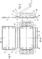
- the housing for electrical or electronic components shown in Figures 1-6 is made in a known manner from plastic and consists of a Floor 1, consisting of four side walls 2, 3, 4 and 5 and a cover 6.
- the bottom 1 is articulated with the side walls 2, 3, 4 and 5 via film hinges 7 connected.
- the design or formation of such film hinges 7 during manufacture of plastic parts is well known to the person skilled in the art, so that here further explanations of these film hinges 7 can be dispensed with.
- the base 1 and the cover 6 can be folded out practically in a common plane, that The same applies to the side walls 2, 3, 4 and 5.
- the side walls 2, 3, 4 and 5 are through in the respective corner area of the housing Locking means releasably connected to each other, the locking means in the illustrated embodiment in each case from mutually corresponding locking webs 8 on the one hand and locking grooves 9 on the other hand.
- the cover 6 is, as already mentioned, with one of the side walls via a film hinge 7 articulated.
- This side wall carries in the illustrated embodiment the reference number 4.
- the cover 6 is in the illustrated embodiment in the area of the upper, circumferential Front edges of the other side walls 2, 3 and 5 with these also through Locking means releasably connected, the locking means again from each other Corresponding locking webs 8 on the one hand and locking grooves 9 on the other hand.
- the locking grooves 9 are in the cover 6 and in locking webs 8 on the upper end edges said side walls 2, 3 and 5 attached.
- FIGS. 1-6 Furthermore, it can be seen from FIGS. 1-6 that the side walls 3 and 5 are joined by the recesses 12 are provided on the respective inside, these being Indentations 12 in the area of the respective outer side by a piece with the Side wall otherwise closure flap 14 connected by predetermined breaking points 13 are limited. The last said is particularly clear from the partial sectional view according to FIG. 3.
- a corresponding construction with depressions 12 can also be provided in the area of the bottom 1 or the cover 6, as shown in FIG. 4 in particular vividly shows.
- the corresponding depressions 12 in Area of the outside of the bottom 1 or the lid 6 by integrally molded and connected to the bottom 1 or the lid 6 by predetermined breaking points 13 Flaps 14 limited.
- locking means are preferably used in the form of mutually corresponding ones Locking bars 8 on the one hand and locking grooves 9 on the other hand use.
- two opposite side walls for example, the side walls designated by reference numerals 2 and 4 molded and longitudinal grooves 10 having webs 11.
- both the side walls and the bottom 1 or the lid 6 can be equipped with depressions 12, which are only by Closure flaps 14 held over predetermined breaking points 13 are closed, such as this has already been described in detail in the exemplary embodiment according to FIGS. 1-6 has been. To that extent, repetitions on these constructive details can be made on this Place to be waived.
Landscapes
- Engineering & Computer Science (AREA)
- Microelectronics & Electronic Packaging (AREA)
- Architecture (AREA)
- Civil Engineering (AREA)
- Structural Engineering (AREA)
- Casings For Electric Apparatus (AREA)
- Compositions Of Macromolecular Compounds (AREA)
- Laminated Bodies (AREA)
- Closures For Containers (AREA)
Abstract
Gegenstand der Erfindung ist ein aus Kunststoff hergestelltes Gehäuse für elektrische oder elektronische Bauteile.
Die Besonderheit des erfindungsgemäßen Gehäuses besteht daß der Boden (1) mit den Seitenwänden (2, 3, 4, 5) und der Deckel (6) mit einer der Seitenwände (4) über Filmscharniere (7) verbunden ist, und daß weiterhin die Seitenwände (2, 3, 4, 5) im jeweiligen Eckbereich des Gehäuses untereinander durch Rastmittel miteinander lösbar verbunden sind und daß der Deckel (6) im Bereich der oberen, umlaufenden Stirnkante der Seitenwände (2, 3, 5) zumindest mit einer dieser Seitenwände (2, 3, 5) ebenfalls durch Rastmittel lösbar verbunden ist.
Durch diese Konstruktion wird ein Gehäuse geschaffen, welches preiswert herstellbar, leicht und ohhe zusätzliche Verschlußmittel montierbar und verschließbar ist und den zusätzlichen Vorteil bietet, daß der Einbau elektrischer oder elektronischer Bauteile in das Gehäuseinnere ohne räumliche Behinerung durch die Seitenwände möglich ist.
Die gleichen Vorteile werden bei einem erfindungsgemäßen Gehäuse erzielt, bei dem die Seitenwände (2, 3, 4, 5) an ihren unteren und oberen Linkskanten durch Rastmitttel lösbar mit dem Boden (1) bzw. dem Deckel (6) und im Eckbereich des Gehäuses untereinander ebenfalls durch Rastmittel lösbar miteinander verbunden sind.
Description
- Figur 1
- eine perspektivische Darstellung eines erfindungsgemäßen Gehäuses im geschlossenen Zustand,
- Figur 2
- eine perspektivische Darstellung des Gehäuses gemäß Figur 1 im geöffneten Zustand,
- Figur 3
- einen Teilschnitt nach der Linie III-III in Figur 2,
- Figur 4
- einen Teilschnitt nach der Linie IV-IV in Figur 3,
- Figur 5
- eine Draufsicht auf das vollständig aufgeklappte Gehäuse nach den Figuren 1 und 2,
- Figur 6
- einen Schnitt nach der Linie VI-VI in Figur 5, wobei durch gestrichelte Linien die Kontur des aufgerichteten Gehäuses dargestellt ist,
- Figur 7
- eine perspektivische Darstellung nach Art eines Sprengbildes betreffend ein Gehäuse nach einem weiteren Ausführungsbeispiel der Erfindung,
- Figur 8
- einen Teilschnitt nach der Linie VIII-VIII in Figur 7,
- Figur 9
- einen Teilschnitt nach der Linie IX-IX in Figur 7.
Claims (6)
- Aus Kunststoff hergestelltes Gehäuse für elektrische oder elektronische Bauteile, bestehend aus einem Boden, aus Seitenwänden und einem Deckel, dadurch gekennzeichnet, daß der Boden (1) mit den Seitenwänden (2, 3, 4, 5) und der Deckel (6) mit einer der Seitenwände (4) über Filmscharniere (7) verbunden ist, daß die Seitenwände (2, 3, 4, 5) im jeweiligen Eckbereich des Gehäuses untereinander durch Rastmittel miteinander lösbar verbunden sind und daß der Deckel (6) im Bereich der oberen, umlaufenden Stirnkante der Seitenwände (2, 3, 5) zumindest mit einer dieser Seitenwände (2, 3, 5) ebenfalls durch Rastmittel lösbar verbunden ist.
- Aus Kunststoff hergestelltes Gehäuse für elektrische oder elektronische Bauteile, bestehend aus einem Boden, aus Seitenwänden und einem Deckel, dadurch gekennzeichnet, daß die Seitenwände (2, 3, 4, 5) an ihren unteren und oberen Längskanten durch Rastmittel lösbar mit dem Boden (1) bzw. dem Deckel (6) und im Eckbereich des Gehäuses untereinander ebenfalls durch Rastmittel lösbar miteinander verbunden sind.
- Gehäuse nach Anspruch 1 oder 2, dadurch gekennzeichnet, daß die Rastmittel jeweils aus miteinander korrespondierenden Raststegen (8) und Rastnuten (9) bestehen.
- Gehäuse nach einem oder mehreren der vorhergehenden Ansprüche, dadurch gekennzeichnet, daß zumindest im Bereich der Verbindungsebene zwischen dem Deckel (6) und den Seitenwänden (2, 3, 4, 5) eine Einstecköffnung (15) für ein einfaches Öffnungswerkzeug wie z. B. einen Schraubendreher (16), vorgesehen ist.
- Gehäuse nach einem oder mehreren der vorhergehenden Ansprüche, dadurch gekennzeichnet, daß zumindest eine Seitenwand (2, 3, 4, 5) und/oder der Boden (1) bzw. der Deckel (6) mit zumindest einer von der Innenseite ausgehenden Einsenkung (12) versehen ist, die im Bereich der jeweiligen Außenseite durch eine einstückig mit der Seitenwand oder dem Boden bzw. dem Deckel durch Sollbruchstellen (13) verbundene Verschlußklappe (14) begrenzt ist.
- Gehäuse nach einem oder mehreren der vorhergehenden Ansprüche, dadurch gekennzeichnet, daß an den Innenseiten zweier gegenüberliegender Seitenwände (2, 4) mindestens jeweils ein mit einer Längsnut (10) versehener und parallel zum Boden (1) bzw. zum Deckel (6) verlaufender Steg (11) angeformt ist, wobei die beiden einander gegenüberliegenden Stege (11) in einem gleichen Abstand zum Boden (1) oder zum Deckel (6) angeordnet sind.
Applications Claiming Priority (2)
| Application Number | Priority Date | Filing Date | Title |
|---|---|---|---|
| DE29720510U | 1997-11-19 | ||
| DE29720510U DE29720510U1 (de) | 1997-11-19 | 1997-11-19 | Aus Kunststoff hergestelltes Gehäuse für elektrische oder elektronische Bauteile |
Publications (3)
| Publication Number | Publication Date |
|---|---|
| EP0918450A2 true EP0918450A2 (de) | 1999-05-26 |
| EP0918450A3 EP0918450A3 (de) | 1999-12-22 |
| EP0918450B1 EP0918450B1 (de) | 2004-12-15 |
Family
ID=8048830
Family Applications (1)
| Application Number | Title | Priority Date | Filing Date |
|---|---|---|---|
| EP98120452A Expired - Lifetime EP0918450B1 (de) | 1997-11-19 | 1998-10-29 | Aus Kunststoff hergestelltes Gehäuse für elektrische oder elektronische Bauteile |
Country Status (4)
| Country | Link |
|---|---|
| EP (1) | EP0918450B1 (de) |
| AT (1) | ATE285167T1 (de) |
| DE (2) | DE29720510U1 (de) |
| DK (1) | DK0918450T3 (de) |
Cited By (4)
| Publication number | Priority date | Publication date | Assignee | Title |
|---|---|---|---|---|
| FR2841090A1 (fr) * | 2002-06-12 | 2003-12-19 | Siemens Ag | Boitier pour appareil electrique, notamment pour vehicule au tomobile |
| DE10334629B3 (de) * | 2003-07-29 | 2005-04-07 | Siemens Ag | Schaltungsmodul und Verfahren zu dessen Herstellung |
| EP1569182A1 (de) * | 2004-02-26 | 2005-08-31 | Robert Bosch GmbH | Detektion von unbefugten Manipulation für ein Sicherheitssystem |
| EP1659554A1 (de) * | 2004-11-18 | 2006-05-24 | Samsung SDI Co., Ltd. | Flachanzeigetafelstützvorrichtung und Flachanzeigetafelvorrichtung mit der Stütze |
Families Citing this family (4)
| Publication number | Priority date | Publication date | Assignee | Title |
|---|---|---|---|---|
| ITBO20030082U1 (it) * | 2003-07-21 | 2005-01-22 | Eur Ex S R L | "cassetta d'ispezione in materia plastica, particolarmente per il cont enimento delle derivazioni delle reti elettriche, del telefono, dell'a cqua o del gas poste a servizio degli edifici, confezionabile con ingom- bro ridotto ed assemblabile dell'ut |
| DE102007010665A1 (de) * | 2007-03-02 | 2008-09-04 | Viessmann Werke Gmbh & Co Kg | Gehäuse |
| US8913395B2 (en) | 2010-02-02 | 2014-12-16 | Apple Inc. | High tolerance connection between elements |
| DE102018110026B4 (de) * | 2018-04-26 | 2022-07-28 | Vega Grieshaber Kg | Elektrogehäuse aus Kunststoff |
Family Cites Families (6)
| Publication number | Priority date | Publication date | Assignee | Title |
|---|---|---|---|---|
| DE2424722C3 (de) * | 1974-05-21 | 1979-12-20 | Siemens Ag, 1000 Berlin Und 8000 Muenchen | Gehäuse für Geräte der elektrischen MeB- und Nachrichtentechnik |
| DE3103534C2 (de) * | 1981-02-03 | 1983-09-08 | Varta Batterie Ag, 3000 Hannover | Batteriegehäuse aus Kunststoff |
| DE8300516U1 (de) * | 1983-01-11 | 1983-04-28 | E. Dold & Söhne KG, 7743 Furtwangen | Gehäuse zur Aufnahme von Bauteilen der Elektromechanik und Elektronik |
| DE8401081U1 (de) * | 1984-01-16 | 1984-04-12 | Siemens AG, 1000 Berlin und 8000 München | Halterung für eine Baugruppe |
| DE3447801A1 (de) * | 1984-12-29 | 1986-07-03 | REHAU AG + Co, 8673 Rehau | Kastenfoermiges bauteil fuer elektrische schalt- und verteileranlagen |
| US5434362A (en) * | 1994-09-06 | 1995-07-18 | Motorola, Inc. | Flexible circuit board assembly and method |
-
1997
- 1997-11-19 DE DE29720510U patent/DE29720510U1/de not_active Expired - Lifetime
-
1998
- 1998-10-29 DK DK98120452T patent/DK0918450T3/da active
- 1998-10-29 EP EP98120452A patent/EP0918450B1/de not_active Expired - Lifetime
- 1998-10-29 DE DE59812381T patent/DE59812381D1/de not_active Expired - Fee Related
- 1998-10-29 AT AT98120452T patent/ATE285167T1/de not_active IP Right Cessation
Cited By (7)
| Publication number | Priority date | Publication date | Assignee | Title |
|---|---|---|---|---|
| FR2841090A1 (fr) * | 2002-06-12 | 2003-12-19 | Siemens Ag | Boitier pour appareil electrique, notamment pour vehicule au tomobile |
| DE10226136B3 (de) * | 2002-06-12 | 2004-01-22 | Siemens Ag | Elektrisches Gerät, insbesondere für ein Kraftfahrzeug |
| DE10334629B3 (de) * | 2003-07-29 | 2005-04-07 | Siemens Ag | Schaltungsmodul und Verfahren zu dessen Herstellung |
| US7090511B2 (en) | 2003-07-29 | 2006-08-15 | Siemens Aktiengesellschaft | Circuit module and method for its manufacture |
| EP1569182A1 (de) * | 2004-02-26 | 2005-08-31 | Robert Bosch GmbH | Detektion von unbefugten Manipulation für ein Sicherheitssystem |
| US7004784B2 (en) | 2004-02-26 | 2006-02-28 | Robert Bosch Gmbh | Tamper detection for security system |
| EP1659554A1 (de) * | 2004-11-18 | 2006-05-24 | Samsung SDI Co., Ltd. | Flachanzeigetafelstützvorrichtung und Flachanzeigetafelvorrichtung mit der Stütze |
Also Published As
| Publication number | Publication date |
|---|---|
| DE29720510U1 (de) | 1999-03-25 |
| DE59812381D1 (de) | 2005-01-20 |
| DK0918450T3 (da) | 2005-03-14 |
| EP0918450A3 (de) | 1999-12-22 |
| ATE285167T1 (de) | 2005-01-15 |
| EP0918450B1 (de) | 2004-12-15 |
Similar Documents
| Publication | Publication Date | Title |
|---|---|---|
| EP0939984B1 (de) | Schaltschrank | |
| DE19817919A1 (de) | Rahmenschenkel für ein Rahmengestell eines Schaltschrankes | |
| EP0939987B1 (de) | Rahmenprofil für ein rahmengestell eines schaltschrankes | |
| EP0918450B1 (de) | Aus Kunststoff hergestelltes Gehäuse für elektrische oder elektronische Bauteile | |
| DE9403833U1 (de) | Öffnungsverschluß | |
| DE4140265A1 (de) | Behaelter fuer eine sauerstoffversorgungseinheit | |
| EP0684185B2 (de) | Faltbarer Verpackungsbehälter | |
| DE2806554C2 (de) | Rolladenkasten | |
| EP0158795A2 (de) | Bedienungsfeld für elektrische und elektronische Geräte | |
| DE19837184C2 (de) | Gestell für einen 19"-Verteilerschrank | |
| EP0910145B1 (de) | Rahmen für einen Kassettendeckel | |
| EP0918451A2 (de) | Gehäuse zur Aufnahme elektrischer oder elektronischer Bauteile | |
| DE69510517T2 (de) | Universelle Kennzeichenschild-Halterung | |
| DE29620192U1 (de) | Bauelementensatz aus zumindest drei gleichen kabusförmigen Behälterelementen | |
| DE3838781A1 (de) | Verpackungskarton | |
| DE4308242C1 (de) | Relais | |
| DE9110413U1 (de) | Behälter, insbesondere Komposter | |
| EP1352456B1 (de) | Gehäuse, insbesondere für den einbau elektrischer und elektronischer bauteile | |
| DE20203792U1 (de) | Rechteckige Vorrichtung zur Aufnahme von Gegenständen, insbesondere Werkstücke | |
| DE29700267U1 (de) | Aus einer Mehrzahl nebeneinanderliegender Ablageplatten bestehende Gepäckablage für Fahrzeuge | |
| DE29601355U1 (de) | Verbindungsknoten für Baukonstruktionen | |
| DE2507620A1 (de) | Kassettenbehaelter | |
| CH653793A5 (de) | Halter fuer nummerntafel. | |
| DE1027066B (de) | Behaelter zur Aufbewahrung von Diapositiven | |
| EP0465492B1 (de) | Teilbarer flaschenkasten |
Legal Events
| Date | Code | Title | Description |
|---|---|---|---|
| PUAI | Public reference made under article 153(3) epc to a published international application that has entered the european phase |
Free format text: ORIGINAL CODE: 0009012 |
|
| AK | Designated contracting states |
Kind code of ref document: A2 Designated state(s): AT DE DK FR IT |
|
| AX | Request for extension of the european patent |
Free format text: AL;LT;LV;MK;RO;SI |
|
| PUAL | Search report despatched |
Free format text: ORIGINAL CODE: 0009013 |
|
| AK | Designated contracting states |
Kind code of ref document: A3 Designated state(s): AT BE CH CY DE DK ES FI FR GB GR IE IT LI LU MC NL PT SE |
|
| AX | Request for extension of the european patent |
Free format text: AL;LT;LV;MK;RO;SI |
|
| RIC1 | Information provided on ipc code assigned before grant |
Free format text: 6H 05K 5/00 A, 6E 05D 1/02 B |
|
| 17P | Request for examination filed |
Effective date: 20000119 |
|
| AKX | Designation fees paid |
Free format text: AT DK FR IT |
|
| RBV | Designated contracting states (corrected) |
Designated state(s): AT DE DK FR IT |
|
| REG | Reference to a national code |
Ref country code: DE Ref legal event code: 8566 |
|
| GRAP | Despatch of communication of intention to grant a patent |
Free format text: ORIGINAL CODE: EPIDOSNIGR1 |
|
| GRAS | Grant fee paid |
Free format text: ORIGINAL CODE: EPIDOSNIGR3 |
|
| GRAA | (expected) grant |
Free format text: ORIGINAL CODE: 0009210 |
|
| RAP1 | Party data changed (applicant data changed or rights of an application transferred) |
Owner name: BERNSTEIN AG |
|
| AK | Designated contracting states |
Kind code of ref document: B1 Designated state(s): AT DE DK FR IT |
|
| REF | Corresponds to: |
Ref document number: 59812381 Country of ref document: DE Date of ref document: 20050120 Kind code of ref document: P Owner name: RACE, EDWARD |
|
| REG | Reference to a national code |
Ref country code: DK Ref legal event code: T3 |
|
| PLBE | No opposition filed within time limit |
Free format text: ORIGINAL CODE: 0009261 |
|
| STAA | Information on the status of an ep patent application or granted ep patent |
Free format text: STATUS: NO OPPOSITION FILED WITHIN TIME LIMIT |
|
| 26N | No opposition filed |
Effective date: 20050916 |
|
| ET | Fr: translation filed | ||
| PGFP | Annual fee paid to national office [announced via postgrant information from national office to epo] |
Ref country code: DK Payment date: 20071023 Year of fee payment: 10 Ref country code: DE Payment date: 20071018 Year of fee payment: 10 |
|
| PGFP | Annual fee paid to national office [announced via postgrant information from national office to epo] |
Ref country code: AT Payment date: 20071024 Year of fee payment: 10 Ref country code: IT Payment date: 20071026 Year of fee payment: 10 |
|
| PGFP | Annual fee paid to national office [announced via postgrant information from national office to epo] |
Ref country code: FR Payment date: 20071019 Year of fee payment: 10 |
|
| REG | Reference to a national code |
Ref country code: DK Ref legal event code: EBP |
|
| REG | Reference to a national code |
Ref country code: FR Ref legal event code: ST Effective date: 20090630 |
|
| PG25 | Lapsed in a contracting state [announced via postgrant information from national office to epo] |
Ref country code: IT Free format text: LAPSE BECAUSE OF NON-PAYMENT OF DUE FEES Effective date: 20081029 Ref country code: DE Free format text: LAPSE BECAUSE OF NON-PAYMENT OF DUE FEES Effective date: 20090501 Ref country code: AT Free format text: LAPSE BECAUSE OF NON-PAYMENT OF DUE FEES Effective date: 20081029 |
|
| PG25 | Lapsed in a contracting state [announced via postgrant information from national office to epo] |
Ref country code: FR Free format text: LAPSE BECAUSE OF NON-PAYMENT OF DUE FEES Effective date: 20081031 Ref country code: DK Free format text: LAPSE BECAUSE OF NON-PAYMENT OF DUE FEES Effective date: 20081031 |