EP0918574B1 - Rohrreinigungsgerät für erdöl- oder gaspipelines - Google Patents
Rohrreinigungsgerät für erdöl- oder gaspipelines Download PDFInfo
- Publication number
- EP0918574B1 EP0918574B1 EP97928390A EP97928390A EP0918574B1 EP 0918574 B1 EP0918574 B1 EP 0918574B1 EP 97928390 A EP97928390 A EP 97928390A EP 97928390 A EP97928390 A EP 97928390A EP 0918574 B1 EP0918574 B1 EP 0918574B1
- Authority
- EP
- European Patent Office
- Prior art keywords
- shield
- cleaning apparatus
- pipe cleaning
- accordance
- pressure
- Prior art date
- Legal status (The legal status is an assumption and is not a legal conclusion. Google has not performed a legal analysis and makes no representation as to the accuracy of the status listed.)
- Expired - Lifetime
Links
- 238000004140 cleaning Methods 0.000 title claims abstract description 104
- 239000007788 liquid Substances 0.000 claims abstract description 89
- 238000007789 sealing Methods 0.000 claims description 6
- 238000012546 transfer Methods 0.000 claims description 5
- 238000003825 pressing Methods 0.000 claims description 4
- 230000009471 action Effects 0.000 claims description 3
- 238000011144 upstream manufacturing Methods 0.000 claims description 2
- 239000010779 crude oil Substances 0.000 claims 1
- 230000002093 peripheral effect Effects 0.000 claims 1
- 238000005096 rolling process Methods 0.000 claims 1
- 230000000630 rising effect Effects 0.000 abstract 1
- 230000008901 benefit Effects 0.000 description 10
- 230000008878 coupling Effects 0.000 description 8
- 238000010168 coupling process Methods 0.000 description 8
- 238000005859 coupling reaction Methods 0.000 description 8
- 238000003860 storage Methods 0.000 description 8
- 230000000694 effects Effects 0.000 description 7
- 239000012530 fluid Substances 0.000 description 7
- 238000005520 cutting process Methods 0.000 description 5
- 230000001419 dependent effect Effects 0.000 description 4
- 238000006073 displacement reaction Methods 0.000 description 4
- 239000002245 particle Substances 0.000 description 4
- 239000006096 absorbing agent Substances 0.000 description 3
- 239000002184 metal Substances 0.000 description 3
- 239000003208 petroleum Substances 0.000 description 3
- 230000035939 shock Effects 0.000 description 3
- 241000282887 Suidae Species 0.000 description 2
- 238000013461 design Methods 0.000 description 2
- 238000010586 diagram Methods 0.000 description 2
- 238000011010 flushing procedure Methods 0.000 description 2
- 230000006870 function Effects 0.000 description 2
- 230000007246 mechanism Effects 0.000 description 2
- 238000005086 pumping Methods 0.000 description 2
- 239000007787 solid Substances 0.000 description 2
- 230000007704 transition Effects 0.000 description 2
- 230000001154 acute effect Effects 0.000 description 1
- 230000009286 beneficial effect Effects 0.000 description 1
- 230000008859 change Effects 0.000 description 1
- 238000006243 chemical reaction Methods 0.000 description 1
- 230000006735 deficit Effects 0.000 description 1
- 238000009826 distribution Methods 0.000 description 1
- 238000007654 immersion Methods 0.000 description 1
- 230000003993 interaction Effects 0.000 description 1
- 238000003754 machining Methods 0.000 description 1
- 238000012423 maintenance Methods 0.000 description 1
- 238000004519 manufacturing process Methods 0.000 description 1
- 239000000463 material Substances 0.000 description 1
- 238000000034 method Methods 0.000 description 1
- 230000008569 process Effects 0.000 description 1
- 238000012545 processing Methods 0.000 description 1
- 239000000047 product Substances 0.000 description 1
- 230000009467 reduction Effects 0.000 description 1
- 230000001105 regulatory effect Effects 0.000 description 1
- 230000007480 spreading Effects 0.000 description 1
- 238000003892 spreading Methods 0.000 description 1
- 239000013589 supplement Substances 0.000 description 1
- 238000012549 training Methods 0.000 description 1
- 230000001960 triggered effect Effects 0.000 description 1
- XLYOFNOQVPJJNP-UHFFFAOYSA-N water Substances O XLYOFNOQVPJJNP-UHFFFAOYSA-N 0.000 description 1
Images





Classifications
-
- B—PERFORMING OPERATIONS; TRANSPORTING
- B08—CLEANING
- B08B—CLEANING IN GENERAL; PREVENTION OF FOULING IN GENERAL
- B08B9/00—Cleaning hollow articles by methods or apparatus specially adapted thereto
- B08B9/02—Cleaning pipes or tubes or systems of pipes or tubes
- B08B9/027—Cleaning the internal surfaces; Removal of blockages
- B08B9/04—Cleaning the internal surfaces; Removal of blockages using cleaning devices introduced into and moved along the pipes
- B08B9/053—Cleaning the internal surfaces; Removal of blockages using cleaning devices introduced into and moved along the pipes moved along the pipes by a fluid, e.g. by fluid pressure or by suction
- B08B9/055—Cleaning the internal surfaces; Removal of blockages using cleaning devices introduced into and moved along the pipes moved along the pipes by a fluid, e.g. by fluid pressure or by suction the cleaning devices conforming to, or being conformable to, substantially the same cross-section of the pipes, e.g. pigs or moles
- B08B9/0553—Cylindrically shaped pigs
-
- B—PERFORMING OPERATIONS; TRANSPORTING
- B08—CLEANING
- B08B—CLEANING IN GENERAL; PREVENTION OF FOULING IN GENERAL
- B08B9/00—Cleaning hollow articles by methods or apparatus specially adapted thereto
- B08B9/02—Cleaning pipes or tubes or systems of pipes or tubes
- B08B9/027—Cleaning the internal surfaces; Removal of blockages
- B08B9/04—Cleaning the internal surfaces; Removal of blockages using cleaning devices introduced into and moved along the pipes
- B08B9/053—Cleaning the internal surfaces; Removal of blockages using cleaning devices introduced into and moved along the pipes moved along the pipes by a fluid, e.g. by fluid pressure or by suction
- B08B9/055—Cleaning the internal surfaces; Removal of blockages using cleaning devices introduced into and moved along the pipes moved along the pipes by a fluid, e.g. by fluid pressure or by suction the cleaning devices conforming to, or being conformable to, substantially the same cross-section of the pipes, e.g. pigs or moles
- B08B9/0551—Control mechanisms therefor
Definitions
- the invention relates to a pipe cleaning device for Petroleum and gas pipelines, the deposits for example have in the form of paraffins, which device with a Liquid flow through the pipeline for cleaning purposes is pushed, the device has a shield.
- a similar facility consists of a Sealing body on which can be rotated in the direction of flow stored cleaning head with nozzles is attached to Solids such as wax from the inner tube wall to remove.
- Solids such as wax from the inner tube wall to remove.
- Braking device attached radially with brake shoes presses against the pipe wall, so the movement from Brake body in the pipe flow to brake and one Build up pressure difference. This pressure difference becomes this used to connect the nozzles via internal by-pass lines to provide a liquid jet and the Set the cleaning head to rotate.
- U.S. patent shows 4,920,600 a Pipe cleaning device from a cleaning head with itself radially, against the flow direction widening scrapers.
- the cleaning head is axial firmly with a support body designed as a pipe plug connected, which has two sealing plates, the each made up of several mutually movable elements consist of pressure surges driven by the flow transferred to the cleaning head.
- the object of the invention is a safe Pipe cleaning device for petroleum or gas pipelines too create.
- This object is achieved with claim 1, by making the shield one or more breakthroughs for one passing liquid flow forms to at a small values with limited feed speed an intended flow resistance one Pressure difference across the shield to form which is sufficient to drive a cleaning device that the deposits in front of the shield and the passing liquid flow passes, the shield is coupled to a braking device that is currently with at least one clamping element adheres to the pipe wall and the clamping element itself determining the feed Transfers braking force to the pipe wall by using the Relative movement between the clamping element and Braking device a secondary fluid over a Throttle point displaced.
- This arrangement ensures that Pipe cleaning device not with raised Feed speeds at which a fixation of the Cleaning head can take place in the axial direction moving forward and that the feed motion is inevitable and autonomous. Doing so Braking energy by throttling to a secondary Liquid flow discharged from the pipe cleaning device heats up and through the device the heat at the passing Liquid flow and the environment passed on.
- Another advantage is that part of the Braking forces with the feed speed like this is coupled that with increasing speed of the Pipe cleaning device in the pipeline also the braking force grows. It is therefore sufficient to stop the flow of liquid Entry of the pipeline with a regulator at constant To regulate liquid flow in order to everywhere along the Pipeline the same conditions for braking on a given feed rate and for that Obtain actuation of the cleaning device.
- the fact that in the shield and cleaning head Breakthroughs for a passing liquid flow can be set at a specific, with a Feed rate coupled braking force one specified pressure difference on the label is observed become.
- the braking force consists of three possible components together: From possible processing staff on Cleaning head in front of the sign, from the sum of the Sliding friction forces between pipe cleaning device and Pipeline against the feed direction and from at least one with a certain feed rate coupled partial braking force. While the Machining forces and the sliding friction forces with their Fluctuations represent disturbance variables, the same as that of Partial braking force dependent on feed rate Fluctuations of the first two according to their Throttle characteristics from, in the pressure force and Feed rate are coupled. The lower the The more constant the disturbance variables are Feed rate. According to at least one throttle characteristics at times achieved in the secondary Liquid flow, can be a partial braking force approximate dependence on the square of the Feed speed can be generated. This disproportionate dependence means that with relative small changes in the feed rate large Differences in partial braking force are generated in order To compensate for disturbances.
- a first option is to use clamping elements as moving rollers pressed radially against the pipe wall execute, which in turn with their rotation one Displacement of the secondary liquid in specified volumes and the resulting secondary liquid flow Brake chokes.
- clamping elements as moving rollers pressed radially against the pipe wall execute, which in turn with their rotation one Displacement of the secondary liquid in specified volumes and the resulting secondary liquid flow Brake chokes.
- a role like using a push crank on hydraulic brake cylinders Throttling points resp. Shock absorbers act, whereby by the Use of multiple roles and multiple Shock absorbers on a roller compensate for the fluctuating force / path characteristics of the individual Thrust crank takes place.
- volumetric pump such as one Vane pump drives whose volume flow over Throttling points is braked.
- Displacement pump designed as a multiple piston pump is.
- the pistons are star-shaped in a first part arranged that rotates with the roller and are during their rotation is guided radially along a wavy line, to each with two check valves from one Low pressure line to suck in secondary liquid and to eject into a high pressure line.
- the roller is pressed over Displacement pump driven with increasing Number of revolutions limited by the throttle High pressure generated, which at the same time on the radial pressing hydraulic piston acts.
- radial Contact forces that are so great that the role does not work the pipe wall slips and the other way around not are great that the braking device over the slide shoe is blocked.
- a braking device with controlled feed rate is gradually two axially offset clamping elements use the radial forces in each Cross-section cancel each other and the stroke of the moment clamping element in the axial direction with a Piston, a secondary, throttled Fluid flow moves to limit while that second, currently not jamming element in a Starting position is moved when changing the Clamping the second element is secondary throttled liquid flow moves. It is useful when changing the clamp overlap the Provide clamping times so that no uncontrolled Sliding can occur. The process then looks like this that at the end of the braked stroke for the first Clamping element comes to a standstill, in which the Clamping the second clamping element in its Starting position is done.
- the nozzles usually also have one with their jet forward directional component to the Keep the sign free of dirt.
- a Distribution of the nozzles on concentric circles for Pipe axis can be uniform and of the angle of rotation independent cut in the deposits on the Pipe wall are generated. It is particularly advantageous if the sign near the pipe wall protrudes Wreath with a variety of nozzles for the detachment of Has residual deposits around the web for the shield cut freely.
- the jet can also have an essential component in the circumferential direction, to be transverse to the feed direction and at an acute angle to the To cut the pipe wall. If the total of the moments Largely impulses from nozzles on shield and cleaning head picks up, the coupling part between the shield and Braking device less stressed on torsion.
- flaps such as a "butterfly" valve can be provided, the Damper wing in the open position only when the flow reverses for example, along with the lifting of the Braking action to be released to a mechanical Block with certainty during the forward movement to exclude.
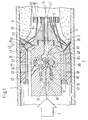
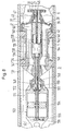
- FIG. 1 With the figures are pipe cleaning devices for petroleum and Gas pipelines are shown holding a sign Cleaning device through a liquid flow in moving the pipeline forward.
- the shield forms in the pipeline one or more breakthroughs for one passing liquid flow to a designated one Build up pressure and is on the back with a Provide braking device, the unwanted large This prevents feed speeds from at least one clamping element currently on the pipe wall sticks and moves relative to the braking device.
- This movement is kinematic on a hydraulic one Displacer transferred to a secondary Liquid flow generated, which over at least one Throttle is braked and so the speed between the shield and the pipe wall.
- FIG 1 is a shield 3 with a Cleaning device 5 shown, for example with Brake devices 8 according to Figures 2 to 7 coupled is what limit its feed rate.
- a pipeline 1 drives a liquid flow 2 Shield 3 in front of it, the outer housing 50 over Packs 42 sealed against the pipeline 1 and is performed at the same time.
- the packs 42 are through a retaining ring 51 secured.
- a gear 56 acts in the inner housing 48 formed hydraulic motor 15 with cams 88 as Pressure booster via a pump system 15 with piston 58 and Check valves 61, 62 on the intake and Pressure lines 59, 60 of a hydraulic auxiliary system, for example for the maintenance of Clamping force used with radial clamping elements 9a, 9b can be.
- An inlet 45 and an outlet 46 are in their cross section coordinated so that the Hydromotor 55 does not exceed at a given pressure difference turn a certain speed in the direction of rotation 57 can.
- An actual cleaning device 5 is in the Shield 3 integrated on its front 4. Concentric to the tube axis 14 is on an arm of the outer housing 50 a baffle 39 attached, the Bores 52 has.
- the baffle 39 has one outer diameter that is smaller than that Inside diameter of expected deposits is 6, and forms - since it protrudes at a distance from the shield 3 - A cavity 40 through the tube wall 1 and not removed deposits 6 is limited.
- Nozzles 36, 37, 38 are provided which are connected via connecting channels 44, an annular channel 43 and pilot holes 49 with Rinsing liquid can be fed under pressure. A part of the nozzles splashes against the pipe wall 1 in order to Feed movement of the shield 3 lumps and chips of Cut away deposits 6.
- the nozzles injects directly or indirectly into the cavity 40 to the detached lumps and chips to a size smash that can pass the baffle 39, and to advance the particles in front of the baffle 39 with the passing and displaced liquid flow 7 to be transported away.
- the low offers Particle size good guarantee that no blockages enter.
- the shield 3 is close the tube wall a ring 41 with nozzles 36, which remove any remaining deposits and the web for cut the packs free.
- annular channel 53 is attached, which has a connection bore 54 with the space in front of the Baffle 39 is connected and that for pressure actuated Switching elements the reference pressure in front of the baffle 39 provides.
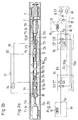
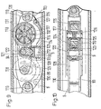
- FIG. 2a The basic arrangement of the elements is shown in FIG. 2a can be seen, the internal piping 65, 66 with an adjustable throttle 21 for braking the secondary Liquid 10 is drawn out in Figure 2b, while Figure 2c shows a hydraulic circuit for the Clamping elements 9a, b shows.
- the first clamping element 9a is clamped in the tube 1 with clamping jaws 11a and brakes over the intermediate braking devices 8a, 8b Shield 3.
- the power flow for the braking force starts from Clamping element 9a via a coupling 77a on the piston rod 27a and piston 13a of the first braking device 8a, wherein secondary liquid 10 from the piston 13a via a Throttle point 21 is displaced and the piston 13b second braking device 8b and an associated one Piston rod 27b and clutch 77c a second Clamping element 9b moved in idle in the feed direction.
- the actual braking movement is from the brake cylinder 12b and from there via tension elements 24 e.g. Wire ropes on the Transfer shield 3.
- tension elements 24 e.g. Wire ropes on the Transfer shield 3.
- tension elements 24 e.g. Wire ropes on the Transfer shield 3.
- tension elements 24 e.g. Wire ropes on the Transfer shield 3.
- tension elements 24 e.g. Wire ropes on the Transfer shield 3.
- tension elements 24 e.g. Wire ropes on the Transfer shield 3.
- tension elements 24 e.g. Wire ropes on the Transfer
- each Guide fins 80 attached to the housing parts hold approximately in the middle of the pipe. Leakage losses from the secondary liquid 10 can by a traveling Pressure accumulator 64 are balanced. As a result of that Pistons 13a, b and cylinders 12a, b have the same dimensions the pistons reach theirs practically at the same time End positions in such a way that they are closest once lying together and farther the other time apart.
- the shield 3 is in the hydraulic diagram with a Pump system 15 and a pressure relief valve 20 shown.
- Pressure accumulators 63, 68 supplement any Leakage amounts on the high pressure and the Low pressure side.
- Pressure line 60 and suction line 59 go in the form of hydraulic hoses that run parallel to the tension elements 24 are guided from the shield 3 to the second Braking device 8b and further as branches 60a, 59a via the clutch 77b to the first braking device 8a, the structure of which can be seen from FIG. 4.
- On the Braking devices are switching valves S11, S12, respectively as well as S21, S22, which depend on the Piston end positions the clamping on the clamping elements 9a and 9b with an overlap of the clamp no unwanted slip against the pipe wall 1 occurs.
- the second clamping element 9b is now in the axial direction rigidly connected to the piston 13b.
- the shield moves in steps like this, the speed with the throttle 21 can be preset.
- FIG 4 is the spatial arrangement of the components the braking device 8a shown.
- the brake cylinder 12a with floor 22 and intermediate floor 23 forms with a Intermediate piece 16a is a supporting housing for the remaining elements.
- a Coupling 77b with a spherical body 33 and a socket connects the intermediate bodies 16a, 16b of the two Braking devices 8a and 8b.
- the spherical body 33 is so big dimensioned that hydraulic lines 65, 66, 59a, 60a, 158a, 158b can be put through.
- the allowable Axial deflection between pan and spherical body 33 is limited to avoid unnecessary hydraulic hoses Suspend loads.
- the switching valves S11, S12 are attached to the transition to the intermediate floor 23, the Switch valve S11 one end position each until it is reached the next end position.
- the connecting line 75a to the clamping element 9a is first on the Intermediate floor 23 guided and then continues as Hydraulic hose on the end of the piston rod 27a and as a bore in the piston rod 27a to the clutch 77a. To prevent an inadmissible rotation of the piston rod 27a to prevent this, a guide cam 29 on the end face along the intermediate piece 16a become.
- the structure of the second braking device 8b with its Clamping element 9b is analog.
- Clamping elements 9a, 9b are shown in FIGS. 3a, 3b.
- the piston rods of the associated clamping pistons 19 protrude into the middle part 76 and act on a displacement body 18 with inclined surfaces 81.
- sliding blocks 17, which as Clamping jaws 11a, 11b are designed to move to the inclined surfaces 81 and to counter surfaces 82 and protrude through slots 83 through the contour of the central parts 76 out.
- Bottoms form the end of the clamping cylinders 78 34.
- a return spring 79 embedded in the cylinder head 39 causes loosening of the clamp at low pressure and that Retracting the jaws 11a, 11b.
- the clamping element 9b is here on its outside by the tension elements 24th and the supply lines 60, 59 happens.
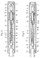
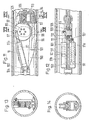
- FIG. 5 Another embodiment of a step by step Braking device is shown in Figures 5, 6 and 7, in which the braking device 8 has only one brake piston 13 with a piston rod 28 running through on both sides has and the displaced secondary liquid 10 over a throttle point 21 on the piston 13 is relaxed.
- the Tension elements 24 (once dashed, once pulled out) are as flexible ropes or straps on the Braking device 8 and attached to the clamping element 9b and in a loop 25 via a deflection roller 26 on the shield 3 guided. This means that the shield 3 only the Half of the relative movement between the housing of the Brake device 8 and the clamping element 9b executes.
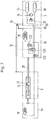
- Figure 7 shows one Hydraulic diagram from which a circuit can be seen, with which the reversal of the clamping takes place.
- a pump 15 In the shield 3 are a pump 15, a pressure relief valve 20 and a High pressure and a low pressure accumulator 63, 68 housed, which via lines 59, 60 with the second clamping element 9b are connected.
- the connection takes place via rollable hydraulic hoses.
- Switch valve S30 engages the end positions of the piston 13 indirectly from the tension element 24, with a switch takes place each time an end position is reached, i.e. an reached end position remains saved until the next is reached.
- the lead to the first Clamping element 9a is in the via a check valve Switching valve S12 guided, which on passage in both Directions will switch as soon as the second Clamping element 9b the high pressure is reached by clamping. So there is again a small overlap in the Clamping.
- the clamping elements 9a, 9b in FIG. 3a and 3b can be used.
- FIG. 8 Another shield 3 with pressure booster 135, Gas storage 95 and cleaning device 5 is shown in FIG. 8 shown.
- the cleaning unit 5 is on the downstream side integrated in the shield 3.
- she consists essentially of nozzles 36, 37, 38 and one the baffle 39 upstream of the nozzles, which for Pipe wall 1 creates a cavity 40 in which the Jet streams for targeted smashing of deposits 6 are easier to keep under control.
- Some nozzles 36, 37 are directed to the deposits 6 on the pipe wall.
- Other nozzles 38 are forward towards the tube axis 14 directed to detached particles in their To suck liquid flow around and around these particles Housing or on the baffle to a size crush, wash away to the front with the passing liquid flow 7 allowed.
- the Baffle grille 39 is also said to detach prematurely Prevent deposits and thus pipe blockages prevent.
- the lattice structure is formed by bores 52 reached.
- a ring 41 near the pipe wall with nozzles 36 prevents residual deposits in the range of sealing packs 42 remain.
- An exterior Housing part 136 carries the sealing to the tube wall 1 Packs 42, which are fixed via retaining rings 142.
- On inner housing 146 is over a front and one rear cover with the outer housing part 136 connected. Exist between the outer and inner housing large passage areas 137, 138 around the nozzles 36, 37, 38 without large pressure drops with liquid supply. Have the pressure difference across the plate 3 pressures of 20 to 30 bar have proven to be sufficient, to dissolve incrustations of paraffins with the nozzles. Higher pressures are possible, keeping an eye on must that the braking devices 8 correspondingly strong must be interpreted.
- a backflow device 141 is installed in the shield 3, the one with reverse flow direction a large one releases additional flow cross-section.
- An over a spring 143 biased piston 141 is inside Housing 146 mounted and gives the reverse Flow direction a passage surface 140 and Muzzle 47 free.
- This room 139 becomes rearward from a commercially available pressure booster 135 limited, the connection 133 for the drive in this Room opens out while a low pressure connection 144 is in shape a connecting pipe 145 with play through the piston 141 through to the mouth area 47 on the baffle 39 protrudes to the pressure booster dispense driving flushing liquid.
- the Pressure booster 135 is a brand Iversen HC2 from Sherex Industries Ltd., 1400 Commerce Parkway, Lancaster, N.Y., USA.
- the pressure booster 135 has a high pressure outlet 134 at which Flushing liquid in a pre-adjustable increased pressure is pending, for example, leakage losses in one Compensate high pressure system during pipe cleaning.
- the pressure acts on you Hydraulic hose 148 and a connecting pipe 157, the locked with a nut 156 on the liquid side 153 of a gas storage 95.
- the gas storage 95 is included a separating piston 154 for liquid 153 and forms a soft, strongly biased spring to Clamping cylinder 93 over an approximately constant pressure, i.e.
- the delivery pressure of the Pressure booster 135 is slightly lower than that specified gas pressure with extended clamping cylinders in order really only in case of leaks in the liquid part liquid reload.
- Clamping cylinder 93 with permanent Clamping effects are shown later in FIGS. 9 and 11 described.
- An outer housing 152 from the gas storage 95 forms the pan with a lid 151 Ball joint 149, which on a retaining ring 150 on Extension 147 of the inner housing 146 is secured.
- the Pressure booster 135 is designed so that Reverse pressure in the backflow in the pressure booster Pilot valve the liquid area 153 with the Connection tube 145 short-circuits.
- a braking device 8 is shown in FIGS. 9 and 10 shown, in which two connected via a bridge 128 Rolls 89 with the bridge 128 radially to the pipe wall be pressed.
- the pressing is done by a Clamping cylinder 93, which is based on a slide shoe 96 supports the opposite side of the pipe with a Clamping piston 94 on a guided in guides 121, 129 Sliding element 123 and further on a pivot axis 122 of the bridge 128 transmitted.
- the clamping cylinder 93 is via a high pressure fluid 112 and a Hydraulic line 114 with a traveling gas storage 95 ( Figure 8) connected, the pressure is set so that with sliding shoe 96 grinding on the pipe wall pressed and at the same time braked rollers 89 die Form clamping elements 9, which at their points of contact adhere to the pipe wall and the feed rate determine.
- An outer housing 130 absorbs the forces Direction of the pipe axis and transfers it via pins 119 and tabs 120 on adjacent links.
- the Slide shoe 96 is a wear part with screws 127 attached to the outer housing.
- Hydraulic line 114 ends with a port 113 for one Hydraulic hose. The clamping force is from the bridge 128 Transfer to the rollers 89 via axes 118.
- the roles 89 are rotatable as axles 115 on the axes 118 stored and form with an anchored on the axis Stator 117, which carries wing 116, one volumetric pump.
- a braking force by the characteristics of the Throttle points 131 is determined.
- Shaft seals 126 seal the bearings 125 of the rollers towards the outside.
- the wings 116 are also with lugs guided in a circumferential groove 124.
- That kind of a Braking device 8 has the advantage that it is short and can be assembled into a multi-link chain that, if the links are offset by 90 ° to each other, can also drive through narrower pipe bends.
- the necessary Number of coupled braking elements 8 also depends from the differential pressure across the shield 3, if one certain feed rate not exceeded shall be.
- the clamping force for the rollers 89 may only be so be chosen high so that the sliding shoes 96 shield 3 do not block.
- FIGS. 16, 17, 18 Another arrangement is shown in FIGS. 16, 17, 18 shown.
- the braking device in FIG. 16 is located at the bottom a slide shoe 96 on the pipe wall 1 and is about an axis 122 opposite the housing 130 of FIG Braking device secured in the axial direction.
- On the Slide shoe 96 act connected to the housing 130 Clamping cylinder 93 with its clamping piston 94 and press at the same time the pressure rollers stored in the housing 130 89 on the opposite side to the pipe wall 1.
- the rollers 89 are arranged in pairs and each form with the Radial piston pump housed in a high pressure line Promote 65. Go from the high pressure line 65 Stub lines to the clamping cylinders 93, so that the Clamping piston 94 the delivery pressure of the radial piston pumps 159 are exposed.
- the radial piston pumps delivered amount of liquid is via a throttle 21a relaxed, with its non-linear characteristics Delivery pressure of the pumps and the clamping piston 94 die Contact force determined.
- Connection lines 66 lead the Liquid on the low pressure side behind the throttle 21a back to the suction side of the pumps.
- the fluctuations of the Liquid volume in the clamping cylinders 93 are compensated by pumps 159 and throttle 21a and the corresponding deficit or the surplus the low pressure side via a connecting line 169 compensated by a liquid reservoir (Fig. 17).
- the hydraulic lines are schematic in Fig. 16 pulled out to better the inner piping detect.
- the liquid reservoir 164 is in one Outer housing 170 arranged, which over a Cover 167 and pins 119 on the braking device (Fig. 16) supports and which is on the other side a cover 172 and a ball joint on the shield (Fig. 18) supports.
- Hydraulic fluid reservoir 153 consists of a piston that over in both directions a piston rod 160, 160a connected to the housing and from a movable cylinder 164, the via a spring 161 in the direction of the piston 163 is pressed.
- the included hydraulic Liquid 153 therefore always experiences a pressure component that is determined by the current spring force.
- Another piston 165 rides on the piston rod 160a, which seals against the outer housing 170 and one Pressure chamber 171 forms.
- This pressure chamber 171 is over a Connection line 174 to the room in front of the sign 3 in close to the baffle 39 connected.
- the piston 165 on the cover 172 is present.
- the piston 165 moves mechanically against the Cylinder 164 on, compensates the biasing force of the spring 161 and lowers the pressure on the low pressure side.
- the Clamping pistons 94 give in and out under external forces excess liquid flows to the storage. At the same time, the rollers 89 lose their engagement and it is no longer pumped.
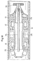
- the shield 3 in Fig. 18 has two packs 42 for Seal pipe wall 1.
- An outer housing 173, 175 is closed on the front by a cover 176, of having a bearing 202 for a rotatable ring 41 Forms cleaning nozzles. When the moments come from the impulses at the cleaning nozzles are not balanced, a Rotation from the ring 41 are generated.
- the lid is 176 continued towards the front by a fastening arm 201, which carries a baffle 39.
- the connecting line 174 leads through the entire shield to the baffle 39.
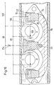
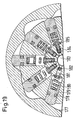
- FIG. 19 shows a radial piston pump with a running body 177, which is connected to the roller 89 (Fig. 16) and the has a wavy inner contour.
- a standing Inner part which with the outer housing 130 (Fig. 16) are connected are radial radial pistons 179 arranged that the inner contour of the rotating barrel 177 follow.
- the pistons 179 with seal 178 run each in bores and are followed by springs 180 pressed outside.
- the piston 179 is lifted over a check valve 182 liquid from a Inlet line 183 sucked in when lowering the Piston via a further check valve 181 in a High pressure line is ejected.
- spherical Closing body supported by a spring 184 that on a holding disc 185 rests.
- the inner housing 176 is on the front pack 42 through an extended lid 176 continued to one in the space obtained with the supporting body 195 rotating in the ring 41 therein accommodate.
- the warehouse 202 is correspondingly longer Support body 195 are elastically supported Guide rollers in front of the longitudinal axis of the tube 1 have a slight inclination and so under pressure on one Coil run off in the tube to create a ring 41 to give predetermined rotation.
- the one with the wreath rotating cleaning nozzles cut into the deposits helical in the pipeline, with additional radial cuts are generated for non-rotating nozzles can, the Rohmbeniform body in the deposits cut out and peel off.
- Prerequisite for a good one Cleaning is that the dwell time of the jet what is possible with the braking device is as constant as possible is achieved.
- FIGS. 22 and 23 It can be seen from FIGS. 22 and 23 that the Rollers 194 with a pin 196 in a cylindrical Carrier body 199 are stored.
- the carrier body 199 is Slidable in a bore with guide grooves 197 and secured against rotation.
- a preloaded pressure spring 200 presses carrier body 199 and guide roller 194 outside to the pipe wall 1.
- the disengagement of the roller 194 is limited by locking jaws 198.
- the slant 203 the running direction of the roller 194 to the longitudinal axis of the Pipeline can be varied by several Guide grooves 197 for a counter shoulder on the support body 199 are provided, or that carrier body 199 with different to the running direction of the roller 194 oriented counter shoulders to choose from.
- a movable friction shoe 189 is shown, the with forward movement 192 on stops 187 from Carrier body 191 rests.
- the friction shoe 189 is over Swivel arms 190 and bearings 188 with the support body 191 connected and forms a parallelogram.
- the attacks 187 are the highest in the axial direction radial deflections (break points) set back somewhat, thus under the radial pressure of clamping pistons 94 Certainly not buckling when driving forward he follows.
- the Friction shoe 189 has a frictional force which is dependent on the pressure in depends on the clamping cylinders 93 and which via an axis 122 transferred from the support body 191 to the outer housing 186 becomes.
- FIGS. 11, 12, 13, 14 Brake device 8 Another one is shown in FIGS. 11, 12, 13, 14 Brake device 8 described. It prevents you uncontrolled feed of the cleaning device 5, by the rotation of the rollers 89 by a Clamping cylinders 93 are pressed against the inner tube wall 1, a thrust crank drive is driven, which consists of two 90 ° offset hydraulic brake cylinders 91a, 91b, the piston rods 97 directly offset by 90 ° to the Roller 89 are connected by means of attachment 109.
- the Thrust crank drive which by means of the piston 90 a drives secondary liquid 10 through throttling points 92, and in each case at the dead center of the first cylinder 91a the greatest volume flow and the greatest braking effect reached with the second cylinder 91b.
- the double roller 89 is supported in a slide bearing 108, whose bearing bush 111 is pressed into two supporting bodies is. These two support bodies can be swiveled on both sides via a common axis 102 on a support body 100 attached the one in the area of the sleeve 111 has slot-shaped recess 99.
- a clamping cylinder 93 creates the necessary by a liquid 112 Contact pressure, which continues into a piston 94 Cone 105 and thus into two pivotable support bodies 101 is initiated and the bushing 111 with bearing 108 the double roller 89 screwed with screws 110 against presses the inner tube wall 1.
- the contact pressure of the The corresponding reaction force is transferred via a common axis 102 and that in the support body 100 built-in clamping cylinder 93 in a opposite of the role initiated sliding shoe 96 with recess 98, the one with the appropriate normal force against the Inner tube wall is pressed, which is caused by the axial Expansion of the slide shoe with the pressed roller together leads to a three-point support that tilts the entire unit from the pipe axis prevented and also by the additional sliding friction allows smaller dimensions of the thrust crank unit.
- This braking device 8 can increase the Cleaning necessary nozzle pressure using articulated elements 104, which are fastened with axes 106, with others same braking device elements 8 are connected, what with higher pumping power for cleaning used liquid flow at the same Feed speed with increased cleaning pressure in the nozzles 36, 37, 38 leads from the shield 3.
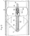
- a reversing plate 103 is described in FIG with a label 3 as described in FIG. 8, can work together.
- the flow reverses, the Flow resistance on the shield 3 by a Backflow device 141 reduced.
- a reversing sign 103 at the other end have the relaxed braking devices 8 and the Withdraws shield 3.
- the Reversing plate 103 therefore consists of a carrier plate 69, which is arranged centrally with play in tube 1 and through lateral guide fins 80 in this middle is held.
- the support plate 69 is a Hinge pin 72 connected to the two flap wings 73a are mounted like a butterfly valve, whereby the elliptical flap wings, however, only one Reach acute-angled extension position 71 to the pipe axis can, in which the pipe cross section largely is closed.
- the biggest game to the pipe wall is in the area of the ends of the hinge pin 72, while the Ends of the flap wing over obstacles such as weld seams can slide away.
- the pressure on the flap wings 73a stands, minus the friction of the flap wings on the Pipe wall, available as traction.
Landscapes
- Physics & Mathematics (AREA)
- Fluid Mechanics (AREA)
- Engineering & Computer Science (AREA)
- Mechanical Engineering (AREA)
- Cleaning In General (AREA)
Abstract
Description
- Fig. 1
- Schematisch einen Schild mit Reinigungskopf, welcher für unterschiedliche Bremseinrichtungen verwendbar ist, wobei im Schild zusätzlich ein Hydromotor als Antrieb für Stellglieder im Reinigungsgerät vorgesehen ist;
- Fig. 2a
- schematisch ein Rohrreinigungsgerät mit einer Bremseinrichtung, die einen schrittweise kontrollierten Vorschub von einem Reinigungskopf gestattet;
- Fig. 2b
- schematisch eine interne Verrohrung für einen in Fig. 2a verwendeten sekundären Flüssigkeitsstrom;
- Fig. 2c
- schematisch eine hydraulische Schaltung für das Zusammenwirken von Klemmelementen und Bremskolben in Fig. 2a, b.
- Fig. 3a, b
- schematisch eine Ausführung für Klemmelemente gemäss Fig. 2a;
- Fig. 4
- schematisch Teile einer Bremseinrichtung gemäss Fig. 2a;
- Fig. 5, 6
- schematisch ein Rohrreinigungsgerät mit einer Bremseinrichtung, die über eine Umlenkrolle mit dem Schild verbunden ist und die über einen einzigen, doppelt wirkenden Kolben einen schrittweise kontrollierten Vorschub gestattet.
- Fig. 7
- schematisch eine hydraulische Schaltung für Klemmelemente gemäss Fig. 5 und 6;
- Fig. 8
- schematisch einen Schild mit Reinigungskopf, welche für unterschiedliche Bremseinrichtungen verwendbar sind, wobei am Schild ein Druckspeicher für hydraulische Klemmeinrichtungen anschliesst und im Schild ein Hydromotor zum Ausgleichen von Leckverlusten an Klemmeinrichtungen eingebaut ist;
- Fig. 9, 10
- schematisch um 90° versetzte Längsschnitte durch eine Bremseinrichtung mit mitlaufenden Rollen, welche die Vorschubgeschwindigkeit bestimmten, indem sie eine gedrosselte volumetrische Pumpe antreiben;
- Fig. 11, 12
- schematisch um 90° versetzte Längsschnitte, durch eine Bremseinrichtung mit mitlaufender Rolle, welche die Vorschubgeschwindigkeit bestimmt, indem sie in der Art eines Kurbeltriebes von zwei um 90° versetzten Stossdämpfern gebremst ist;
- Fig. 13
- schematisch einen Querschnitt durch die Rolle in Fig. 11;
- Fig. 14
- schematisch einen Querschnitt durch einen Klemmzylinder in Fig. 11;
- Fig. 15
- schematisch einen ausklappbaren Rückwärtsschild, um ein Reinigungsgerät bei umgekehrter Strömungsrichtung zurückzuziehen;
- Fig. 16, 17, 18
- schematisch einen Längsschnitt durch ein Rohrreinigungsgerät mit einer Bremseinrichtung, die einen Gleitschuh und Anpressrollen besitzt, mit einem Mittelstück, das einen Speicher für Hydraulikflüssigkeit besitzt, und mit einem Schild, der einen drehbaren Kranz mit Reinigungsdüsen besitzt;
- Fig. 19
- schematisch einen vergrösserten Ausschnitt einer Radialkolbenpumpe aus Fig. 16;
- Fig. 20
- schematisch einen vergrösserten Ausschnitt für einen an Schwenkarmen gelagerten Reibschuh, der beim Rückwärtsfahren aufgrund der Wandreibung zwangsläufig einklappt;
- Fig. 21
- schematisch eine Variante zu Fig. 18, bei der der drehbare Kranz in seiner Drehbewegung über elastisch abgestützte Rollen geführt ist;
- Fig. 22
- schematisch einen vergrösserten Ausschnitt aus Fig. 21 mit einer solchen Führungsrolle; und
- Fig. 23
- schematisch eine Draufsicht auf eine Führungsrolle aus Fig. 22.
- Schaltventil S12 steht auf Durchlass über Rückschlagventil, weil das zweite Klemmelement 9b auf Niederdruck ist.
- Schaltventil S11 gibt den Hochdruck von Druckleitung
60a weiter.
⇒ Klemmbacken 11a sind unter Druck ausgefahren. - Schaltventil S22 steht auf Durchlass in beiden Richtungen, weil das erste Klemmelement 9a auf Hochdruck ist.
- Schaltventil S21 gibt den Niederdruck von
Ansaugleitung 59a weiter
⇒ Klemmbacken 11b sind eingefahren.
- Schaltventil S11 wird auf Niederdruck umgesteuert, der jedoch noch nicht weitergegeben werden kann, da der Druck zum Umsteuern von S12 fehlt. Klemmelement 9a bleibt noch geklemmt.
- Schaltventil S21 wird auf Hochdruck umgesteuert und
kann unabhängig von der Stellung vom Schaltelement S22
den Hochdruck an das Klemmelement 9b weitergeben.
⇒ Klemmbacken 11b werden ausgefahren und es baut sich Hochdruck beim Festsetzen der Klemmbacken auf, welcher nun das Schaltventil S12 auf Durchgang in beiden Richtungen schaltet.
⇒ Klemmbacken 11a werden eingefahren.
Claims (23)
- Rohrreinigungsgerät für Erdöl- und Gaspipelines (1), die Ablagerungen (6) beispielsweise in Form von Paraffinen aufweisen, welches Gerät mit einem Flüssigkeitsstrom (2) zu Reinigungszwecken durch die Pipeline (1) geschoben wird, wobei das Gerät einen Schild (3) aufweist, welcher einen oder mehrere Durchbrüche für einen passierenden Flüssigkeitsstrom (7) bildet, um bei einer auf kleine Werte beschränkten Vorschubgeschwindigkeit mit einem vorgesehenen Strömungswiderstand einen Druckunterschied über den Schild zu bilden, welcher ausreicht um eine Reinigungseinrichtung anzutreiben, die die Ablagerungen vor dem Schild loslöst und dem passierenden Flüssigkeitsstrom übergibt, wobei der Schild (3) an eine Bremseinrichtung (8) gekoppelt ist, die momentan mit mindestens einem Klemmelement (9, 9a, 9b) an der Rohrwand haftet und wobei das Klemmelement selbst die vorschubbestimmende Bremskraft auf die Rohrwand überträgt, indem es mit der Relativbewegung zwischen Klemmelement und Bremseinrichtung eine sekundäre Flüssigkeit über eine Drosselstelle (21, 92, 131) verdrängt.
- Rohrreinigungsgerät nach Anspruch 1, dadurch gekennzeichnet, dass das Klemmelement (9, 9a, 9b) mindestens eine in der Bremseinrichtung (8) gelagerte und radial an die Rohrwand angepresste Rolle (89) aufweist, mit deren Drehung die sekundäre Flüssigkeit (10) verdrängbar ist.
- Rohrreinigungsgerät nach Anspruch 2, dadurch gekennzeichnet, dass mit der der Drehung der Rolle (89) mindestens ein Hydraulikzylinder (91a, 91b) wie bei einer Schubkurbel bewegbar ist, um sekundäre Flüssigkeit (10) zwischen Kolben (90) und Zylinder (91a) zu verdrängen und mit Drosselstellen (92) zu bremsen.
- Rohrreinigungsgerät nach Anspruch 3, dadurch gekennzeichnet, dass an der Rolle (89) ein zweiter um 90° versetzter Hydraulikzylinder (91b) wie mit einer Schubkurbel bewegt wird und sekundäre Flüssigkeit (10) durch Drosselstellen (92) treibt, um jeweils im Totpunkt des ersten Zylinders (91a) den grössten Volumenstrom und die grösste Bremswirkung mit dem zweiten Zylinder (91b) zu erreichen.
- Rohrreinigungsgerät nach Anspruch 2, dadurch gekennzeichnet, dass mit der Bewegung der Rolle (89) eine volumetrische Pumpe (115, 116, 117, 118) antreibbar ist, deren Förderstrom durch eine oder mehrere Drosselstellen (131) gebremst wird.
- Rohrreinigungsgerät nach einem der Ansprüche 2 bis 5, dadurch gekennzeichnet, dass gegenüber einer Rolle (89) ein mit der Bremseinrichtung (8) verbundener Gleitschuh (96) angeordnet ist, um mit einer der Anpresskraft der Rolle entsprechenden Normalkraft am Gleitschuh eine Gleitreibungskraft zur Rohrwand (1) zu erzeugen und so die Bremseinrichtung an der Rolle (89) entsprechend kleiner dimensionieren zu können.
- Rohrreinigungsgerät nach einem der Ansprüche 2 bis 6, dadurch gekennzeichnet, dass die Rolle (90) relativ zur Bremseinrichtung (8) über einen Hochdruckzylinder (93) vorgespannt ist, dessen Kolben (94) dem Druck eines mitfahrenden Druckspeichers (95) ausgesetzt ist.
- Rohrreinigungsgerät nach einem der Ansprüche 2 bis 6, dadurch gekennzeichnet, dass es der Druck der sekundären Flüssigkeit (112) vor der Drosselstelle (21a) ist, der auf einen Hochdruckzylinder (93) mit Kolben (94) wirkt, welche die Rolle (89) relativ zur Bremseinrichtung gegen die Wand (1) der Pipeline vorspannen.
- Rohrreinigungsgerät nach Anspruch 8, dadurch gekennzeichnet, dass ein mitfahrender Speicher (164) für sekundäre Flüssigkeit (153) auf der Niederdruckseite hinter der Drossel (21a) angeschlossen ist, um Leckage von sekundärer Flüssigkeit auszugleichen und um den Niederdruck (66) hinter der Drosselstelle zu bestimmen.
- Rohrreinigungsgerät nach Anspruch 9, dadurch gekennzeichnet, dass der Speicher (164) über eine Federkraft einen Mindestdruck erfährt und dass eine zweite Kraft auf den Speicher wirkt, die proportional zum Druckunterschied über das Rohrreinigungsgerät in der Pipeline ist.
- Rohrreinigungsgerät nach Anspruch 10, dadurch gekennzeichnet, dass beim Rückwärtsfahren durch einen Druckunterschied in umgekehrter Richtung der Druck im Speicher (164) der sekundären Flüssigkeit (153) soweit abbaubar ist, dass beim Rückwärtsfahren keine radiale Anpresskraft mehr besteht.
- Rohrreinigungsgerät nach Anspruch 6, dadurch gekennzeichnet, dass der Gleitschuh (96) zwangsweise beim Rückwärtsfahren einen kleineren radialen Abstand zur Bremseinrichtung einnimmt als beim Vorwärtsfahren.
- Rohrreinigungsgerät nach Anspruch 1, dadurch gekennzeichnet, dass die Bremseinrichtung (8, 8a, 8b) mindestens zwei axial versetzte Klemmelemente (9a, 9b) aufweist, die radial ausfahrbare Klemmbacken (11a, 11b) besitzen und die über einen Bremszylinder und -kolben (12a, 12b, 13a, 13b) axial beweglich miteinander verbunden sind, um durch Drosseln der verdrängten Flüssigkeit eine schrittweise gebremste Bewegung des Schildes (3) zuzulassen.
- Rohrreinigungsgerät nach Anspruch 1, dadurch gekennzeichnet, dass im Schild (3) ein Hydromotor (55, 135) im passierenden Flüssigkeitsstrom (7) eingebaut ist, um damit eine Flüssigkeitspumpe (58) für Hilfsbewegungen am Rohrreinigungsgerät anzutreiben.
- Rohrreinigungsgerät nach einem der Ansprüche 1 bis 14, dadurch gekennzeichnet, dass der Schild (3) auf seiner Vorderseite (4) eine Vielzahl von Düsen (36, 37, 38) aufweist, welche mit zueinander versetzten Flüssigkeitsstrahlen die Ablagerungen (6) in Stücke schneiden.
- Rohrreinigungsgerät nach Anspruch 15, dadurch gekennzeichnet, dass der Schild (3) auf der Vorderseite vor den Düsen (36, 37, 38) ein Prallgitter (39) aufweist, welches nur einen Bruchteil des Rohrquerschnitts ausfüllt, um nicht in den Ablagerungen stecken zu bleiben, welches jedoch den Düsen (36, 37, 38) soweit vorgelagert ist, dass ein Hohlraum (40) für die Verwirbelung von losgeschnittenen Stücken entsteht, um die umhergewirbelten Stücke mit Hilfe des Prallgitters (39) zu zerschlagen und dem passierenden Flüssigkeitsstrom (7) beizumischen.
- Rohrreinigungsgerät nach Anspruch 16, dadurch gekennzeichnet, dass Düsen (37, 38) jeweils als Gruppen auf zueinander konzentrischen Kreisen verteilt sind und in ihrer Strahlrichtung mindestens eine zur Rohrachse parallele und nach vorne weisende Richtungskomponente aufweisen, um vor dem Eintreffen des Schildes die Verschmutzungen abzuführen.
- Rohrreinigungsgerät nach Anspruch 17, dadurch gekennzeichnet, dass sich die Impulse von den Düsen auf den Reinigungskopf am Schild (3) in Umfangsrichtung als Momentensumme weitgehend aufheben.
- Rohrreinigungsgerät nach einem der Ansprüche 15 bis 18, dadurch gekennzeichnet, dass der Schild (3) nahe der Rohrwand (1) einen vorstehenden Kranz (41) mit einer Vielzahl von Düsen (36) für die Ablösung von Restablagerungen aufweist, um die Bahn für den Schild (3) frei zu schneiden.
- Rohrreinigungsgerät nach Anspruch 15, dadurch gekennzeichnet, dass die Vorderseite (4, 41) vom Schild (3) relativ zum Dichtungsteil (42) drehbar ist.
- Rohrreinigungsgerät nach Anspruch 20, dadurch gekennzeichnet, dass in der Vorderseite (4) mindestens zwei federnd gelagerte Stützrollen (194) eingebaut sind, die wendelförmig in der Pipeline abrollen und die der Vorderseite (41) durch ihre Abrollbewegung eine Drehung verleihen.
- Rohrreinigungsgerät nach einem der Ansprüche 1 bis 21, dadurch gekennzeichnet, dass der Schild (3) eine Art Rückströmeinrichtung (141) aufweist, die bei umgekehrter Strömung zum Flüssigkeitsstrom (2) zusätzliche Durchtrittsfläche (140) freigibt, und dass das Rohrreinigungsgerät an seiner Rückseite einen zusätzlichen Rückfahrschild (103) aufweist, der bei umgekehrter Strömung einen wesentlich grösseren Strömungswiderstand bildet, um das Rohrreinigungsgerät in umgekehrter Richtung zu bewegen.
- Rohrreinigungsgerät nach einem der Ansprüche 1 bis 21, dadurch gekennzeichnet, dass der Schild (3) durch die Strömungsumkehr einen grösseren Querschnitt im Rohr (1) freigibt und dass durch diese Freigabebewegung die Wirkung der Klemmelemente (9, 9a, 9b) an der Bremseinrichtung (8) aufhebbar ist.
Priority Applications (1)
| Application Number | Priority Date | Filing Date | Title |
|---|---|---|---|
| EP97928390A EP0918574B1 (de) | 1996-07-18 | 1997-07-10 | Rohrreinigungsgerät für erdöl- oder gaspipelines |
Applications Claiming Priority (4)
| Application Number | Priority Date | Filing Date | Title |
|---|---|---|---|
| EP96810471A EP0819480A1 (de) | 1996-07-18 | 1996-07-18 | Rohrreinigungsgerät für Erdöl- oder Gaspipelines |
| EP96810471 | 1996-07-18 | ||
| PCT/IB1997/000858 WO1998003274A1 (de) | 1996-07-18 | 1997-07-10 | Rohrreinigungsgerät für erdöl- oder gaspipelines |
| EP97928390A EP0918574B1 (de) | 1996-07-18 | 1997-07-10 | Rohrreinigungsgerät für erdöl- oder gaspipelines |
Publications (2)
| Publication Number | Publication Date |
|---|---|
| EP0918574A1 EP0918574A1 (de) | 1999-06-02 |
| EP0918574B1 true EP0918574B1 (de) | 2001-08-29 |
Family
ID=8225654
Family Applications (2)
| Application Number | Title | Priority Date | Filing Date |
|---|---|---|---|
| EP96810471A Withdrawn EP0819480A1 (de) | 1996-07-18 | 1996-07-18 | Rohrreinigungsgerät für Erdöl- oder Gaspipelines |
| EP97928390A Expired - Lifetime EP0918574B1 (de) | 1996-07-18 | 1997-07-10 | Rohrreinigungsgerät für erdöl- oder gaspipelines |
Family Applications Before (1)
| Application Number | Title | Priority Date | Filing Date |
|---|---|---|---|
| EP96810471A Withdrawn EP0819480A1 (de) | 1996-07-18 | 1996-07-18 | Rohrreinigungsgerät für Erdöl- oder Gaspipelines |
Country Status (5)
| Country | Link |
|---|---|
| US (1) | US6070285A (de) |
| EP (2) | EP0819480A1 (de) |
| AU (1) | AU3270497A (de) |
| DE (1) | DE59704470D1 (de) |
| WO (1) | WO1998003274A1 (de) |
Families Citing this family (35)
| Publication number | Priority date | Publication date | Assignee | Title |
|---|---|---|---|---|
| FR2767179B1 (fr) * | 1997-08-08 | 1999-09-10 | Coflexip | Systeme multi-outils utilisable pour le raccordement de conduites |
| DE19820290A1 (de) * | 1998-05-07 | 1999-11-11 | Pipetronix Gmbh | Rohrleitungsfahrzeug |
| JP3069558B1 (ja) * | 1999-07-30 | 2000-07-24 | 株式会社日立製作所 | 制御棒案内管清掃装置 |
| US6370721B1 (en) * | 2000-10-03 | 2002-04-16 | Tuboscope I/P, Inc. | Variable speed pig for pipeline applications |
| US6789938B2 (en) * | 2001-08-29 | 2004-09-14 | Conagra Grocery Products Company | Device and method for removing build-up on measurement gauges |
| US6857158B1 (en) | 2003-07-24 | 2005-02-22 | Junius Hunter | Apparatus for cleaning the interior of pipelines |
| US20070151055A1 (en) | 2006-01-04 | 2007-07-05 | 766089 Alberta Ltd. | Pipeline pig brush and brush assembly |
| NO331436B1 (no) * | 2008-01-16 | 2011-12-27 | Aker Well Service As | Anordning ved renseverktoy |
| NO328188B1 (no) * | 2008-03-11 | 2010-01-04 | Qsst As | Anordning og femgangsmåte for fjerning av avleiring i en borehullsinstallasjon |
| US8650694B2 (en) * | 2008-07-03 | 2014-02-18 | Tdw Delaware, Inc | Speed regulated pipeline pig |
| US20100154153A1 (en) * | 2008-12-24 | 2010-06-24 | 766089 Alberta Ltd. | Pipeline pig brush |
| US8052801B2 (en) * | 2009-01-08 | 2011-11-08 | Tdw Delaware, Inc. | Pipeline pig launch pin and retraction system |
| US8479345B2 (en) * | 2009-08-12 | 2013-07-09 | Tdw Delaware, Inc. | Speed control drive section with failsafe valve |
| GB0918992D0 (en) * | 2009-10-30 | 2009-12-16 | Stats Uk Ltd | Pipeline tool |
| US8316500B2 (en) * | 2009-12-14 | 2012-11-27 | Tdw Delaware, Inc. | Bidirectional bristle pig with sliding collar |
| US9534479B2 (en) * | 2011-08-29 | 2017-01-03 | Amec Foster Wheeler Usa Corporation | Method and system for recovering, and displacing fluid from, a pipe |
| CN102343346B (zh) * | 2011-10-28 | 2013-06-05 | 江苏宏丰奥凯机电有限公司 | 高压油管内腔清洗夹具 |
| US9222612B2 (en) * | 2012-01-06 | 2015-12-29 | Vadxx Energy LLC | Anti-fouling apparatus for cleaning deposits in pipes and pipe joints |
| CN104105781A (zh) | 2012-02-09 | 2014-10-15 | 梵德克斯能源有限责任公司 | 用于转化聚合物废物的区域-划定的热解设备 |
| JP2015512972A (ja) | 2012-02-15 | 2015-04-30 | バドックス エナジー エルエルシーVadxx Energy Llc | 2段階分割帯域熱分解装置 |
| US8931558B1 (en) * | 2012-03-22 | 2015-01-13 | Full Flow Technologies, Llc | Flow line cleanout device |
| RU2498049C1 (ru) * | 2012-07-17 | 2013-11-10 | Виктор Егорович Александров | Устройство для очистки внутренней поверхности насосно-компрессорной трубы |
| WO2015020626A1 (en) * | 2012-08-04 | 2015-02-12 | Absolute Oilfield Equipment, LLC | Brake, shear and cable management system and method |
| CN103203347B (zh) * | 2012-12-05 | 2015-03-25 | 中建安装工程有限公司 | 一种水力驱动的弹性运动刷装置 |
| RU2524581C1 (ru) * | 2013-03-22 | 2014-07-27 | Федеральное государственное бюджетное образовательное учреждение высшего профессионального образования "Уфимский государственный нефтяной технический университет" | Устройство для очистки внутренней поверхности труб |
| WO2015050673A1 (en) * | 2013-10-01 | 2015-04-09 | Bp Corporation North America Inc. | Apparatus and methods for clearing a subsea tubular |
| US9375765B1 (en) | 2015-10-09 | 2016-06-28 | Crossford International, Llc | Tube scraper projectile |
| CN105678387A (zh) * | 2016-01-04 | 2016-06-15 | 西南石油大学 | 一种天然气管道跨越结构的清管安全评价方法 |
| DE102016104761A1 (de) * | 2016-03-15 | 2017-09-21 | Rosen Swiss Ag | Molch zum Aufbringen von Flüssigkeit auf die Innenwand einer Rohrleitung |
| US10661363B2 (en) | 2018-04-09 | 2020-05-26 | Absolute Oilfield Equipment, LLC | Cable shearing apparatus and method |
| US11446710B2 (en) * | 2018-12-14 | 2022-09-20 | The Boeing Company | Wash and dry tool for enclosed channels and method for use |
| CN109629661B (zh) * | 2019-01-22 | 2020-12-11 | 绍兴市柯桥政全纺织有限公司 | 一种市政工程用管道智能清洗装置 |
| EP4171889A4 (de) * | 2020-06-30 | 2024-06-12 | Northeast Gas Association | Verbessertes robotisches inline-rohrinspektionssystem und vorrichtung |
| WO2024091530A1 (en) * | 2022-10-26 | 2024-05-02 | Sonny's Hfi Holdings, Llc | Nozzle assembly |
| US12383939B2 (en) | 2023-02-21 | 2025-08-12 | Baranko Environmental LLC | Oilfield tubing cleaning |
Family Cites Families (10)
| Publication number | Priority date | Publication date | Assignee | Title |
|---|---|---|---|---|
| GB567658A (en) * | 1943-06-15 | 1945-02-26 | Glenfield & Kennedy Ltd | An improved device for scraping the walls of pipe lines such as air lines and water mains |
| CA922457A (en) * | 1969-04-10 | 1973-03-13 | D. Powers Marvin | Pipeline pigs |
| EP0001155B1 (de) * | 1977-07-27 | 1981-05-27 | British Gas Corporation | Rohrleitungsinspektionssystem mit einem mit Geschwindigkeitskontrollmitteln versehenen Fahrzeug und ein solches Fahrzeug mit durch Geschwindigkeitsabhängige Mittel betätigten Bremsklötzen |
| SU797804A1 (ru) * | 1979-01-02 | 1981-01-23 | Алма-Атинский Комплексный Отделказахского Научно-Исследовательскогоинститута Водного Хозяйства | Устройство дл очистки внутреннейпОВЕРХНОСТи ТРубОпРОВОдА |
| IT1147249B (it) * | 1981-12-02 | 1986-11-19 | Antonio Rognoni | Dispositivo mobile per il riempimento di condotto con fluidi, per lo svuotamento e l'essicamento delle stesse, e per la separazione di fluidi diversi durante il loro trasporto in condotta |
| SU1368053A1 (ru) * | 1986-07-24 | 1988-01-23 | А. П. Архипов, В. Е. Павленко и В. Н. Лось-(53)621.7.024(088.8) | Устройство дл обнаружени очистного снар да в трубопроводе |
| US4920600A (en) * | 1987-08-13 | 1990-05-01 | Reinhart S. A. | Pipe cleaner |
| JPH05245456A (ja) * | 1992-03-05 | 1993-09-24 | Kyokuto Kaihatsu Kogyo Co Ltd | 管路清掃装置 |
| CA2075089A1 (en) * | 1992-07-31 | 1994-02-01 | Gerald Howard Lawther | Apparatus and method for removing undesired coatings from the interior of tubes |
| US5617604A (en) * | 1994-09-06 | 1997-04-08 | Erich; Richard R. | Pivoted roller cutter pipe cleaning tool |
-
1996
- 1996-07-18 EP EP96810471A patent/EP0819480A1/de not_active Withdrawn
-
1997
- 1997-07-10 EP EP97928390A patent/EP0918574B1/de not_active Expired - Lifetime
- 1997-07-10 WO PCT/IB1997/000858 patent/WO1998003274A1/de not_active Ceased
- 1997-07-10 AU AU32704/97A patent/AU3270497A/en not_active Abandoned
- 1997-07-10 DE DE59704470T patent/DE59704470D1/de not_active Expired - Lifetime
- 1997-07-17 US US08/895,929 patent/US6070285A/en not_active Expired - Lifetime
Also Published As
| Publication number | Publication date |
|---|---|
| AU3270497A (en) | 1998-02-10 |
| WO1998003274A1 (de) | 1998-01-29 |
| DE59704470D1 (de) | 2001-10-04 |
| EP0819480A1 (de) | 1998-01-21 |
| EP0918574A1 (de) | 1999-06-02 |
| US6070285A (en) | 2000-06-06 |
Similar Documents
| Publication | Publication Date | Title |
|---|---|---|
| EP0819480A1 (de) | Rohrreinigungsgerät für Erdöl- oder Gaspipelines | |
| DE69709862T2 (de) | Hydraulische vorrichtung zur integration in einen rohrstrang | |
| DE60107294T2 (de) | Vorrichtung und vefahren zur rohrreinigung durch bürsten | |
| DE3000619A1 (de) | Hebelbetaetigte kupplung fuer druckmittelleitungen | |
| DE2047587A1 (de) | Entkupplungsvorrichtung | |
| WO1986004975A1 (fr) | Dispositif pour mastiquer toutes sortes d'irregularites de surface dans une canalisation inaccessible | |
| DE3312958C2 (de) | ||
| EP2126447A1 (de) | Schnellkupplung für die verbindung von hydraulikleitungen, insbesondere bei erdbewegungsmaschinen sowie deren auswechselbaren ausbaugeräten und werkzeugen | |
| DE1963093B2 (de) | Vorrichtung zum Ausreiben von Rohrleitungen | |
| DE102009054183A1 (de) | Zug- und Druckvorrichtung | |
| DE3237583C2 (de) | Spülkopf | |
| DE19957791A1 (de) | Hydraulischer Bohrantrieb | |
| DE2211167A1 (de) | ||
| DE2134660A1 (de) | Zum durchpumpen durch eine rohrleitung dienendes werkzeug | |
| EP2742202A2 (de) | Spannkette | |
| DE112010003409T5 (de) | Hydraulischer Radialmotor | |
| DE3941953A1 (de) | Vorrichtung zur entkokung und ihre verwendung | |
| DE2652614C3 (de) | Schwenkeinrichtung für das um die Schrämwalzenachse schwenkbar gelagerte Räumblech einer Walzenschrämmaschine | |
| DE4211146A1 (de) | Vorrichtung zur Innenreinigung von Rohren bzw. rohrähnlichen oder langgestreckten Hohlräumen | |
| DE9319684U1 (de) | Fortbewegungsvorrichtung zum Durchfahren von rohrförmigen Kanälen o.dgl. | |
| DE2542005A1 (de) | Kippbares duowalzgeruest | |
| DE2746668B2 (de) | Rohrreinigungsgerät für Wasser-, Gas- und Industrieleitungen | |
| DE3439653C1 (de) | Vorrichtung zum Verbinden eines Bohrstranges mit einem Rohr od.dgl. | |
| DE60024788T2 (de) | Nockenaktiviertes hydraulisches Bremssystem | |
| DE1044641B (de) | Hydraulische Hilfskraftlenkung fuer Kraftfahrzeuge |
Legal Events
| Date | Code | Title | Description |
|---|---|---|---|
| PUAI | Public reference made under article 153(3) epc to a published international application that has entered the european phase |
Free format text: ORIGINAL CODE: 0009012 |
|
| 17P | Request for examination filed |
Effective date: 19981109 |
|
| AK | Designated contracting states |
Kind code of ref document: A1 Designated state(s): CH DE GB LI NL |
|
| GRAG | Despatch of communication of intention to grant |
Free format text: ORIGINAL CODE: EPIDOS AGRA |
|
| 17Q | First examination report despatched |
Effective date: 20000929 |
|
| GRAG | Despatch of communication of intention to grant |
Free format text: ORIGINAL CODE: EPIDOS AGRA |
|
| GRAH | Despatch of communication of intention to grant a patent |
Free format text: ORIGINAL CODE: EPIDOS IGRA |
|
| GRAH | Despatch of communication of intention to grant a patent |
Free format text: ORIGINAL CODE: EPIDOS IGRA |
|
| GRAH | Despatch of communication of intention to grant a patent |
Free format text: ORIGINAL CODE: EPIDOS IGRA |
|
| GRAA | (expected) grant |
Free format text: ORIGINAL CODE: 0009210 |
|
| AK | Designated contracting states |
Kind code of ref document: B1 Designated state(s): CH DE GB LI NL |
|
| REG | Reference to a national code |
Ref country code: CH Ref legal event code: EP |
|
| REF | Corresponds to: |
Ref document number: 59704470 Country of ref document: DE Date of ref document: 20011004 |
|
| GBT | Gb: translation of ep patent filed (gb section 77(6)(a)/1977) |
Effective date: 20011016 |
|
| REG | Reference to a national code |
Ref country code: CH Ref legal event code: NV Representative=s name: SULZER MANAGEMENT AG |
|
| REG | Reference to a national code |
Ref country code: GB Ref legal event code: IF02 |
|
| PLBE | No opposition filed within time limit |
Free format text: ORIGINAL CODE: 0009261 |
|
| STAA | Information on the status of an ep patent application or granted ep patent |
Free format text: STATUS: NO OPPOSITION FILED WITHIN TIME LIMIT |
|
| 26N | No opposition filed | ||
| PGFP | Annual fee paid to national office [announced via postgrant information from national office to epo] |
Ref country code: CH Payment date: 20110725 Year of fee payment: 15 |
|
| PGFP | Annual fee paid to national office [announced via postgrant information from national office to epo] |
Ref country code: GB Payment date: 20120719 Year of fee payment: 16 |
|
| PGFP | Annual fee paid to national office [announced via postgrant information from national office to epo] |
Ref country code: DE Payment date: 20120720 Year of fee payment: 16 |
|
| PGFP | Annual fee paid to national office [announced via postgrant information from national office to epo] |
Ref country code: NL Payment date: 20120719 Year of fee payment: 16 |
|
| REG | Reference to a national code |
Ref country code: NL Ref legal event code: V1 Effective date: 20140201 |
|
| REG | Reference to a national code |
Ref country code: CH Ref legal event code: PL |
|
| GBPC | Gb: european patent ceased through non-payment of renewal fee |
Effective date: 20130710 |
|
| REG | Reference to a national code |
Ref country code: DE Ref legal event code: R119 Ref document number: 59704470 Country of ref document: DE Effective date: 20140201 |
|
| PG25 | Lapsed in a contracting state [announced via postgrant information from national office to epo] |
Ref country code: NL Free format text: LAPSE BECAUSE OF NON-PAYMENT OF DUE FEES Effective date: 20140201 Ref country code: CH Free format text: LAPSE BECAUSE OF NON-PAYMENT OF DUE FEES Effective date: 20130731 Ref country code: DE Free format text: LAPSE BECAUSE OF NON-PAYMENT OF DUE FEES Effective date: 20140201 Ref country code: GB Free format text: LAPSE BECAUSE OF NON-PAYMENT OF DUE FEES Effective date: 20130710 Ref country code: LI Free format text: LAPSE BECAUSE OF NON-PAYMENT OF DUE FEES Effective date: 20130731 |