EP0918948B1 - Kugelgleichlaufdrehgelenk mit optimiertem rollfehler - Google Patents
Kugelgleichlaufdrehgelenk mit optimiertem rollfehler Download PDFInfo
- Publication number
- EP0918948B1 EP0918948B1 EP97935512A EP97935512A EP0918948B1 EP 0918948 B1 EP0918948 B1 EP 0918948B1 EP 97935512 A EP97935512 A EP 97935512A EP 97935512 A EP97935512 A EP 97935512A EP 0918948 B1 EP0918948 B1 EP 0918948B1
- Authority
- EP
- European Patent Office
- Prior art keywords
- joint
- ball
- angle
- balls
- plane
- Prior art date
- Legal status (The legal status is an assumption and is not a legal conclusion. Google has not performed a legal analysis and makes no representation as to the accuracy of the status listed.)
- Expired - Lifetime
Links
Images


Classifications
-
- F—MECHANICAL ENGINEERING; LIGHTING; HEATING; WEAPONS; BLASTING
- F16—ENGINEERING ELEMENTS AND UNITS; GENERAL MEASURES FOR PRODUCING AND MAINTAINING EFFECTIVE FUNCTIONING OF MACHINES OR INSTALLATIONS; THERMAL INSULATION IN GENERAL
- F16D—COUPLINGS FOR TRANSMITTING ROTATION; CLUTCHES; BRAKES
- F16D3/00—Yielding couplings, i.e. with means permitting movement between the connected parts during the drive
- F16D3/16—Universal joints in which flexibility is produced by means of pivots or sliding or rolling connecting parts
- F16D3/20—Universal joints in which flexibility is produced by means of pivots or sliding or rolling connecting parts one coupling part entering a sleeve of the other coupling part and connected thereto by sliding or rolling members
- F16D3/22—Universal joints in which flexibility is produced by means of pivots or sliding or rolling connecting parts one coupling part entering a sleeve of the other coupling part and connected thereto by sliding or rolling members the rolling members being balls, rollers, or the like, guided in grooves or sockets in both coupling parts
- F16D3/223—Universal joints in which flexibility is produced by means of pivots or sliding or rolling connecting parts one coupling part entering a sleeve of the other coupling part and connected thereto by sliding or rolling members the rolling members being balls, rollers, or the like, guided in grooves or sockets in both coupling parts the rolling members being guided in grooves in both coupling parts
- F16D3/2237—Universal joints in which flexibility is produced by means of pivots or sliding or rolling connecting parts one coupling part entering a sleeve of the other coupling part and connected thereto by sliding or rolling members the rolling members being balls, rollers, or the like, guided in grooves or sockets in both coupling parts the rolling members being guided in grooves in both coupling parts where the grooves are composed of radii and adjoining straight lines, i.e. undercut free [UF] type joints
-
- F—MECHANICAL ENGINEERING; LIGHTING; HEATING; WEAPONS; BLASTING
- F16—ENGINEERING ELEMENTS AND UNITS; GENERAL MEASURES FOR PRODUCING AND MAINTAINING EFFECTIVE FUNCTIONING OF MACHINES OR INSTALLATIONS; THERMAL INSULATION IN GENERAL
- F16D—COUPLINGS FOR TRANSMITTING ROTATION; CLUTCHES; BRAKES
- F16D3/00—Yielding couplings, i.e. with means permitting movement between the connected parts during the drive
- F16D3/16—Universal joints in which flexibility is produced by means of pivots or sliding or rolling connecting parts
- F16D3/20—Universal joints in which flexibility is produced by means of pivots or sliding or rolling connecting parts one coupling part entering a sleeve of the other coupling part and connected thereto by sliding or rolling members
- F16D3/22—Universal joints in which flexibility is produced by means of pivots or sliding or rolling connecting parts one coupling part entering a sleeve of the other coupling part and connected thereto by sliding or rolling members the rolling members being balls, rollers, or the like, guided in grooves or sockets in both coupling parts
- F16D3/223—Universal joints in which flexibility is produced by means of pivots or sliding or rolling connecting parts one coupling part entering a sleeve of the other coupling part and connected thereto by sliding or rolling members the rolling members being balls, rollers, or the like, guided in grooves or sockets in both coupling parts the rolling members being guided in grooves in both coupling parts
- F16D2003/2232—Elements arranged in the hollow space between the end of the inner shaft and the outer joint member
Definitions
- the invention relates to a constant velocity ball joint in a fixed joint design with an outer joint part with longitudinally running inside curved outer ball tracks, an inner joint part with the outside longitudinally curved inner ball tracks, a plurality of torque transmitting balls, each in each other associated outer and inner ball tracks are performed, and a ball cage with a plurality of cage windows in which the balls are each recorded, the tangent planes to the balls in those effective in torque transmission Contact points of the balls with the outer and inner ball tracks define a spatial control angle K and where the Superposition of the current local relative speeds in the contact points of the outer and inner Ball tracks and the balls defined the rolling error ⁇ v.
- the instantaneous speed component can be used as the roll error ⁇ v the movement of a center of the sphere are considered with which a ball would leave the cage level, unless it came from Cage would be held back and provided in the ball contact points to the ball tracks of the joint piece (outer joint part) and the Ball hub (inner joint part) no sliding would occur.
- the roll error ⁇ v depends on the respective phase angle ⁇ of the balls with respect to those through the axes of the joint components spanned joint plane.
- the cage must have the balls in the Hold the cage level and the balls slide into the Points of contact with the ball tracks.
- a disadvantage of the known joints is that in the areas there is a considerable rolling error with large support forces is. Large rolling errors, i. H. large sliding components combined with large support forces result in high friction and associated high wear continues to arise but also high internal joint forces that ensure maximum resilience lower the joint, especially the cage.
- the invention is based on the object to provide constant velocity ball joints in a fixed joint design, the reduced frictional forces in flexed operation and thus low wear and higher torque capacity exhibit.
- the center lines of the mutually associated outer and inner ball tracks lie in a radial plane AA when the joint is stretched through the coincident central axes of the outer joint part and the inner joint part and comprise circular arcs whose radius of curvature R 1 is less than the rolling circle radius R. 0 , so that the tracks are designed in such a way that when the joint is bent, minimal control angles K coincide with areas of minimal rolling error ⁇ v.
- the ball constant velocity joint comprises an outer joint part 11, also called a joint piece, an inner joint part 12, also called a ball hub, a ball cage 13 with cage windows 14 and balls held in the cage windows 15.
- the Balls engage in outer ball tracks 21 in the outer joint part and inner ball tracks 22 in the inner joint part.
- the tracks are in View A viewed without an undercut, so that the joint as UF joint (undercutfree) is called.
- the outer spherical surface 23 of the cage is in an inner spherical surface 24 of the outer joint part 11 guided so that the joint is a fixed joint, that pivots around a fixed center of the joint M.
- the inner joint part 12 has a shaft-toothed inner opening 28 for inserting a shaft.
- Phase positions shown starting from the phase angle ⁇ be designated by an assumed joint flexion plane XZ.
- the spherical representations are here without a fixed assignment to each other, d. H. it is not the majority of balls of a joint in its functionally determined by the cage Distance position, but around different phase positions a ball on its approximate circular orbit with the revolving Joint.
- the through the center plane of the ball cage given common spherical plane XZ left through the drawing plane and reproduced on the right perpendicular to the plane of the drawing.
- the other two bow to this plane XZ Joint components - outer joint part, inner joint part - by the same large opposite half-angle.
- the reference system XYZ is spanned in FIG. 2 by the cage plane XZ and the cage axis Y.
- the plane XZ is the bisecting plane between the axes of the joint piece and the ball hub on which the balls of a constant velocity joint are to be held.
- the plane YZ is the joint flexion plane, i.e. the plane spanned by the axes of the joint piece and ball hub.
- the vector pairs drawn on the balls at the angle ⁇ are the supporting forces or normal forces F n at the contact points.
- the vector diagram shows the axes of rotation and the respective instantaneous rotary movements.
- the roll error ⁇ v is dependent on the respective phase angle ⁇ a ball in relation to its position to that through the axes of the joint components spanned joint flexion plane YZ.
- v gs the current speed component at the point of contact of the joint with a ball perpendicular to the cage plane.
- the rolling error ⁇ v is only 0 if these speeds are of equal magnitude and directed in the opposite direction.
- the ball position is indicated on the left in cross section through a joint according to the invention and on the right a longitudinal section through a corresponding joint according to the invention according to the plane BB, which is also entered in FIG. 2 parallel to the joint flexion plane YZ.
- a radial axis YZ can be seen through the center of the joint, which serves as the reference plane.
- a beam is drawn in at an angle ⁇ , which corresponds to the contact angle ⁇ . If a ball is in this position, the normal forces F n in the ball contact points are parallel to the plane YZ.
- the center of the sphere lies on the intersection of this beam with the rolling circle of diameter R 0 .
- the plane BB is determined by this center point of the sphere and parallel to the reference plane YZ.
- this plane BB defines and contains the circular center lines of the ball tracks in the outer joint part and in the inner joint part with the radius of curvature R 1 around the common center point M 1 , which lies on the axis X of the rolling circle and in the plane BB.
- the tracks shown in section BB are depicted in real terms, ie based on a longitudinal section through the joint axes, the tracks run in a parallel offset plane in the inner joint part and in the outer joint part.
- FIG. 5 shows the ball arrangement of a joint according to the invention in partial cross section with two ball positions and on the right the corresponding joint according to the invention in longitudinal section through the plane AA.
- a first radial axis Z is designated, in which a ball is located first.
- the supporting forces on the balls are shown under the contact angle ⁇ .
- the plane YZ as also shown in FIG. 2, is at the same time the section plane AA, which can be seen on the right.
- FIG. 7 shows an embodiment of the joint control which can be transferred to the joint designs according to FIGS. 3 and 5 and which is known as such.
- the cage 13 the ball hub 12 and the joint piece 11 are designated, as well as a pilot lever 29, which has a ball joint-like articulation point 32 in the ball hub 12 and a ball joint-like articulation point 31 in the joint piece 11 each in the axial position, which also has a control head 30 has, which cooperates with the cage 13 and this leads at small articulation angles to the bisecting position between the axes A 1 , A 2 of the ball hub 12 or the joint piece 11.
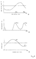
- FIG. 8 shows various characteristic values on a ball for a generic joint according to the prior art, as shown for example in FIG. 1, the angle referred to as the joint rotation angle winkel corresponding to the phase angle ⁇ according to FIG.
- the spatial control angle K shown above has two zero crossings on the circumference of a ball of 360 ° with the joint bent.
- the phase angles ⁇ 01 , ⁇ 02 defined in this way are marked in the representation of the control angle and in the two other representations.
- the supporting forces on the ball which are referred to here as transmission forces F n and which have two maxima and two minima, are shown in the middle. It can be seen that the maximum transmission forces F n are close to the phase angles ⁇ 01 and ⁇ 02 . As a result, the transmission forces F n1 and F n2 are very high at these phase angles.
- the lower illustration shows the rolling error ⁇ v over the phase angle, which has two zero crossings on the orbit of the balls.
- the roll errors ⁇ v 1 , ⁇ v 2 at the phase angles ⁇ 01 and ⁇ 02 which deviate significantly from zero or are close to a maximum, are particularly designated here.
- the roll error .DELTA.v is substantially different from zero, especially with large support forces F n .
- FIGS. 9 to 12 show two of the characteristic values known from FIG. 8 on a ball, each for a joint according to the invention.
- 9 shows the conditions on a joint according to FIG. 3
- FIG. 10 shows the conditions on a joint according to FIG. 4
- FIG. 11 shows the conditions on a joint according to FIG. 5
- FIG. 12 shows the conditions on a joint according to FIG. 6.
- the zero crossings of the spatial control angle K is brought into agreement with the zero crossings of the roll error ⁇ v.
- the discontinuities in the spatial control angle of the joints according to FIGS. 10 and 12 corresponding to the joints according to FIGS. 4 and 6 result from the composite curve shape of the tracks. By approximating this curve, e.g. B. with the help of a polynomial approximation, these discontinuities can be eliminated.
Landscapes
- Engineering & Computer Science (AREA)
- General Engineering & Computer Science (AREA)
- Mechanical Engineering (AREA)
- Rolling Contact Bearings (AREA)
- Pivots And Pivotal Connections (AREA)
- Steering Controls (AREA)
Description
- Fig. 1
- ein bekanntes gattungsgemäßes Kugelgleichlaufdrehgelenk
in Festgelenkbauart
- a) in Axialansicht
- b) im Längsschnitt;
- Fig. 2
- Kugeln eines gattungsgemäßen Gelenks nach Fig. 1 in
verschiedenen Phasenlagen
- a) in Axialansicht auf das Gelenk
- b) im Längsschnitt durch das Gelenk
- Fig. 3
- eine erste erfindungsgemäße Bahngestaltung mit unsymmetrischen
Bahnverläufen
- a) in Axialansicht auf das Gelenk
- b) im Längsschnitt durch das Gelenk;
- Fig. 4
- eine Abwandlung eines Bahnverlaufs nach Figur 3 im Längsschnitt;
- Fig. 5
- eine zweite erfindungsgemäße Bahngestaltung mit Bahnen
enger Krümmung
- a) in Axialansicht auf das Gelenk
- b) im Längsschnitt durch das Gelenk;
- Fig. 6
- eine Abwandlung eines Bahnverlaufs nach Figur 5 im Längsschnitt;
- Fig. 7
- eine konstruktive Ausgestaltung eines Gelenks mit Bahnverläufen nach den Figuren 3 und 5;
- Fig. 8
- Kennwerte an einer Kugel eines gattungsgemäßen Gelenks
nach dem Stand der Technik bei gebeugtem Gelenk über
dem Phasenwinkel, nämlich
- a) räumlicher Steuerwinkel K
- b) Übertragungskräfte Fn
- c) Rollfehler Δv
- Fig. 9
- Kennwerte an einer Kugel eines erfindungsgemäßen Gelenks
nach Figur 3, nämlich
- a) räumlicher Steuerwinkel K
- b) Rollfehler Δv
- Fig. 10
- Kennwerte an einer Kugel eines erfindungsgemäßen Gelenks
nach Figur 4, nämlich
- a) räumlicher Steuerwinkel K
- b) Rollfehler Δv
- Fig. 11
- Kennwerte an einer Kugel eines erfindungsgemäßen Gelenks
nach Figur 5, nämlich
- a) räumlicher Steuerwinkel K
- b) Rollfehler Δv
- Fig. 12
- Kennwerte an einer Kugel eines erfindungsgemäßen Gelenks
nach Figur 6, nämlich
- a) räumlicher Steuerwinkel K
- b) Rollfehler Δv
- Δv -
- Rollfehler
- vkn -
- momentane Geschwindigkeitskomponente am Berührpunkt der Kugelnabe zur Kugel
- vgs -
- momentane Geschwindigkeitskomponente am Berührpunkt des Gelenkstücks zur Kugel
- R0 -
- Radius des Rollkreises der Kugeln
- Rkn -
- Radius von der Gelenkbeugeebene zum Berührpunkt der Kugel mit der Kugelnabe
- Rgs -
- Radius von der Gelenkbeugeebene zum Berührpunkt der Kugel mit dem Gelenkstück
- ωkn -
- Winkelgeschwindigkeit der Kugelnabe
- ωgs -
- Winkelgeschwindigkeit des Gelenkstücks
- ωzgs -
- Vertikalkomponente der Winkelgeschwindigkeit des Gelenkstücks
- ωzkn -
- Vertikalkomponente der Winkelgeschwindigkeit der Kugelnabe
- Θ -
- Phasenwinkel einer Kugel bezogen auf die Gelenkbeugeebene
- δ -
- Druckwinkel der Abstützkräfte auf eine Kugel.
- I -
- ein Kreisbogen um M1
- III -
- eine tangential anschließende Gerade mit einem Winkel mit ca. 6 bis 8° zur Y-Richtung
- IV -
- einen tangential an III anschließenden Kreisbogen um M3
- II -
- einen tangential an IV anschließenden Kreisbogen um M1.
- I -
- ein Kreisbogen um den Mittelpunkt M2I
- III -
- ein tangential an I anschließende Gerade mit einem Winkel von ca. 6 bis 8° zur Y-Achse
- IV -
- einen tangential an III anschließenden Kreisbogen um M3
- II -
- einen tangential an IV anschließenden Kreisbogen um M2II.
Claims (14)
- Kugelgleichlaufdrehgelenk in Festgelenkbauart mit einem Gelenkaußenteil (11) mit innen längsverlaufenden gekrümmten äußeren Kugelbahnen (21), einem Gelenkinnenteil (12) mit außen längsverlaufenden gekrümmten inneren Kugelbahnen (22), einer Mehrzahl von drehmomentübertragenden Kugeln (15), die jeweils in einander zugeordneten äußeren und inneren Kugelbahnen geführt sind, und einem Kugelkäfig (13) mit einer Mehrzahl von Käfigfenstern (14), in denen die Kugeln (15) jeweils aufgenommen sind, wobei die Tangentialebenen an die Kugeln in den bei der Drehmomentübertragung wirksamen Kontaktpunkten der Kugeln (15) mit den äußeren und inneren Kugelbahnen (21, 22) einen räumlichen Steuerwinkel K definieren und wobei die Überlagerung (Superposition) der momentanen örtlichen Relativgeschwindigkeiten in den Kontaktpunkten der äußeren und inneren Kugelbahnen (21, 22) und der Kugeln (15) den Rollfehler Δv definiert,
dadurch gekennzeichnet, daß die Mittellinien der einander zugeordneten äußeren und inneren Kugelbahnen (21, 22) bei gestrecktem Gelenk jeweils in Ebenen BB liegen, die zu radialen Bezugsebenen YZ durch die zusammenfallenden Mittelachsen des Gelenkaußenteils (11) und des Gelenkinnenteils (12) parallel und in übereinstimmendem Umfangssinn versetzt sind, so daß die Kugelbahnen (21, 22) so gestaltet sind, daß bei gebeugtem Gelenk minimale Steuerwinkel K mit Bereichen minimaler Rollfehler Δv zusammenfallen. - Gelenk nach Anspruch 1,
dadurch gekennzeichnet, daß die Ebene BB den Rollkreis R0 der Kugeln (15) bei gestrecktem Gelenk etwa im gleichen Punkt schneidet wie ein Strahl, der von der Bezugsebene YZ um den Kontaktwinkel δ entfernt liegt, wobei der Kontaktwinkel δ als Winkel zwischen den Wirkungslinien der Abstützkräfte an der Kugel (15) und einer Radialen durch die Kugel (15) im Querschnitt durch das gestreckte Gelenk definiert ist. (Figur 3) - Gelenk nach einem der Ansprüche 1 oder 2,
dadurch gekennzeichnet, daß die Mittellinien der einander zugeordneten äußeren und inneren Kugelbahnen (21, 22) bei gestrecktem Gelenk identische Kreisbögen mit einem gemeinsamen Mittelpunkt M1 sind. (Figur 3) - Gelenk nach einem der Ansprüche 1 oder 2,
dadurch gekennzeichnet, daß die Mittellinien der einander zugeordneten äußeren und inneren Kugelbahnen (21, 22) bei gestrecktem Gelenk in einem mittleren Bereich jeweils Kreisbögen mit gegenüber der Mittelebene des gestreckten Gelenks (Rollkreisebene) entgegengesetzt axial und gegenüber den zusammenfallenden Mittelachsen des Gelenkaußenteils (11) und des Gelenkinnenteils (12) radial versetzten Mittelpunkten M3 darstellen. (Figur 4) - Gelenk nach Anspruch 4,
dadurch gekennzeichnet, daß die Kreisbögen in einem Bereich IV einen Winkel von ca. 10 bis 15° überstreichen, an den sich zum einen Ende eine Gerade in einem Bereich III unter ca. 6 bis 8° zu den zusammenfallenden Mittelachsen anschließt und daran wieder ein Kreisbogen in einem Bereich I mit größerem Radius und an den sich zum anderen Ende unmittelbar ein Kreisbogen in einem Bereich II mit größerem Radius anschließt. (Figur 4) - Gelenk nach Anspruch 5,
dadurch gekennzeichnet, daß die beiden Kreisbögen mit größerem Radius einen gemeinsamen Mittelpunkt M1 in der Mittelebene des gestreckten Gelenks (Rollkreisebene) haben. (Figur 4) - Kugelgleichlaufdrehgelenk in Festgelenkbauart mit einem Gelenkaußenteil (11) mit innen längsverlaufenden gekrümmten äußeren Kugelbahnen (21), einem Gelenkinnenteil (12) mit außen längsverlaufenden gekrümmten inneren Kugelbahnen (22), einer Mehrzahl von drehmomentübertragenden Kugeln (15), die jeweils in einander zugeordneten äußeren und inneren Kugelbahnen geführt sind, und einem Kugelkäfig (13) mit einer Mehrzahl von Käfigfenstern (14), in denen die Kugeln (15) jeweils aufgenommen sind, wobei die Tangentialebenen an die Kugeln in den bei der Drehmomentübertragung wirksamen Kontaktpunkten der Kugeln (15) mit den äußeren und inneren Kugelbahnen (21, 22) einen räumlichen Steuerwinkel K definieren und wobei die Überlagerung (Superposition) der momentanen örtlichen Relativgeschwindigkeiten in den Kontaktpunkten der äußeren und inneren Kugelbahnen (21, 22) und der Kugeln (15) den Rollfehler Δv definiert,
dadurch gekennzeichnet, daß die Mittellinien der einander zugeordneten äußeren und inneren Kugelbahnen (21, 22) bei gestrecktem Gelenk in einer radialen Ebene AA durch die zusammenfallenden Mittelachsen des Gelenkaußenteils (11) und des Gelenkinnenteils (12) liegen und Kreisbögen umfassen, deren Krümmungsradius R1 geringer ist als der Rollkreisradius R0, so daß die Kugelbahnen (21, 22) so gestaltet sind, daß bei gebeugtem Gelenk minimale Steuerwinkel K mit Bereichen minimaler Rollfehler Δv zusammenfallen. - Gelenk nach Anspruch 7,
dadurch gekennzeichnet, daß der Krümmungsradius R1 etwa R0 cos2δ beträgt, wobei der Kontaktwinkel δ der Winkel zwischen den Wirkungslinien der Abstützkräfte an der Kugel (15) und einer Radialen durch die Kugel (15) im Querschnitt durch das gestreckte Gelenk ist. (Figur 5) - Gelenk nach Anspruch 7,
dadurch gekennzeichnet, daß die Mittellinien der einander zugeordneten äußeren und inneren Kugelbahnen (21, 22) identische Kreisbögen um einen gemeinsamen Mittelpunkt M2 sind, der in der Mittelebene des gestreckten Gelenks (Rollkreisebene) liegt. (Figur 5) - Gelenk nach Anspruch 7,
dadurch gekennzeichnet, daß die Mittellinien der einander zugeordneten äußeren und inneren Kugelbahnen (21, 22) in einem mittleren Bereich IV jeweils Kreisbögen mit gegenüber der Mittelebene des gestreckten Gelenks (Rollkreisebene) entgegengesetzt axial und gegenüber den zusammenfallenden Mittelachsen radial versetzte Mittelpunkten M3 umfassen. (Figur 6) - Gelenk nach Anspruch 10,
dadurch gekennzeichnet, daß die Kreisbögen in einem Bereich IV einen Winkel von ca. 10 bis 15° überstreichen, an den sich zum einen Ende eine Gerade in einem Bereich III unter ca. 6 bis 8° zu den zusammenfallenden Mittelachsen anschließt und daran wieder ein Kreisbogen in einem Bereich I, und an den sich zum anderen Ende unmittelbar ein Kreisbogen in einem Bereich II anschließt. (Figur 6) - Gelenk nach Anspruch 11,
dadurch gekennzeichnet, daß die abschließenden Kreisbögen Mittelpunkte haben, die in der Mittelebene des gestreckten Gelenks (Rollkreisebene) liegen und die von den zusammenfallenden Mittelachsen jeweils einen Abstand haben, der jeweils etwa sin2δ · R1I bzw. sin2δ · R1II beträgt, wobei der Kontaktwinkel δ als Winkel zwischen den Wirkungslinien der Kräfte an der Kugel (15) und einer Radialen durch die Kugel (15) im Querschnitt durch das gestreckte Gelenk definiert ist. (Figur 6) - Gelenk nach einem der Ansprüche 1 bis 12,
dadurch gekennzeichnet, daß die aus Geraden und Kreisbögen bestehenden Mittellinien angenähert dargestellt werden, z. B. durch Polynomannäherung. - Gelenk nach einem der Ansprüche 1 bis 13,
dadurch gekennzeichnet, daß der Kugelkäfig (13) zur Zwangssteuerung mit einem Pilothebel (29) zusammenwirkt, der Anlenkpunkte auf der Mittelachse des Gelenkaußenteils (11) und auf der Mittelachse des Gelenkinnenteils (12) hat, und mit einem dazwischenliegenden Steuerpunkt (30) am Kugelkäfig (13) angreift. (Figur 7)
Applications Claiming Priority (3)
| Application Number | Priority Date | Filing Date | Title |
|---|---|---|---|
| DE19633166 | 1996-08-17 | ||
| DE19633166A DE19633166C1 (de) | 1996-08-17 | 1996-08-17 | Kugelgleichlaufdrehgelenk mit optimiertem Rollfehler |
| PCT/EP1997/003559 WO1998008000A1 (de) | 1996-08-17 | 1997-07-05 | Kugelgleichlaufdrehgelenk mit optimiertem rollfehler |
Publications (2)
| Publication Number | Publication Date |
|---|---|
| EP0918948A1 EP0918948A1 (de) | 1999-06-02 |
| EP0918948B1 true EP0918948B1 (de) | 2002-01-02 |
Family
ID=7802867
Family Applications (1)
| Application Number | Title | Priority Date | Filing Date |
|---|---|---|---|
| EP97935512A Expired - Lifetime EP0918948B1 (de) | 1996-08-17 | 1997-07-05 | Kugelgleichlaufdrehgelenk mit optimiertem rollfehler |
Country Status (9)
| Country | Link |
|---|---|
| US (1) | US6306044B1 (de) |
| EP (1) | EP0918948B1 (de) |
| JP (1) | JP3795531B2 (de) |
| KR (1) | KR100309978B1 (de) |
| CN (1) | CN1103003C (de) |
| AU (1) | AU3848097A (de) |
| BR (1) | BR9711309A (de) |
| DE (1) | DE19633166C1 (de) |
| WO (1) | WO1998008000A1 (de) |
Families Citing this family (7)
| Publication number | Priority date | Publication date | Assignee | Title |
|---|---|---|---|---|
| US6186899B1 (en) * | 1998-11-25 | 2001-02-13 | Delphi Technologies, Inc. | Constant velocity joint |
| DE10357858A1 (de) * | 2003-12-11 | 2005-07-14 | Sfe Gmbh | Teleskopierbares Antriebsgelenk |
| EP1881218A4 (de) * | 2005-05-12 | 2009-03-04 | Ntn Toyo Bearing Co Ltd | Universelles gleichlauffestgelenk |
| DE502005010536D1 (de) * | 2005-09-23 | 2010-12-23 | Gkn Driveline Int Gmbh | Optimiertes gleichlauffestgelenk mit hinterschnittfreien kugelbahnen |
| JP5840463B2 (ja) | 2011-11-10 | 2016-01-06 | Ntn株式会社 | 固定式等速自在継手 |
| JP6125186B2 (ja) * | 2012-10-12 | 2017-05-10 | Ntn株式会社 | 固定式等速自在継手 |
| CN112334672B (zh) * | 2018-07-05 | 2023-06-06 | Gkn 动力传动系统国际有限责任公司 | 等速万向节 |
Family Cites Families (10)
| Publication number | Priority date | Publication date | Assignee | Title |
|---|---|---|---|---|
| US2128088A (en) * | 1936-08-19 | 1938-08-23 | Hanft Hans | Joint for the connection of shafts |
| US3263448A (en) * | 1963-07-23 | 1966-08-02 | Cam Gears Ltd | Universal joints |
| DE2252827C3 (de) * | 1972-10-27 | 1976-01-08 | Loehr & Bromkamp Gmbh, 6050 Offenbach | Gleichlaufgelenk |
| JPS5776324A (en) * | 1980-10-27 | 1982-05-13 | Toyota Motor Corp | Barfield uniform motion universal joint |
| DE3233753A1 (de) * | 1982-09-11 | 1984-03-15 | Sobhy Labib Dipl.-Ing. 5210 Troisdorf Girguis | Gleichlaufdrehgelenk |
| US4861316A (en) * | 1986-06-11 | 1989-08-29 | Lohr & Bromkamp Gmbh | Constant velocity universal ball joint |
| DE3721775C2 (de) * | 1987-07-01 | 1995-06-29 | Girguis Sobhy Labib | Gleichlauffestgelenk |
| DE3939531C1 (de) * | 1989-11-30 | 1991-06-06 | Loehr & Bromkamp Gmbh, 6050 Offenbach, De | |
| ES2081220T3 (es) * | 1992-02-05 | 1996-02-16 | Gkn Automotive Ag | Junta homocinetica giratoria de bolas provista de elementos de seguridad de jaula. |
| FR2745615B1 (fr) * | 1996-03-04 | 1998-06-12 | Guimbretiere Pierre | Joint homocinetique fixe a billes |
-
1996
- 1996-08-17 DE DE19633166A patent/DE19633166C1/de not_active Expired - Fee Related
-
1997
- 1997-07-05 JP JP51030398A patent/JP3795531B2/ja not_active Expired - Fee Related
- 1997-07-05 AU AU38480/97A patent/AU3848097A/en not_active Abandoned
- 1997-07-05 US US09/242,501 patent/US6306044B1/en not_active Expired - Fee Related
- 1997-07-05 CN CN97197350A patent/CN1103003C/zh not_active Expired - Fee Related
- 1997-07-05 WO PCT/EP1997/003559 patent/WO1998008000A1/de not_active Ceased
- 1997-07-05 EP EP97935512A patent/EP0918948B1/de not_active Expired - Lifetime
- 1997-07-05 BR BR9711309A patent/BR9711309A/pt not_active IP Right Cessation
-
1999
- 1999-02-12 KR KR1019997001244A patent/KR100309978B1/ko not_active Expired - Fee Related
Also Published As
| Publication number | Publication date |
|---|---|
| BR9711309A (pt) | 1999-08-17 |
| JP3795531B2 (ja) | 2006-07-12 |
| CN1103003C (zh) | 2003-03-12 |
| EP0918948A1 (de) | 1999-06-02 |
| KR100309978B1 (ko) | 2001-09-29 |
| JP2000501487A (ja) | 2000-02-08 |
| CN1228145A (zh) | 1999-09-08 |
| WO1998008000A1 (de) | 1998-02-26 |
| US6306044B1 (en) | 2001-10-23 |
| DE19633166C1 (de) | 1998-03-26 |
| KR20000068158A (ko) | 2000-11-25 |
| AU3848097A (en) | 1998-03-06 |
Similar Documents
| Publication | Publication Date | Title |
|---|---|---|
| EP0426186B1 (de) | Gleichlaufdrehgelenk | |
| DE10337612B4 (de) | Gegenbahngelenk mit Steuerwinkelumkehr | |
| DE10060120B4 (de) | Kugelgleichlaufgelenk als Gegenbahngelenk | |
| DE3904655C1 (de) | ||
| DD298540A5 (de) | Gleichlauffestgelenk | |
| DE19704761A1 (de) | Kugelgleichlaufdrehgelenk | |
| WO2002046631A1 (de) | Gleichlauffestgelenk | |
| DE102013103155B4 (de) | Gleichlaufgelenk in Form eines Gegenbahngelenks | |
| DE102004006225B4 (de) | Gleichlaufgelenk mit geringer Radialbewegung der Kugeln | |
| EP1656509A1 (de) | Gegenbahngelenk für grosse beugewinkel | |
| WO2007115607A1 (de) | Spielfreies gleichlaufdrehgelenk | |
| EP0918948B1 (de) | Kugelgleichlaufdrehgelenk mit optimiertem rollfehler | |
| DE19963617C1 (de) | Gleichlauffestgelenke/Käfigmontage in ein Gelenkaußenteil | |
| DE102005042909B4 (de) | Gegenbahngelenk mit begrenzter Axialverschiebung | |
| WO2015000709A1 (de) | Gelenkinnenteil sowie rollenkörper eines tripode-gleichlaufgelenks | |
| DE3426954A1 (de) | Uebertragungsgelenk, insbesondere fuer kraftfahrzeuge | |
| EP3818276B1 (de) | Gleichlaufgelenk | |
| DE19915417C2 (de) | Tripodegelenk mit elastischen Mitteln | |
| EP2912328A1 (de) | Leichtbaugelenk für die übertragung von drehbewegungen | |
| WO2007115606A1 (de) | Spielfreies gleichlaufdrehgelenk | |
| EP1966500A1 (de) | Kugelgleichlauffestgelenk mit grossem beugewinkel | |
| BE1030037B1 (de) | Gelenkgabel für ein Kreuzgelenk, Kreuzgelenk, Lenkwelle eines Kraftfahrzeugs und Lenksystem für ein Kraftfahrzeug | |
| DE102005042910B4 (de) | Gelenkwelle, umfassend ein Gegenbahngelenk mit begrenzter Axialverschiebung | |
| DE102007027315B4 (de) | Gleichlauffestgelenk | |
| WO2014135343A1 (de) | Gleichlaufgelenk |
Legal Events
| Date | Code | Title | Description |
|---|---|---|---|
| PUAI | Public reference made under article 153(3) epc to a published international application that has entered the european phase |
Free format text: ORIGINAL CODE: 0009012 |
|
| 17P | Request for examination filed |
Effective date: 19990211 |
|
| AK | Designated contracting states |
Kind code of ref document: A1 Designated state(s): FR GB IT |
|
| 17Q | First examination report despatched |
Effective date: 20001012 |
|
| GRAG | Despatch of communication of intention to grant |
Free format text: ORIGINAL CODE: EPIDOS AGRA |
|
| GRAG | Despatch of communication of intention to grant |
Free format text: ORIGINAL CODE: EPIDOS AGRA |
|
| GRAH | Despatch of communication of intention to grant a patent |
Free format text: ORIGINAL CODE: EPIDOS IGRA |
|
| GRAG | Despatch of communication of intention to grant |
Free format text: ORIGINAL CODE: EPIDOS AGRA |
|
| GRAH | Despatch of communication of intention to grant a patent |
Free format text: ORIGINAL CODE: EPIDOS IGRA |
|
| GRAA | (expected) grant |
Free format text: ORIGINAL CODE: 0009210 |
|
| RAP1 | Party data changed (applicant data changed or rights of an application transferred) |
Owner name: GKN LOEBRO GMBH |
|
| REG | Reference to a national code |
Ref country code: GB Ref legal event code: IF02 |
|
| AK | Designated contracting states |
Kind code of ref document: B1 Designated state(s): FR GB IT |
|
| GBT | Gb: translation of ep patent filed (gb section 77(6)(a)/1977) |
Effective date: 20020328 |
|
| PGFP | Annual fee paid to national office [announced via postgrant information from national office to epo] |
Ref country code: GB Payment date: 20020611 Year of fee payment: 6 |
|
| ET | Fr: translation filed | ||
| PLBE | No opposition filed within time limit |
Free format text: ORIGINAL CODE: 0009261 |
|
| STAA | Information on the status of an ep patent application or granted ep patent |
Free format text: STATUS: NO OPPOSITION FILED WITHIN TIME LIMIT |
|
| 26N | No opposition filed | ||
| PG25 | Lapsed in a contracting state [announced via postgrant information from national office to epo] |
Ref country code: GB Free format text: LAPSE BECAUSE OF NON-PAYMENT OF DUE FEES Effective date: 20030705 |
|
| GBPC | Gb: european patent ceased through non-payment of renewal fee |
Effective date: 20030705 |
|
| PG25 | Lapsed in a contracting state [announced via postgrant information from national office to epo] |
Ref country code: IT Free format text: LAPSE BECAUSE OF NON-PAYMENT OF DUE FEES Effective date: 20050705 |
|
| PGFP | Annual fee paid to national office [announced via postgrant information from national office to epo] |
Ref country code: FR Payment date: 20120803 Year of fee payment: 16 |
|
| REG | Reference to a national code |
Ref country code: FR Ref legal event code: ST Effective date: 20140331 |
|
| PG25 | Lapsed in a contracting state [announced via postgrant information from national office to epo] |
Ref country code: FR Free format text: LAPSE BECAUSE OF NON-PAYMENT OF DUE FEES Effective date: 20130731 |