EP0918968B1 - Dispositif d'accouplement pour realiser un raccord de tuyaux - Google Patents
Dispositif d'accouplement pour realiser un raccord de tuyaux Download PDFInfo
- Publication number
- EP0918968B1 EP0918968B1 EP97941929A EP97941929A EP0918968B1 EP 0918968 B1 EP0918968 B1 EP 0918968B1 EP 97941929 A EP97941929 A EP 97941929A EP 97941929 A EP97941929 A EP 97941929A EP 0918968 B1 EP0918968 B1 EP 0918968B1
- Authority
- EP
- European Patent Office
- Prior art keywords
- sleeve
- assembly according
- pipe assembly
- pipe
- compression
- Prior art date
- Legal status (The legal status is an assumption and is not a legal conclusion. Google has not performed a legal analysis and makes no representation as to the accuracy of the status listed.)
- Expired - Lifetime
Links
Images


Classifications
-
- F—MECHANICAL ENGINEERING; LIGHTING; HEATING; WEAPONS; BLASTING
- F16—ENGINEERING ELEMENTS AND UNITS; GENERAL MEASURES FOR PRODUCING AND MAINTAINING EFFECTIVE FUNCTIONING OF MACHINES OR INSTALLATIONS; THERMAL INSULATION IN GENERAL
- F16L—PIPES; JOINTS OR FITTINGS FOR PIPES; SUPPORTS FOR PIPES, CABLES OR PROTECTIVE TUBING; MEANS FOR THERMAL INSULATION IN GENERAL
- F16L13/00—Non-disconnectable pipe joints, e.g. soldered, adhesive, or caulked joints
- F16L13/14—Non-disconnectable pipe joints, e.g. soldered, adhesive, or caulked joints made by plastically deforming the material of the pipe, e.g. by flanging, rolling
- F16L13/141—Non-disconnectable pipe joints, e.g. soldered, adhesive, or caulked joints made by plastically deforming the material of the pipe, e.g. by flanging, rolling by crimping or rolling from the outside
- F16L13/142—Non-disconnectable pipe joints, e.g. soldered, adhesive, or caulked joints made by plastically deforming the material of the pipe, e.g. by flanging, rolling by crimping or rolling from the outside with a sealing element inserted into the female part before crimping or rolling
Definitions
- the invention relates to a tube arrangement with two ends pipes connected by a coupling device.
- GB-A-1 213 786 proposed to provide the pipes with bellows-like areas, which absorb the changes in length of the pipe and thus to relieve the connection point. Furthermore is in that formed between two nested pipe ends Annular space provided a sealing element, which in the It is able to at least partially compensate for radial expansion. With this embodiment, thermal expansions can to be partially offset.
- the object of the invention is therefore to provide a pipe arrangement create a simple, secure and tight connection of two pipe ends even with high temperature fluctuations guaranteed.
- This object is essentially achieved according to the invention through a tube arrangement with at least two ends a coupling device connected pipes, the coupling device at least one attached to a pipe end and has a compression sleeve pressed to the tube end and between Press sleeve and tube end provided an elastic area is who has such elasticity and is so formed is that thermal axial and radial expansions occurring during operation of the pipe end by elastic deformation of the elastic range without slipping the pipe end in the Press sleeve are added.
- the elastic area is designed so that both changes in thickness and changes in length of the pipe end pressed into the coupling device can be.
- the elastic region is expediently designed such that that the tensile and shear elasticity towards the free end the press sleeve increase.
- This measure corresponds to the deformation behavior of the elastic area the longitudinal expansion behavior one held in the coupling device Tube, since this is in the area of the free end of the Press sleeve the strongest and its inserted into the press sleeve axial end practically no longer practically stretches because the longitudinal forces have already been absorbed by then are.
- a pipe arrangement is the compression sleeve by a plastically deformable Outer sleeve, which can consist of metal, for example, and an elastically deformable held in the outer sleeve Ring element formed, hereinafter referred to as the inner sleeve will, although not the stiffness of a sleeve in conventional Has sense.
- the inner sleeve expediently consists like the pipes made of plastic. This ensures that the pipe end and the inner sleeve approximately in deform to the same extent.
- the outer sleeve and the inner sleeve can also be conical, so that the Inner sleeve from the free end of the compression sleeve into the outer sleeve can be inserted, and the inner sleeve can additionally with elastic deformation of a spring element in the Outer sleeve to be pressed in to the required compression to produce between the press sleeve and the pipe end.
- a releasable connection is created because the outer sleeve does not need to be plastically deformed.
- the inner sleeve can also be axially adjacent to one another subsequent and separately provided Be formed inner sleeve elements. Then have the inner sleeve elements expediently a T-shaped or L-shaped cross section, so that in axial alignment to the pipe end open incisions are formed.
- the individual inner sleeve elements can consist of metal, for example.
- the press sleeve is made from an elastically deformable plastic body with it embedded, plastically deformable fibers or ring elements made of metal or plastic.
- the press sleeve be designed as an injection molded part, so that their manufacture is simple.
- the plastic is the desired one Elasticity of the compression sleeve reached while through the fibers or rings are used to fix a pipe end, by being pressed inward under plastic deformation are, whereby the tube end and the press sleeve pressed together become.
- the desired increase in Longitudinal or shear elasticity in the direction of the free end of the Press sleeve can be reached by pressing the one in the direction their free end has decreasing wall thickness.
- the press sleeve incisions are provided to increase the elasticity his.
- a Support sleeve may be provided which with the press sleeve an annular receptacle forms for a pipe end.
- the support sleeve can also in the area of their outer surface coming into contact with the pipe end be elastic to stretch the pipe end to be able to absorb through elastic deformation.
- the compression sleeve and support sleeve in one piece as Plastic part with plastically deformable embedded therein Fibers or rings are made.
- the Support sleeve like the compression sleeve one towards its free end decreasing wall thickness and on its outer surface Have incisions.
- the compression sleeve can be in its circumferential direction be divided into several sleeve elements that together under elastic prestressing of spring elements are connected such that the compression sleeve opposes the Preload of the spring elements can expand radially, and the are resilient in the axial direction.
- the sleeve elements are expediently compressed by compression spring elements and have elastically compressible and in the axial direction stretchable radial bulges.
- the press sleeve is made made of an elastically deformable material and has a cavity, the for pressing the compression sleeve with a pipe end under Widening of the press sleeve can be filled with press liquid is.
- a powder in the cavity Means to provide that when arousal, in particular an inflammation or reaction with water, with widening the press sleeve reacts expanding.
- the press sleeve is expedient surrounded by a solid reinforcement sleeve, so that a Widening of the compression sleeve essentially radially inwards Direction of the pipe end to be fixed.
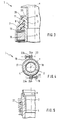
- the pipe arrangement shown in Figure 1 comprises a coupling device 1 with a substantially cylindrical Support sleeve 2 and a likewise substantially cylindrical Press sleeve 3.
- a pipe end 4 which Plastic or metal can exist.
- the compression sleeve 3 consists of a plastically deformable outer sleeve 7 and an inner sleeve held in the outer sleeve 7 8th.
- the inner sleeve 8 consists of a plastic, which is such is elastically deformable that radial expansion of the pipe end 4 due to temperature changes due to elastic deformation the inner sleeve 8 and longitudinal expansions of the pipe end 4 by shear deformation or by longitudinal elasticity without the pipe end 4 slipping in the compression sleeve 3.
- the inner sleeve 8 In its inner surface 6 coming into contact with the pipe end 4 the inner sleeve 8 has a plurality of incisions 11, which lie next to each other in the axial direction X of the press sleeve 3 and extend over the entire circumference of the press sleeve 3.
- the Incisions 11 are provided to increase the elasticity of the inner sleeve 8 increase and in particular to create freedom in the plastic material of the inner sleeve 8 in the event of deformation can dodge.
- the depth and / or width of the cuts 11 is from the expedient axial end of the Tube 4 to the free end of the compression sleeve 3 increasingly larger. This is relieved that the shear elasticity the inner sleeve 8 at the free end of the compression sleeve 3, where the strongest longitudinal strains of the pipe end 4 occur, the greatest is.
- the outer sleeve 7 is with the support sleeve 2 via a connecting web 25 connected to a stop surface 26 for the Pipe end 4 and the inner sleeve 8 forms and the occurring Can transmit pipe forces as well as contributes to the sealing.
- the inner sleeve 8 With reduction the incisions 11 is elastically deformed, as in the right half of Figure 1 is shown. The generated by this Preloading the inner sleeve 8 ensures a secure hold of the pipe end 4 in the coupling device 1.
- the inner sleeve can also be axially adjacent to one another subsequent and separately provided Be formed inner sleeve elements. Then have the inner sleeve elements conveniently a T or L-shaped cross section, so that in axial alignment to the pipe end open incisions are formed.
- the individual inner sleeve elements can consist of metal, for example.
- the tube 4 expands both in its length and also strong in its thickness.
- This thermally conditioned Strains are in the coupling device 1 by a elastic deformation of the inner sleeve 8 compensated without the pipe end 4 slips in the coupling device 1.
- the coupling device 1 shown in Figure 2 corresponds essentially the coupling device shown in Figure 1 and comprises a support sleeve 2 and a press sleeve 3, which form an annular space 12 between them, into which a pipe end 4 is inserted.
- the compression sleeve 3 consists of a the tube end 4 enclosing, elastically deformable inner sleeve 8, in their inner surface 6 Incisions 11, and one surrounding the inner sleeve 8 plastically deformable outer sleeve 7 made of metal.
- Fixing the pipe end 4 in the coupling device 1 takes place as in the embodiment shown in FIG. 1, by the outer sleeve 7 with plastic deformation over its whole circumference is pressed radially inwards, so that the inner sleeve 8 is elastically deformed, as a result of which the pipe end 4 clamped under tension between inner sleeve 8 and support sleeve 2 becomes.
- outer sleeve 7 and / or support sleeve 2 from a so-called memory material, i.e. an alloy with shape memory, which exist at a given Heating expands or contracts so that a tube end 4 inserted in the annular space 12 between the sleeves 2, 7 clamped under elastic deformation of the inner sleeve 8 becomes.
- a so-called memory material i.e. an alloy with shape memory, which exist at a given Heating expands or contracts so that a tube end 4 inserted in the annular space 12 between the sleeves 2, 7 clamped under elastic deformation of the inner sleeve 8 becomes.
- FIG 3 is a third tube assembly with a coupling device 1 shown.
- the compression sleeve 3rd also from an outer sleeve connected to the support sleeve 2 7 and one inserted between tubes and outer sleeve 7 Inner sleeve 8 formed.
- the outer sleeve 7 and the inner sleeve 8 are each conical, so that the Inner sleeve 8 wedge-like in between the outer sleeve 7 and the pipe end 4 formed annular space with elastic deformation from free end of the compression sleeve 3 can be inserted.
- the inner sleeve 8 is on its inner surface abutting the pipe end 4 6 again with incisions 11 to Longitudinal forces in the pipe to reduce the pipe expansion without slippage and Alternative rooms for greater thermal expansion of plastic compared Creating metal.
- the coupling device shown in Figures 4 and 5 of a pipe arrangement according to the invention has a support sleeve 2 and a press sleeve 3, which has an annular space 12 between them form, into which a pipe end 4 is inserted.
- the press sleeve 3 is divided here into two or more in the circumferential direction Sleeve elements 17, 18 which grip around the pipe end 4 and on their mutually facing end faces each under elastic Preload of compression spring elements 19 connected in this way are that the compression sleeve 3 against the bias of the Compression spring elements 19 can expand radially.
- the sleeve elements 17, 18 are also, as in particular in Figure 5 can be seen, resilient in the axial direction X of the tube 4 formed to compensate for longitudinal expansions of the pipe end 4 to be able to do what they are several with an axial distance between them radial bulges arranged in the manner of cup springs 27 have.
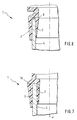
- Figures 6 and 7 show two further pipe arrangements, at which the support sleeve 2 and the compression sleeve 3 of the coupling device 1 each formed in one piece as injection molded parts are.
- the material used for the injection molded parts here is elastic deformable plastic chosen in the plastically deformable Fibers 9 or ring elements 10 are embedded.
- Ring elements 10 on the outside surround the compression sleeve 3 or be inserted into it.
- the coupling device shown in Figure 9 does not include any Support sleeve, but only a compression sleeve 3, which is on a pipe end 4 is postponed.
- the compression sleeve 3 consists of an elastic deformable plastic material and has one over the entire circumference extending cavity 21.
- the cavity 21 can be powdered in particular Means can be filled, for example by a Inflammation or other arousal can be expanded while expanding the compression sleeve 3.
- the compression sleeve 3 is surrounded by a reinforcement sleeve 20, which is made of a very strong material, so that the expansion the compression sleeve 3 practically exclusively radially is done inside towards the pipe end 4.
Landscapes
- Engineering & Computer Science (AREA)
- General Engineering & Computer Science (AREA)
- Mechanical Engineering (AREA)
- Quick-Acting Or Multi-Walled Pipe Joints (AREA)
- Joints With Sleeves (AREA)
Claims (31)
- Raccord de tuyaux comprenant au moins deux tuyaux assemblés par leurs extrémités à l'aide d'un dispositif d'accouplement (1), le dispositif d'accouplement (1) présentant au moins un manchon de compression (3) enfoncé sur une extrémité de tuyau (4, 5) et comprimé sur l'extrémité de tuyau (4, 5) et une zone élastique étant prévue entre le manchon de compression (3) et l'extrémité du tuyau (4, 5), qui possède une élasticité telle et est réalisée de telle manière que les allongements axiaux et radiaux dus à la chaleur de l'extrémité du tuyau (4, 5), qui se produisent pendant le fonctionnement, sont absorbés par déformation élastique de la zone élastique sans que l'extrémité du tuyau (4, 5) ne glisse dans le manchon de compression (3).
- Raccord de tuyaux selon la revendication 1, caractérisé en ce que l'élasticité de la zone élastique augmente en direction de l'extrémité libre du manchon de compression (3).
- Raccord de tuyaux selon la revendication 2, caractérisé en ce que plusieurs entailles (11) pour augmenter l'élasticité sont prévues dans la surface intérieure (6) de la zone élastique, qui sont disposées côte à côte dans la direction de l'axe (X) du manchon de compression (3) en s'étendant dans la direction du pourtour de ce dernier.
- Raccord de tuyaux selon la revendication 3, caractérisé en ce que la profondeur et/ou la largeur des entailles (11) augmente vers l'extrémité libre du manchon de compression (3).
- Raccord de tuyaux selon l'une des revendications 1 à 4, caractérisé en ce que le manchon de compression (3) présente une douille extérieure (7) et une douille intérieure (8) fixée dans la douille extérieure (7) et formant la zone élastique.
- Raccord de tuyaux selon la revendication 5, caractérisé en ce que la douille intérieure (8) est composée de matière plastique déformable élastiquement.
- Raccord de tuyaux selon la revendication 5 ou 6, caractérisé en ce que la douille extérieure (7) et la douille intérieure (8) sont réalisées de manière à ce que la douille intérieure (8) puisse être insérée dans la douille extérieure (7) par l'extrémité libre du manchon de compression (3).
- Raccord de tuyaux selon la revendication 7, caractérisé en ce que la douille extérieure (7) et la douille intérieure (8) sont chacune réalisées de façon conique.
- Raccord de tuyaux selon la revendication 7 ou 8, caractérisé en ce que la douille intérieure (8) peut être enfoncée axialement dans la douille extérieure (7) en la déformant de façon élastique afin de créer la compression entre le manchon de compression (3) et l'extrémité du tuyau (4, 5).
- Raccord de tuyaux selon la revendication 9, caractérisé en ce que la douille intérieure (8) est enfoncée dans la douille extérieure (7) du fait de la précontrainte d'un élément à ressort (15) qui prend appui entre la douille intérieure (8) et un élément de fixation (16) vissé de l'extérieur dans la douille extérieure (7).
- Raccord de tuyaux selon l'une des revendications 5 à 10, caractérisé en ce que la douille intérieure (8) est formée par une multitude d'éléments de douille intérieure séparés les uns des autres et faisant suite les uns aux autres dans la direction axiale.
- Raccord de tuyaux selon la revendication 11, caractérisé en ce que les éléments de douille intérieure possèdent chacun une section transversale en T ou en L, si bien qu'en les disposant en rang côte à côte dans la direction de l'axe, ils forment des entailles ouvertes en direction de l'extrémité du tuyau.
- Raccord de tuyaux selon la revendication 11 ou 12, caractérisé en ce que les éléments de douille intérieure sont en métal.
- Raccord de tuyaux selon l'une des revendications 1 à 4, caractérisé en ce que le manchon de compression (3) présente un corps en matière plastique déformable de façon élastique, dans lequel sont enrobées des fibres (9) en métal ou en matière plastique déformables de façon plastique.
- Raccord de tuyaux selon l'une des revendications 1 à 4, caractérisé en ce que le manchon de compression (3) présente un corps en matière plastique déformable de façon élastique, dans lequel sont noyés des éléments annulaires (10) en métal ou en matière plastique déformables de façon plastique.
- Raccord de tuyaux selon la revendication 15, caractérisé en ce que les éléments annulaires (10) sont noyés dans la surface extérieure du corps en matière plastique.
- Raccord de tuyaux selon l'une des revendications 14 à 16, caractérisé en ce que le corps en matière plastique possède une épaisseur de paroi allant en diminuant vers l'extrémité libre du manchon de compression (3).
- Raccord de tuyaux selon l'une des revendications 1 à 17, caractérisé en ce qu'à l'intérieur du manchon de compression (3) est prévu un manchon de support (2) qui constitue avec le manchon de compression (3) un logement annulaire (12) pour une extrémité de tuyau (4, 5).
- Raccord de tuyaux selon la revendication 18, caractérisé en ce que le manchon de compression (3) et le manchon de support (2) sont reliés fixement entre eux.
- Raccord de tuyaux selon la revendication 19, caractérisé en ce que le manchon de compression (3) et le manchon de support (2) sont réalisés d'un seul tenant en tant que pièce en matière plastique élastique dans laquelle sont enrobés des fibres (9) ou des éléments annulaires (10) en métal ou en matière plastique déformables de façon plastique.
- Raccord de tuyaux selon la revendication 20, caractérisé en ce que le manchon de support (2) présente une épaisseur de paroi allant en diminuant vers son extrémité libre.
- Raccord de tuyaux selon l'une des revendications 18 à 21, caractérisé en ce que dans la surface extérieure (13) du manchon de support (2) qui entre en contact avec une extrémité de tuyau (4, 5) sont prévues plusieurs entailles pour augmenter l'élasticité, qui sont disposées côte à côte dans la direction de l'axe (X) du manchon de compression (3) en s'étendant dans la direction du pourtour de ce dernier et qui sont de préférence réalisées de façon annulaire.
- Raccord de tuyaux selon la revendication 22, caractérisé en ce que la profondeur et/ou la largeur des entailles augmente en direction de l'extrémité libre du manchon de support (2).
- Raccord de tuyaux selon la revendication 19, caractérisé en ce que le manchon de support (2) et une douille extérieure (7) du manchon de compression (3) sont coulés à l'une de leurs extrémités axiales dans un élément d'accouplement (21) en matière plastique.
- Raccord de tuyaux selon la revendication 24, caractérisé en ce que le manchon de support (2) et la douille extérieure (7) sont composés d'une matière à mémoire de forme.
- Raccord de tuyaux selon la revendication 1, caractérisé en ce que le manchon de compression (3) est subdivisé dans la direction de son pourtour en plusieurs éléments de manchon (17, 18) qui sont reliés entre eux avec une précontrainte élastique par des éléments à ressort (19) de manière à ce que le manchon de compression (3) puisse s'élargir radialement à l'encontre de la précontrainte des éléments à ressort (19), et qui sont réalisés de manière à faire ressort dans la direction axiale.
- Raccord de tuyaux selon la revendication 26, caractérisé en ce que les éléments de manchon (17, 18) sont comprimés élastiquement par des éléments de compression à ressort (19).
- Raccord de tuyaux selon la revendication 26 ou 27, caractérisé en ce que, pour créer une élasticité dans la direction axiale, les éléments de manchon (17, 18) présentent des convexités (27) radiales disposées avec un écart axial réciproque, qui peuvent s'allonger et être comprimées de façon élastique dans la direction axiale.
- Raccord de tuyaux selon l'une des revendications 1 à 4, caractérisé en ce que le manchon de compression (3) est composé d'une matière déformable élastiquement et présente une cavité (21) qui, pour comprimer le manchon de compression (3) sur une extrémité de tuyau (4, 5) en élargissant le manchon de compression (3), peut être remplie de liquide de compression.
- Raccord de tuyaux selon l'une des revendications 1 à 4, caractérisé en ce que le manchon de compression (3) est composé d'une matière déformable élastiquement et présente une cavité (21) qui est notamment remplie d'une matière pulvérulente qui, notamment lorsqu'elle est amorcée ou mise en contact avec de l'eau, réagit par expansion et élargit ce faisant le manchon de compression (3).
- Raccord de tuyaux selon la revendication 29 ou 30, caractérisé en ce que le manchon de compression (3) est entouré par une douille de renforcement (20) statique, si bien que le manchon de compression (3) s'élargit essentiellement radialement vers l'intérieur en direction de l'extrémité du tuyau (4, 5).
Applications Claiming Priority (3)
| Application Number | Priority Date | Filing Date | Title |
|---|---|---|---|
| DE19633627 | 1996-08-21 | ||
| DE19633627A DE19633627A1 (de) | 1996-08-21 | 1996-08-21 | Kupplungsvorrichtung für die Herstellung einer Rohrverbindung |
| PCT/EP1997/004349 WO1998008017A2 (fr) | 1996-08-21 | 1997-08-09 | Dispositif d'accouplement pour realiser un raccord de tuyaux |
Publications (2)
| Publication Number | Publication Date |
|---|---|
| EP0918968A2 EP0918968A2 (fr) | 1999-06-02 |
| EP0918968B1 true EP0918968B1 (fr) | 2001-11-14 |
Family
ID=7803183
Family Applications (1)
| Application Number | Title | Priority Date | Filing Date |
|---|---|---|---|
| EP97941929A Expired - Lifetime EP0918968B1 (fr) | 1996-08-21 | 1997-08-09 | Dispositif d'accouplement pour realiser un raccord de tuyaux |
Country Status (5)
| Country | Link |
|---|---|
| US (1) | US6354634B1 (fr) |
| EP (1) | EP0918968B1 (fr) |
| AU (1) | AU4379597A (fr) |
| DE (2) | DE19633627A1 (fr) |
| WO (1) | WO1998008017A2 (fr) |
Families Citing this family (11)
| Publication number | Priority date | Publication date | Assignee | Title |
|---|---|---|---|---|
| DE29720053U1 (de) | 1997-11-12 | 1999-03-18 | Meteor Gummiwerke K. H. Bädje GmbH & Co, 31167 Bockenem | Dichtungsverbindungselement, Dichtungsendstück und Dichtung |
| JP3452196B2 (ja) * | 2000-08-31 | 2003-09-29 | 株式会社フロウエル | チューブ継手および、その施工方法 |
| KR100411709B1 (ko) * | 2001-05-11 | 2003-12-18 | 한국과학기술연구원 | 형상기억합금을 이용한 파이프 연결방법 |
| US20080314466A1 (en) * | 2007-06-22 | 2008-12-25 | Cimberio Valve Co. Inc. | Valves for use with tankless water heater |
| US8109297B2 (en) * | 2009-02-12 | 2012-02-07 | Fimcim Spa | Valve arrangement for use with a water meter |
| US9157643B2 (en) | 2010-10-14 | 2015-10-13 | Fimcim S.P.A. | Conditioning plant |
| DE102013223277A1 (de) * | 2013-11-14 | 2015-05-21 | Bombardier Transportation Gmbh | Stange und Bausatz, insbesondere für Fahrzeuge zur Beförderung von Personen im öffentlichen Nah- und Fernverkehr |
| JP7503990B2 (ja) * | 2020-10-06 | 2024-06-21 | タイコエレクトロニクスジャパン合同会社 | シール構造体 |
| US11788655B2 (en) | 2021-07-20 | 2023-10-17 | General Electric Company | Tube coupling |
| US12129945B2 (en) | 2021-07-20 | 2024-10-29 | General Electric Company | Tube assembly |
| US11802640B2 (en) | 2021-07-20 | 2023-10-31 | General Electric Company | Tube coupling |
Family Cites Families (26)
| Publication number | Priority date | Publication date | Assignee | Title |
|---|---|---|---|---|
| US1817774A (en) * | 1928-05-02 | 1931-08-04 | Harry E Sipe | Tubular coupling and method of constructing the same |
| US1786720A (en) * | 1929-08-28 | 1930-12-30 | Ohio Brass Co | Current-collector support |
| US2032492A (en) * | 1934-10-31 | 1936-03-03 | Goodrich Co B F | Pipe joint assembly |
| GB556010A (en) * | 1942-07-09 | 1943-09-16 | Charles Wyndham Hayes | Improvements in or relating to pipe joints or couplings |
| US2451070A (en) * | 1945-03-12 | 1948-10-12 | Us Stoneware Co | Fluid-retaining joint and method of making the same |
| US2448769A (en) * | 1945-09-07 | 1948-09-07 | James M W Chamberlain | Fluid-coupling assembly |
| DE807575C (de) | 1948-10-02 | 1951-07-02 | Klaue Hermann | Schlaucharmatur |
| GB870952A (en) * | 1958-03-25 | 1961-06-21 | Bagnulo Luigi | A permanent joint device for pipes and the like |
| DE1187870B (de) | 1958-10-01 | 1965-02-25 | Aga Plaatfoeraedling Aktiebola | Plastisch verformbare metallische Kupplungshuelse zum Verbinden von Metallrohren mit glatten Enden |
| US3226137A (en) * | 1962-04-16 | 1965-12-28 | Otto A Trnka | Fire-hose mender |
| AT270313B (de) * | 1964-11-24 | 1969-04-25 | Immanuel Straub | Rohrkupplung |
| FR2002864A1 (fr) | 1968-02-29 | 1969-10-31 | Daimler Benz Ag | |
| FI55906C (fi) * | 1968-09-19 | 1979-10-10 | Aga Ab | Skarvdon foer foerbindning av pao utsidan slaeta roer |
| GB1249839A (en) * | 1968-12-21 | 1971-10-13 | Luigi Bagnulo | Electrically insulating joint for metallic pipe lines |
| NO136223C (no) * | 1973-02-27 | 1977-08-03 | Sentralinstituttet For Ind For | Fremgangsm}te til } skaffe en fast og fortrinnsvis tett forbindelse mellom et hovedsakelig sylindrisk indre legeme og et hovedsakelig sylindrisk ytre legeme som omgir det indre, og middel til utf¦relse av fremgangsm}ten. |
| US4198078A (en) * | 1978-07-17 | 1980-04-15 | Aeroquip Corporation | Pressurized vibration isolator |
| NL177516C (nl) * | 1978-09-12 | 1985-10-01 | Pidou Bv | Afdichtmanchet. |
| FR2450990A1 (fr) | 1979-03-09 | 1980-10-03 | Mosettig Jean | Dispositif d'etancheite d'un manchon a un conducteur electrique isole ou a un tuyau et procede de realisation d'un joint tubulaire d'etancheite au moyen de ce dispositif |
| US4427219A (en) * | 1981-01-26 | 1984-01-24 | Robroy Industries | Compression coupling |
| DE3310027C2 (de) * | 1983-03-19 | 1985-01-17 | Karl Heinz 3353 Bad Gandersheim Vahlbrauk | Vorrichtung zum Verbinden der Enden zweier Rohre oder Rohrformstücke |
| IT1223852B (it) * | 1988-09-27 | 1990-09-29 | Viscardo Baldoni | Motociclo ripiegabile |
| ES2033520T3 (es) | 1988-09-30 | 1993-03-16 | Mannesmann Aktiengesellschaft | Procedimiento y dispositivo y racor de presion para la fabricacion de una union hermetica indisoluble de tubos. |
| DE9016310U1 (de) * | 1990-11-30 | 1991-02-21 | Hewing GmbH, 4434 Ochtrup | Rohrverbindung, insbesondere an Verbundrohren |
| DE4137495C2 (de) * | 1991-11-14 | 1995-10-05 | Karl Heinz Vahlbrauk | Rohrverbindung für Druckrohre |
| DE59307976D1 (de) * | 1992-07-07 | 1998-02-19 | Stebi Tech Ag | Zur Herstellung einer Rohrverbindung dienende Kupplungsvorrichtung |
| DK170882B1 (da) | 1993-04-19 | 1996-02-26 | Ole Lindhardt | Rørkobling og fremgangsmåde til brug af en sådan |
-
1996
- 1996-08-21 DE DE19633627A patent/DE19633627A1/de not_active Ceased
-
1997
- 1997-08-09 DE DE59705402T patent/DE59705402D1/de not_active Expired - Lifetime
- 1997-08-09 WO PCT/EP1997/004349 patent/WO1998008017A2/fr not_active Ceased
- 1997-08-09 AU AU43795/97A patent/AU4379597A/en not_active Abandoned
- 1997-08-09 EP EP97941929A patent/EP0918968B1/fr not_active Expired - Lifetime
- 1997-08-09 US US09/242,563 patent/US6354634B1/en not_active Expired - Fee Related
Also Published As
| Publication number | Publication date |
|---|---|
| EP0918968A2 (fr) | 1999-06-02 |
| AU4379597A (en) | 1998-03-06 |
| US6354634B1 (en) | 2002-03-12 |
| DE59705402D1 (de) | 2001-12-20 |
| DE19633627A1 (de) | 1998-02-26 |
| WO1998008017A3 (fr) | 1998-05-07 |
| WO1998008017A2 (fr) | 1998-02-26 |
Similar Documents
| Publication | Publication Date | Title |
|---|---|---|
| DE69900615T2 (de) | Vorrichtung zum Verbinden einer Rohrkupplung | |
| EP0212331B1 (fr) | Raccordement de deux tuyaux d'une conduite pour milieux chauds | |
| DE69713447T2 (de) | Rohrverbindungsvorrichtung mit Zapfen- und Muffen-Teilen die entsprechende kegelstumpfförmige Flächen aufweisen | |
| DE69425667T2 (de) | Rohrverbindung | |
| EP2245353B1 (fr) | Elément d'ancrage pour des raccords de tuyauterie | |
| DE3336855A1 (de) | Schubgesicherte steckverbindung fuer rohre, insbesondere muffenrohre | |
| EP1888960B1 (fr) | Element d'ancrage destine a des couplages de tubes | |
| DE102010061006A1 (de) | Kupplung, insbesondere für das Verbinden von Ankerstangen | |
| WO1998008017A2 (fr) | Dispositif d'accouplement pour realiser un raccord de tuyaux | |
| DE2621044B2 (de) | Rohrverbindung | |
| DE69835404T2 (de) | Abdichtungsummantelungseinheit für ein Kunststoffrohr | |
| EP0913612A1 (fr) | Procédé de connexion d'un tuyau avec un raccord de tuyau, une connexion entre un tuyau et un raccord de tuyau ainsi qu'un raccord de tuyau pour ceci | |
| DE69907592T2 (de) | Vorrichtung zum Schnellverbinden von Rohren | |
| DE2927716A1 (de) | Fluid-verbindungsstueck | |
| DE3230932C2 (de) | Kupplung | |
| DE7615588U1 (de) | Drehschwingungsdämpfer | |
| EP1930605A1 (fr) | Raccord pour tuyau, en particulier tuyau en plastique ou composite de métal / plastique | |
| EP2827042A1 (fr) | Raccord de tuyauterie pour le passage d'un fluide sous pression | |
| EP0575727A1 (fr) | Joint de tuyau | |
| EP3270027B1 (fr) | Segment de conduite comprenant deux tubes de fonçage reliés ensemble | |
| EP1887271B1 (fr) | Bague d'étanchéité | |
| DE3203144A1 (de) | Verfahren zur druckdichten befestigung eines rohres in einem rohrboden o.dgl. | |
| DE2808696A1 (de) | Klemmverbindung | |
| EP1507997B1 (fr) | Dispositif servant a compenser des variations de longueur dans un systeme de canalisations | |
| EP1043535A1 (fr) | Dispositif de raccordement d'éléments de tuyauterie |
Legal Events
| Date | Code | Title | Description |
|---|---|---|---|
| PUAI | Public reference made under article 153(3) epc to a published international application that has entered the european phase |
Free format text: ORIGINAL CODE: 0009012 |
|
| 17P | Request for examination filed |
Effective date: 19981212 |
|
| AK | Designated contracting states |
Kind code of ref document: A2 Designated state(s): DE FR IT SE |
|
| GRAG | Despatch of communication of intention to grant |
Free format text: ORIGINAL CODE: EPIDOS AGRA |
|
| GRAG | Despatch of communication of intention to grant |
Free format text: ORIGINAL CODE: EPIDOS AGRA |
|
| GRAH | Despatch of communication of intention to grant a patent |
Free format text: ORIGINAL CODE: EPIDOS IGRA |
|
| 17Q | First examination report despatched |
Effective date: 20001212 |
|
| GRAH | Despatch of communication of intention to grant a patent |
Free format text: ORIGINAL CODE: EPIDOS IGRA |
|
| GRAA | (expected) grant |
Free format text: ORIGINAL CODE: 0009210 |
|
| AK | Designated contracting states |
Kind code of ref document: B1 Designated state(s): DE FR IT SE |
|
| RAP2 | Party data changed (patent owner data changed or rights of a patent transferred) |
Owner name: NOVOPRESS GMBH PRESSEN UND PRESSWERKZEUGE & CO. KG |
|
| RIN2 | Information on inventor provided after grant (corrected) |
Free format text: DISCHLER, HELMUT, DIPL.-ING. |
|
| REF | Corresponds to: |
Ref document number: 59705402 Country of ref document: DE Date of ref document: 20011220 |
|
| PGFP | Annual fee paid to national office [announced via postgrant information from national office to epo] |
Ref country code: FR Payment date: 20020819 Year of fee payment: 6 |
|
| PGFP | Annual fee paid to national office [announced via postgrant information from national office to epo] |
Ref country code: SE Payment date: 20020823 Year of fee payment: 6 |
|
| PLBE | No opposition filed within time limit |
Free format text: ORIGINAL CODE: 0009261 |
|
| STAA | Information on the status of an ep patent application or granted ep patent |
Free format text: STATUS: NO OPPOSITION FILED WITHIN TIME LIMIT |
|
| 26N | No opposition filed | ||
| PG25 | Lapsed in a contracting state [announced via postgrant information from national office to epo] |
Ref country code: SE Free format text: LAPSE BECAUSE OF NON-PAYMENT OF DUE FEES Effective date: 20030810 |
|
| EUG | Se: european patent has lapsed | ||
| PG25 | Lapsed in a contracting state [announced via postgrant information from national office to epo] |
Ref country code: FR Free format text: LAPSE BECAUSE OF NON-PAYMENT OF DUE FEES Effective date: 20040430 |
|
| REG | Reference to a national code |
Ref country code: FR Ref legal event code: ST |
|
| PG25 | Lapsed in a contracting state [announced via postgrant information from national office to epo] |
Ref country code: IT Free format text: LAPSE BECAUSE OF NON-PAYMENT OF DUE FEES Effective date: 20050809 |
|
| PGFP | Annual fee paid to national office [announced via postgrant information from national office to epo] |
Ref country code: DE Payment date: 20100806 Year of fee payment: 14 |
|
| REG | Reference to a national code |
Ref country code: DE Ref legal event code: R119 Ref document number: 59705402 Country of ref document: DE Effective date: 20120301 |
|
| PG25 | Lapsed in a contracting state [announced via postgrant information from national office to epo] |
Ref country code: DE Free format text: LAPSE BECAUSE OF NON-PAYMENT OF DUE FEES Effective date: 20120301 |