EP0919025B1 - Parallele und skalierbare befehlsabtasteinheit - Google Patents
Parallele und skalierbare befehlsabtasteinheit Download PDFInfo
- Publication number
- EP0919025B1 EP0919025B1 EP96926083A EP96926083A EP0919025B1 EP 0919025 B1 EP0919025 B1 EP 0919025B1 EP 96926083 A EP96926083 A EP 96926083A EP 96926083 A EP96926083 A EP 96926083A EP 0919025 B1 EP0919025 B1 EP 0919025B1
- Authority
- EP
- European Patent Office
- Prior art keywords
- instruction
- byte
- bytes
- recited
- scanning unit
- Prior art date
- Legal status (The legal status is an assumption and is not a legal conclusion. Google has not performed a legal analysis and makes no representation as to the accuracy of the status listed.)
- Expired - Lifetime
Links
Images



Classifications
-
- G—PHYSICS
- G06—COMPUTING OR CALCULATING; COUNTING
- G06F—ELECTRIC DIGITAL DATA PROCESSING
- G06F9/00—Arrangements for program control, e.g. control units
- G06F9/06—Arrangements for program control, e.g. control units using stored programs, i.e. using an internal store of processing equipment to receive or retain programs
- G06F9/30—Arrangements for executing machine instructions, e.g. instruction decode
- G06F9/38—Concurrent instruction execution, e.g. pipeline or look ahead
- G06F9/3818—Decoding for concurrent execution
- G06F9/382—Pipelined decoding, e.g. using predecoding
-
- G—PHYSICS
- G06—COMPUTING OR CALCULATING; COUNTING
- G06F—ELECTRIC DIGITAL DATA PROCESSING
- G06F11/00—Error detection; Error correction; Monitoring
- G06F11/07—Responding to the occurrence of a fault, e.g. fault tolerance
- G06F11/0703—Error or fault processing not based on redundancy, i.e. by taking additional measures to deal with the error or fault not making use of redundancy in operation, in hardware, or in data representation
- G06F11/0706—Error or fault processing not based on redundancy, i.e. by taking additional measures to deal with the error or fault not making use of redundancy in operation, in hardware, or in data representation the processing taking place on a specific hardware platform or in a specific software environment
- G06F11/0721—Error or fault processing not based on redundancy, i.e. by taking additional measures to deal with the error or fault not making use of redundancy in operation, in hardware, or in data representation the processing taking place on a specific hardware platform or in a specific software environment within a central processing unit [CPU]
-
- G—PHYSICS
- G06—COMPUTING OR CALCULATING; COUNTING
- G06F—ELECTRIC DIGITAL DATA PROCESSING
- G06F9/00—Arrangements for program control, e.g. control units
- G06F9/06—Arrangements for program control, e.g. control units using stored programs, i.e. using an internal store of processing equipment to receive or retain programs
- G06F9/30—Arrangements for executing machine instructions, e.g. instruction decode
- G06F9/30145—Instruction analysis, e.g. decoding, instruction word fields
- G06F9/30149—Instruction analysis, e.g. decoding, instruction word fields of variable length instructions
- G06F9/30152—Determining start or end of instruction; determining instruction length
-
- G—PHYSICS
- G06—COMPUTING OR CALCULATING; COUNTING
- G06F—ELECTRIC DIGITAL DATA PROCESSING
- G06F9/00—Arrangements for program control, e.g. control units
- G06F9/06—Arrangements for program control, e.g. control units using stored programs, i.e. using an internal store of processing equipment to receive or retain programs
- G06F9/30—Arrangements for executing machine instructions, e.g. instruction decode
- G06F9/38—Concurrent instruction execution, e.g. pipeline or look ahead
- G06F9/3802—Instruction prefetching
-
- G—PHYSICS
- G06—COMPUTING OR CALCULATING; COUNTING
- G06F—ELECTRIC DIGITAL DATA PROCESSING
- G06F9/00—Arrangements for program control, e.g. control units
- G06F9/06—Arrangements for program control, e.g. control units using stored programs, i.e. using an internal store of processing equipment to receive or retain programs
- G06F9/30—Arrangements for executing machine instructions, e.g. instruction decode
- G06F9/38—Concurrent instruction execution, e.g. pipeline or look ahead
- G06F9/3802—Instruction prefetching
- G06F9/3816—Instruction alignment, e.g. cache line crossing
-
- G—PHYSICS
- G06—COMPUTING OR CALCULATING; COUNTING
- G06F—ELECTRIC DIGITAL DATA PROCESSING
- G06F11/00—Error detection; Error correction; Monitoring
- G06F11/07—Responding to the occurrence of a fault, e.g. fault tolerance
- G06F11/0703—Error or fault processing not based on redundancy, i.e. by taking additional measures to deal with the error or fault not making use of redundancy in operation, in hardware, or in data representation
- G06F11/0751—Error or fault detection not based on redundancy
Definitions
- This invention relates to the field of instruction scanning mechanisms within superscalar microprocessors and, more particularly, to parallel and scalable instruction scanning mechanisms within superscalar microprocessors.
- Superscalar microprocessors are capable of attaining performance characteristics which surpass those of conventional scalar processors by allowing the concurrent execution of multiple instructions. Due to the widespread acceptance of the x86 family of microprocessors, efforts have been undertaken by microprocessor manufacturers to develop superscalar microprocessors which execute x86 instructions. Such superscalar microprocessors achieve relatively high performance characteristics while advantageously maintaining backwards compatibility with the vast amount of existing software developed for previous microprocessor generations such as the 8086, 80286, 80386. and 80486.
- the x86 instruction set is relatively complex and is characterized by a plurality of variable byte length instructions.
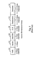
- a generic format illustrative of the x86 instruction set is shown in Figure 1. As illustrated in the figure, an x86 instruction consists of from one to five optional prefix bytes 102, followed by an operation code (opcode) field 104, an optional addressing mode (Mod R/M) byte 106, an optional scale-index-base (SIB) byte 108, an optional displacement field 110, and an optional immediate data field 112.
- the opcode field 104 defines the basic operation for a particular instruction.
- the default operation of a particular opcode may be modified by one or more prefix bytes.
- a prefix byte may be used to change the address or operand size for an instruction, to override the default segment used in memory addressing, or to instruct the processor to repeat a string operation a number of times.
- the opcode field 104 follows the prefix bytes 102, if any, and may be one or two bytes in length.
- the addressing mode (Mod R/M) byte 106 specifies the registers used as well as memory addressing modes.
- the scale-index-base (SIB) byte 108 is used only in 32-bit base-relative addressing using scale and index factors,
- a base field of the SIB byte specifies which register contains the base value for the address calculation, and an index field specifies which register contains the index value.
- a scale field specifies the power of two by which the index value will be multiplied before being added, along with any displacement, to the base value.
- the next instruction field is the optional displacement field 110, which may be from one to four bytes in length.
- the displacement field 110 contains a constant used in address calculations.
- the optional immediate field 112 which may also be from one to four bytes in length, contains a constant used as an instruction operand.
- the shortest x86 instructions are only one byte long, and comprise a single opcode byte.
- the 80286 sets a maximum length for an instruction at 10 bytes, while the 80386 and 80486 both allow instruction lengths of up to 15 bytes.
- the complexity of the x86 instruction set poses difficulties in implementing high performance x86 compatible superscalar microprocessors.
- One difficulty arises from the fact that instructions must be scanned and aligned with respect to the parallel-coupled instruction decoders of such processors before proper decode can be effectuated.
- the x86 instruction set consists of variable byte length instructions, the start bytes of successive instructions within a line are not necessarily equally spaced, and the number of instructions per line is not fixed.
- EP-A-0 651 322 discloses an instruction cache for a superscalar processor where the instructions have variable length formats as in the case of the x86 microprocessor instruction set It discloses a solution in which instructions are prefetched and predecoded, and bits indicative among other things of the start and end of each instruction are encoded with the instructions in the instruction cache.
- the problems outlined above are in large part solved by an instruction scanning unit in accordance with the present invention.
- the instruction scanning unit processes start and end byte information associated with a plurality of contiguous instruction bytes.
- the present invention provides an instruction scanning unit for scanning a block of predecode information associated with a plurality of contiguous instruction bytes wherein said block of predecode information includes start byte information indicative of bytes which start instructions and wherein said block of predecode information further includes end byte information indicative of bytes which end instructions, said instruction scanning unit comprising: an input bus configured to convey said block of predecode information; characterized by:
- the present invention also provides method of identifying valid instructions within a plurality of instruction bytes comprising:
- the processing of start byte information and end byte information is performed independently and in parallel, and the instruction scanning unit produces a plurality of scan values.
- the scan values identify valid instructions within the plurality of contiguous instruction bytes. Since the start and end byte information is processed in parallel, the instruction scanning unit may be implemented in a relatively small number of cascaded logic levels. Therefore, the instruction scanning unit may be advantageously employed in high frequency superscalar microprocessors. Furthermore, performance of the superscalar microprocessor may be advantageously increased since multiple instructions are identified in a given clock cycle and therefore may be dispatched and executed concurrently.
- the instruction scanning unit is scalable. Multiple instruction scanning units may be advantageously operated in parallel to process a larger plurality of contiguous instruction bytes. A larger number of instructions may be identified per clock cycle, allowing for a higher performance superscalar microprocessor. Particularly, instructions which overflow from a prior instruction scanning unit are detected as well as instructions which overflow to a subsequent instruction scanning unit.
- the scalability functions may also be used by external logic to gather portions of instructions from one clock cycle for use in the subsequent clock cycle when a single instruction scanning unit is employed or when an overflow occurs from the last instruction scanning unit.
- the instruction scanning unit detects certain error conditions.
- start and end byte information is examined for at least two error conditions.
- the instruction scanning unit for scanning a block of predecode information associated with a plurality of contiguous instruction bytes.
- the block of predecode information includes start byte information indicative of bytes which start instructions as well as end byte information indicative of bytes which end instructions.
- the instruction scanning unit comprises an input bus, a first subunit, and a second subunit Coupled to both the first and the second subunits is the input bus, which is configured to convey the block of predecode information.
- the first subunit is configured to receive the end byte information and to generate a plurality of instruction valid values. Each of the plurality of instruction valid values is indicative of a potential valid instruction starting at a particular byte within the plurality of contiguous instruction bytes and ending at a byte specified by the end byte information.
- the first subunit is configured to convey the plurality of instruction valid values on a plurality of instruction valid buses.
- the second subunit is configured to receive the start byte information and to generate a plurality of instruction start counts.
- Each of the instruction start counts is indicative of a number of instructions which start between a first one of the plurality of contiguous instruction bytes and a particular one of the plurality of contiguous instruction bytes.
- the second subunit is configured to convey the plurality of instruction start counts on a plurality of instruction start count buses, and the first second subunits operate in parallel.
- Figure 1 is a block diagram of a generic x86 instruction format.
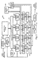
- Figure 2 is a block diagram of a superscalar microprocessor including an instruction cache.
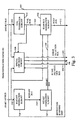
- Figure 3 is a block diagram of an instruction scanning unit included within the instruction cache of Figure 2.
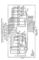
- Figure 4A is a logic diagram of portions of an IVAL generation subunit shown in Figure 3.
- Figure 4B is a logic diagram of portions of a PCSTART generation subunit shown in Figure 3.
- Figure 4C is a logic diagram of portions of an NSTART generation subunit shown in Figure 3.
- Figure 4D is a logic diagram of portions of a Scan Bus generation subunit shown in Figure 3.
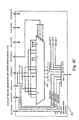
- Figure 4E is a logic diagram of portions of a Special Checking subunit shown in Figure 3.
- superscalar microprocessor 200 includes a prefetch/predecode unit 202 and a branch prediction unit 220 coupled to an instruction cache 204.
- Instruction alignment unit 206 is coupled between instruction cache 204 and a plurality of decode units 208A-208D (referred to collectively as decode units 208).
- decode units 208A-208D are coupled to respective reservation station units 210A-210D (referred to collectively as reservation stations 210), and each reservation station 210A-210D is coupled to a respective functional unit 212A-212D (referred to collectively as functional units 212).
- Decode units 208, reservation stations 210, and functional units 212 are further coupled to a reorder buffer 216, a register file 218 and a load/store unit 222.
- a data cache 224 is finally shown coupled to load/store unit 222, and an MROM unit 209 is shown coupled to instruction alignment unit 206.
- instruction cache 204 is a high speed cache memory provided to temporarily store instructions prior to their dispatch to decode units 208.
- instruction cache 204 is configured to cache up to 32 kilobytes of instruction code organized in lines of 16 bytes each (where each byte consists of 8 bits).
- instruction code is provided to instruction cache 204 by prefetching code from a main memory (not shown) through prefetch/predecode unit 202. It is noted that instruction cache 204 could be implemented in a set-associative, a fully-associative, or a direct-mapped configuration.
- Prefetch/predecode unit 202 is provided to prefetch instruction code from the main memory for storage within instruction cache 204.
- prefetch/predecode unit 202 is configured to burst 64-bit wide code from the main memory into instruction cache 204. It is understood that a variety of specific code prefetching techniques and algorithms may be employed by prefetch/predecode unit 202.
- prefetch/predecode unit 202 fetches instructions from the main memory, it generates three predecode bits associated with each byte of instruction code: a start bit, an end bit, and a "functional" bit.
- the predecode bits form tags indicative of the boundaries of each instruction.
- the predecode tags may also convey additional information such as whether a given instruction can be decoded directly by decode units 208 or whether the instruction must be executed by invoking a microcode procedure controlled by MROM unit 209, as will be described in greater detail below.
- a set of start bits conveyed with a group of contiguous instruction bytes forms start byte information for that group of contiguous instruction bytes.
- a set of end bits conveyed with a group of contiguous instruction bytes forms end byte information for that group of contiguous instruction bytes.
- Table I indicates one encoding of the predecode tags. As indicated within the table, if a given byte is the first byte of an instruction, the start bit for that byte is set. If the byte is the last byte of an instruction, the end bit for that byte is set. If a particular instruction cannot be directly decoded by the decode units 208, the functional bit associated with the first byte of the instruction is set. On the other hand, if the instruction can be directly decoded by the decode units 208, the functional bit associated with the first byte of the instruction is cleared, The functional bit for the second byte of a particular instruction is cleared if the opcode is the first byte, and is set if the opcode is the second byte.
- the first byte is a prefix byte.
- the functional bit values for instruction byte numbers 3-8 indicate whether the byte is a MODRM or an SIB byte, or whether the byte contains displacement or immediate data. Encoding of Start, End and Functional Bits Instr. Byte Number Start Bit Value End Bit Value Functional Bit Value Meaning 1 1 X 0 Fast decode 1 1 X 1 MROM instr.
- Opcode is first byte 2 0 X 1 Opcode is this byte, first byte is prefix 3-8 0 X 0 Mod R/M or SIB byte 3-8 0 X 1 Displacement or immediate data; the second functional bit set in bytes 3-8 indicates immediate data 1-8 X 0 X Not last byte of instruction 1-8 X 1 X Last byte of instruction
- certain instructions within the x86 instruction set may be directly decoded by decode unit 208. These instructions are referred to as “fast path” instructions.
- the remaining instructions of the x86 instruction set are referred to as "MROM instructions”.
- MROM instructions are executed by invoking MROM unit 209. More specifically, when an MROM instruction is encountered, MROM. unit 209 parses and serializes the instruction into a subset of defined fast path instructions to effectuate a desired operation.
- a listing of exemplary x86 instructions categorized as fast path instructions as well as a description of the manner of handling both fast path and MROM instructions will be provided further below.
- each of the decode units 208 includes decoding circuitry for decoding the predetermined fast path instructions referred to above.
- each decode unit 208A-208D routes displacement and immediate data to a corresponding reservation station unit 210A-210D.
- Output signals from the decode units 208 include bit-encoded execution instructions for the functional units 212 as well as operand address information, immediate data and/or displacement data.
- the superscalar microprocessor of Figure 2 supports out of order execution, and thus employs reorder buffer 216 to keep track of the original program sequence for register read and write operations, to implement register renaming, to allow for speculative instruction execution and branch misprediction recovery, and to facilitate precise exceptions.
- a temporary storage location within reorder buffer 216 is reserved upon decode of an instruction that involves the update of a register to thereby store speculative register states.
- Reorder buffer 216 may be implemented in a first-in-first-out configuration wherein speculative results move to the "bottom" of the buffer as they are validated and written to the register file, thus making room for new entries at the "top" of the buffer.
- reorder buffer 216 Other specific configurations of reorder buffer 216 are also possible, as will be described further below. If a branch prediction is incorrect. the results of speculatively-executed instructions along the mispredicted path can be invalidated in the buffer before they are written to register file 218.
- each reservation station unit 210A-210D is capable of holding instruction information (i.e., bit encoded execution bits as well as operand values, operand tags and/or immediate data) for up to three pending instructions awaiting issue to the corresponding functional unit. It is noted that for the embodiment of Figure 2, each decode unit 208A-208D is associated with a dedicated reservation station unit 210A-210D, and that each reservation station unit 210A-210D is similarly associated with a dedicated functional unit 212A-212D.
- decode units 208 Accordingly, four dedicated "issue positions" are formed by decode units 208, reservation station units 210 and functional units 212. Instructions aligned and dispatched to issue position 0 through decode unit 208A are passed to reservation station unit 210A and subsequently to functional unit 212A for execution. Similarly, instructions aligned and dispatched to decode unit 208B are passed to reservation station unit 210B and into functional unit 212B, and so on.
- register address information is routed to reorder buffer 216 and register file 218 simultaneously.
- the x86 register file includes eight 32 bit real registers (i.e., typically referred to as EAX, EBX, ECX, EDX, EBP, ESI, EDI and ESP).
- Reorder buffer 216 contains temporary storage locations for results which change the contents of these registers to thereby allow out of order execution.
- a temporary storage location of reorder buffer 216 is reserved for each instruction which, upon decode, is determined to modify the contents of one of the real registers.
- reorder buffer 216 may have one or more locations which contain the speculatively executed contents of a given register. If following decode of a given instruction it is determined that reorder buffer 216 has a previous location or locations assigned to a register used as an operand in the given instruction, the reorder buffer 216 forwards to the corresponding reservation station either: 1) the value in the most recently assigned location, or 2) a tag for the most recently assigned location if the value has not yet been produced by the functional unit that will eventually execute the previous instruction. If the reorder buffer has a location reserved for a given register, the operand value (or tag) is provided from reorder buffer 216 rather than from register file 218. If there is no location reserved for a required register in reorder buffer 216, the value is taken directly from register file 218. If the operand corresponds to a memory location, the operand value is provided to the reservation station unit through load/store unit 222.
- Reservation station units 210A-210D are provided to temporarily store instruction information to be speculatively executed by the corresponding functional units 212A-212D. As stated previously, each reservation station unit 210A-210D may store instruction information for up to three pending instructions. Each of the four reservation stations 210A-210D contain locations to store bit-encoded execution instructions to be speculatively executed by the corresponding functional unit and the values of operands. If a particular operand is not available, a tag for that operand is provided from reorder buffer 216 and is stored within the corresponding reservation station until the result has been generated (i.e., by completion of the execution of a previous instruction).
- Reorder buffer 216 ensures that data coherency is maintained in situations where read-after-write dependencies occur.
- each of the functional units 212 is configured to perform integer arithmetic operations of addition and subtraction, as well as shifts, rotates, logical operations, and branch operations. It is noted that a floating point unit (not shown) may also be employed to accommodate floating point operations.
- Each of the functional units 212 also provides information regarding the execution of conditional branch instructions to the branch prediction unit 220. If a branch prediction was incorrect, branch prediction unit 220 flushes instructions subsequent to the mispredicted branch that have entered the instruction processing pipeline, and causes prefetch/predecode unit 202 to fetch the required instructions from instruction cache 204 or main memory. It is noted that in such situations. results of instructions in the original program sequence which occur after the mispredicted branch instruction are discarded, including those which were speculatively executed and temporarily stored in load/store unit 222 and reorder buffer 216. Exemplary configurations of suitable branch prediction mechanisms are well known.
- Results produced by functional units 212 are sent to the reorder buffer 216 if a register value is being updated, and to the load/store unit 222 if the contents of a memory location is changed. If the result is to be stored in a register, the reorder buffer 216 stores the result in the location reserved for the value of the register when the instruction was decoded. As stated previously, results are also broadcast to reservation station units 210A-210D where pending instructions may be waiting for the results of previous instruction executions to obtain the required operand values.
- load/store unit 222 provides an interface between functional units 212A-212D and data cache 224.
- load/store unit 222 is configured with a load/store buffer with eight storage locations for data and address information for pending loads or stores.
- Decode units 208 arbitrate for access to the load/store unit 222. When the buffer is full, a decode unit must wait until the load/store unit 222 has room for the pending load or store request information The load/store unit 222 also performs dependency checking for load instructions against pending store instructions to ensure that data coherency is maintained.
- Data cache 224 is a high speed cache memory provided to temporarily store data being transferred between load/store unit 222 and the main memory subsystem.
- data cache 224 has a capacity of storing up to eight kilobytes of data. It is understood that data cache 224 may be implemented in a variety of specific memory configurations, including a set associative configuration.
- Instruction scanning unit 300 receives a start bit bus 302 and an end bit bus 304 from instruction cache 204, and produces a SCAN0 previous line bus 306, a scan overflow bus 308, an error detection bus 310, and a scan bus 312. SCAN0 previous line bus 306, scan overflow bus 308, error detection bus 310, and scan bus 312 are coupled to instruction alignment unit 206. Instruction scanning unit 300 is configured with several subunits which perform various tasks. An IVAL generation subunit 314 is coupled to end bit bus 304 and to an IVAL bus 324. A PCSTART generation subunit 316 is included, coupled to start bit bus 302 and a PCSTART bus 318.
- NSTART bus 320 is further coupled to a scan bus generation subunit 326 and to a special checking subunit 328. Further coupled to scan bus generation subunit 326 is start bit bus 302 and IVAL bus 324. Coupled to special checking subunit 328 are start bit bus 302, end bit bus 304. SCAN0 previous line bus 306, scan overflow bus 308, error detection bus 310, and IVAL bus 324.
- instruction scanning unit 300 is configured to scan start byte information and end byte information associated with a plurality of contiguous instruction bytes.
- the start byte information is conveyed on start bit bus 302 and the end byte information is conveyed on end bit bus 304.
- Start bit bus 302 and end bit bus 304 together form an input bus to instruction scanning unit 300.
- instruction scanning unit 300 produces a set of scan values on scan bus 312 which are indicative of the boundaries of instructions within the plurality of contiguous instruction bytes.
- start and end byte information is conveyed for eight contiguous instruction bytes.
- Instruction scanning unit 300 scans the start byte information independently and in parallel with the end byte information in PCSTART generation subunit 316, NSTART generation subunit 322, and IVAL generation subunit 314. The information so generated is combined in scan bus generation subunit 326, producing a set of masks on scan bus 312.
- a mask is a field of bits, each bit being associated with one instruction byte within the plurality of contiguous instruction bytes being scanned. If a particular bit of a mask is set, the associated byte is a portion of the instruction identified by that mask. If a particular bit of a mask is clear, the associated byte is not a portion of the instruction identified by that mask.
- Each mask identifies instruction bytes which form a valid instruction.
- scan bus 312 conveys four eight-bit masks identifying the first four valid instructions found within the eight bytes associated with the start and end byte information conveyed to instruction scanning unit 300.
- the masks produced on scan bus 312 are conveyed to instruction alignment unit 206, along with information on SCAN0 previous line bus 306, scan overflow bus 308, error detection bus 310, for use in locating valid instruction bytes from a plurality of instructions associated with the start and end byte information processed by instruction scanning unit 300.
- Special checking subunit 328 is included to generate error information associated with start and end byte information as well as to provide scalability functionality.
- Scalability functionality is functionality that allows multiple instruction scanning units similar to instruction scanning unit 300 to operate simultaneously on a larger plurality of contiguous instruction bytes.
- the scalability functionality of special checking subunit 328 includes detecting that an instruction ends in the eight bytes being scanned but does not begin in that eight bytes, and detecting that an instruction begins in the eight bytes being scanned by does not end in that eight bytes.
- IVAL generation subunit 314 receives end byte information associated with a plurality of contiguous instruction bytes. IVAL generation subunit 314 generates an instruction valid value associated with each byte in the plurality of contiguous instruction bytes. Instruction valid values are values which identify bytes which may form a valid instruction. In one embodiment, the instruction valid values generated by IVAL generation subunit 314 are masks as described above. Each instruction valid value generated by IVAL generation subunit 314 identifies a potentially valid instruction beginning at the associated byte within the contiguous instruction bytes being scanned. The potentially valid instruction ends at the byte associated with the first end bit encountered in the associated end byte information subsequent to the byte position of the associated byte.
- the end bit corresponding to the associated byte is included in determining the end of the potentially valid instruction. Since the start byte information is not available to IVAL generation subunit 314, an instruction valid value is generated for each byte being scanned as if that byte were a start byte. Therefore, the instruction valid values identify potentially valid instructions. The correct instruction valid values may then be selected from this set of instruction valid values according to the start byte information, as will be described below.
- PCSTART generation subunit 316 and NSTART generation subunit 322 are a pair of subunits which generate an instruction start count for each byte being scanned.
- the instruction start count for a particular byte indicates the number of instructions which start within the eight bytes being scanned but prior to the particular byte. This information, along with the start byte information, may be used to determine which of the instruction valid values generated from IVAL generation subunit 314 are the correct instruction valid values.
- PCSTART generation subunit 316 generates intermediate instruction start counts according to a set of scan regions within the plurality of contiguous instruction bytes being scanned. In one embodiment, four scan regions are used. The first scan region comprises the first byte of the contiguous instruction bytes being scanned. The second scan region includes the second through fourth bytes, while the third scan region includes the fifth through seventh bytes. Finally, the fourth scan region comprises the eighth byte being scanned. For a particular byte within the contiguous bytes being scanned, the associated intermediate instruction start count indicates the number of instructions which start prior to that particular byte but within the scan region that includes the particular byte.
- an instruction which starts in the last byte of the scan region prior to the scan region that includes the particular byte is included in the associated intermediate instruction start count.
- the logic gates embodying the function may be advantageously limited to a relatively small number of inputs while still utilizing a parallel scanning technique, as will be explained in more detail below.
- the intermediate instruction start counts are decoded counts such that a bit set in one position of the count indicates zero prior start bytes; a bit set in another position of the count indicates one prior start byte; etc. These intermediate instruction start counts are conveyed on PCSTART bus 318 to NSTART generation subunit 322.
- NSTART generation subunit 322 accepts the intermediate instruction start counts generated by PCSTART generation subunit 316 and generates the instruction start counts mentioned above.
- a particular instruction start count is generated by shifting the instruction start count of the last byte of the previous scan region by the intermediate instruction start count associated with a particular byte of the current scan region. Since the intermediate instruction start count values and the instruction start count values are decoded, the shifting adds the intermediate instruction start count of each byte to the instruction start count of the last byte of the previous scan region. In this manner, the correct instruction start count for each byte may be generated.
- the instruction start counts and intermediate instruction start counts convey a value between zero and three. Furthermore, a value may be conveyed indicative of four or more instruction starts.
- NSTART generation subunit 322 conveys the instruction start counts to scan bus generation subunit 326 on NSTART bus 320.
- Scan bus generation subunit 326 selects a plurality of scan bus values from the instruction valid values conveyed on IVAL bus 324.
- the plurality of scan bus values are conveyed on scan bus 312.
- up to four scan bus values are selected corresponding to the first four valid instructions contained within the plurality of contiguous instruction bytes being scanned.
- a particular instruction valid value is selected by scan bus generation subunit 326 if the start byte information indicates that the associated byte is a start byte and the instruction start count associated with that byte is between zero and three.
- the first scan value conveys the instruction valid value associated with an instruction start count of zero.
- the first scan value identifies a valid instruction associated with the first start byte within the plurality of contiguous instruction bytes being scanned (i.e. the first valid instruction within the plurality of contiguous instruction bytes).
- the second, third, and fourth scan values similarly identify the second, third, and fourth valid instructions within the plurality of contiguous instruction bytes being scanned, if that many valid instructions may be located.
- Instruction scanning unit 300 is a parallel instruction scanning unit which (as will be shown below) may be implemented in relatively few cascaded levels of logic.
- an instruction scanning unit identifies multiple valid instructions per clock cycle and may allow a short clock cycle design.
- special checking subunit 328 provides the aforementioned error checking and scalability functionality.
- special checking subunit checks for two types of errors. First, between each two bytes indicated as start bytes, one end byte should exist. Special checking subunit 328 detects two successive start bytes without an intervening end byte. Furthermore, each byte which is indicated as the end of an instruction should be immediately followed by a start byte. Special checking subunit 328 also ensures that this relationship is true for each end byte within the plurality of contiguous instruction bytes being scanned. Exemplary logic circuits for providing these checks will be described below with respect to Figure 4E.
- special checking subunit 328 provides scalability functionality. If several instruction scanning units 300 were to be used in parallel to process a larger number of contiguous instruction bytes, then instructions may have some bytes scanned by one instruction scanning unit and other bytes scanned by another instruction scanning unit. This may happen if an instruction begins in the plurality of contiguous bytes scanned by one instruction scanning unit and ends in the plurality of contiguous bytes scanned by another instruction scanning unit.
- the instruction scanning unit detects instructions which begin in the plurality of contiguous instruction bytes being scanned but which do not end within the plurality of contiguous instruction bytes being scanned. If such a condition is detected, a signal associated with the scan bus value for which the condition is detected is asserted on scan overflow bus 308.
- scan overflow bus 308 includes a signal associated with each scan value conveyed on scan bus 312.
- instruction scanning unit 300 detects instructions which end in the plurality of contiguous instruction bytes currently being scanned but do not begin in these bytes. This detection is provided by detecting whether or not the first byte of the plurality of contiguous bytes is the start of an instruction. If it is the start of an instruction, then no instruction that ends in the current line begins in the previous line. If it is not the start of an instruction and no error condition is detected, then the bytes up to the first end byte are the end of an instruction which begins in a previous plurality of contiguous bytes.
- the instruction valid value indicative of these bytes is conveyed on the overflow portion of scan bus 312.
- the overflow detection is conveyed on SCAN0 previous line bus 306.
- special checking subunit 328 allows a number of instruction scanning units to be used in parallel.
- Each instruction scanning unit indicates when an instruction overflows to the next instruction scanning unit and provides an instruction valid value indicative of the bytes within its plurality of contiguous bytes that form a portion of the overflowing instruction.
- the subsequent instruction scanning unit indicates that an instruction has overflowed from the previous unit and provides an instruction valid value on the overflow portion of scan bus 312 (as noted above) which is indicative of the bytes which form the remainder of the overflowing instruction.
- This information could be advantageously used to form the identified instruction.
- these values may be used by circuits outside of instruction scanning unit 300 to capture the first portion of an overflowing instruction. The remainder of the overflowing instruction would be indicated by the instruction scanning unit in the following cycle, and the external logic could then form the overflowing instruction from the two sets of bytes.
- instruction scanning unit 300 may be further illuminated through the use of an example.
- the example will be presented for the embodiment of instruction scanning unit 300 that scans eight contiguous instruction bytes and provides up to four scan bus values per clock cycle. Therefore, this embodiment generates eight instruction valid values on IVAL bus 324 (one for each of the eight instruction bytes). These buses will be labeled IVAL0, IVAL1, IVAL2, IVAL3. IVAL4, IVAL5, IVAL6,IVAL7, and IVAL8. Also, the four scan regions described above will be processed by PCSTART generation subunit 316. The values of the intermediate instruction start counts will be conveyed on PCSTART0, PCSTART1, PCSTART2, PCSTART3, PCSTART4, PCSTART5, PCSTART6, and PCSTART7.
- Each value includes four bits which indicate the number of start bytes prior to the current byte. If bit 0 is set, there are zero start bytes prior to the current byte. If bit 1 is set, there is one start byte prior to the current byte. If bit 2 is set, there are two start bytes prior to the current byte, If bit 3 is set there are three start bytes prior to the current byte. If no bits are set, there are four or more start bytes prior to the current byte.
- the instruction start counts generated by NSTART generation subunit 322 are conveyed on NSTART0, NSTART1, NSTART2, NSTART3, NSTART4, NSTART5, NSTART6, and NSTART7.
- the scan bus values are conveyed on SCAN0, SCAN1, SCAN2, and SCAN3.
- the number indicates the associated byte. Therefore, IVAL0, PCSTART0, and NSTART0 are associated with the first of the eight contiguous instruction bytes (i.e. byte 0). Similarly, IVAL1, PCSTART1, and NSTART1 are associated with the second of the eight contiguous instruction bytes (i.e. byte 1), etc.
- SCAN0 is the scan value indicating the first valid instruction within the eight contiguous instruction bytes. Similarly, SCAN1 is the scan value indicating the second valid instruction within the eight contiguous instruction bytes, etc.
- the start byte and end byte information indicates the following values: Byte position 01234567 Start byte information 10001110 End byte information 00011101
- the start byte information and end byte information comprises a bit for each byte. If the bit is set, the corresponding byte is a start (or end) byte. If the bit is clear, the corresponding byte is not a start (or an end) byte. Therefore, for this example the first valid instruction begins at byte 0 and ends at byte 3. The second valid instruction begins and ends at byte 4 (therefore, the second valid instruction is a single byte). Similarly, the third valid instruction begins and ends at byte 5. Finally, the fourth valid instruction begins at byte 6 and ends at byte 7. The correct scan bus values for this example would be:
- IVAL generation subunit 314 When the aforementioned start and end byte values are conveyed to instruction scanning unit 300, IVAL generation subunit 314 generates eight instruction valid values as described above. IVAL0 generates binary ones beginning in byte 0 and ending at the occurrence of the next end bit, which is at byte 3. IVAL1 generates binary ones beginning at byte 1 and ending at the occurrence of the next end bit, again at byte 3. IVAL4 generates binary ones beginning at byte 4 and ending at the occurrence of the next end bit (now at byte 4). A list of the generated instruction valid values is shown below.
- PCSTART generation subunit 316 generates intermediate start counts according to the scan regions defined above. Therefore, PCSTART0 contains a zero start count since no bytes precede PCSTART0. PCSTART3, however, contains a count of one since PCSTART0 is a start byte, it is the last byte of the previous scan region, and no other start bits occur in the current scan region. PCSTART5 contains a count of one as well, since byte position three (the last byte position of the second scan region) is not a start bit and one start bit exists in third scan region prior to byte five (i.e. byte 4). The values for the intermediate instruction start counts are shown below for this example:
- NSTART generation subunit 322 receives the intermediate instruction start counts and generates the instruction start counts. Since the counts for the first and second scan regions already contain information about each start byte prior to the associated position (the counts in the second scan region include the last and only byte of the first scan region), these counts are unchanged by NSTART generation subunit 322.
- the intermediate instruction counts in the third region i.e. PCSTART4, PCSTART5, and PCSTART6 provide shift amounts for the count in PCSTART3.
- PCSTART3 contains a count of one, PCSTART4 a count of zero, PCSTART5 a count of one, and PCSTART6 a count of two. Therefore, NSTART4 conveys PCSTART3 shifted by zero (i.e.
- NSTART5 conveys PCSTART3 shifted by one (i.e. two)
- NSTART6 conveys PCSTART3 shifted by two (i.e. three).
- NSTART7 conveys NSTART6 shifted by two (the amount on PCSTART7). This causes NSTART7 to convey a value of 4 binary zeros, indicative of four or more start bits prior to byte 7.
- the values for each instruction start count are shown below for this example:
- Scan bus generation subunit 312 receives the NSTART and IVAL values shown above as its instruction start counts and instruction valid values along with the original start byte information, as noted above. Scan bus generation subunit 312 then generates its four scan values from the received values. Since byte zero is a start byte and its associated instruction start count (NSTART0) is zero, the instruction valid value associated with byte zero (IVAL0) is selected as SCAN0. Byte four is also a start byte, and its associated instruction start count (NSTART4) is one. Therefore, the instruction valid value associated with byte four (IVAL4) is selected as SCAN1. Similarly, IVAL5 and IVAL6 are selected as SCAN2 and SCAN3, respectively. Therefore, the final scan values are shown below and equal the expected results for the example:
- the instruction valid values generated by IVAL generation subunit 314 with this example of end byte information are:
- the intermediate instruction start counts generated by PCSTART generation subunit 316 according to this example's start byte information are:
- SCAN0 is selected to be IVAL0.
- Byte 3 is a start byte and NSTART3 indicates one previous start byte, so SCAN1 is selected to be IVAL3. There are no other start bits, so SCAN2 and SCAN3 are selected to be zero.
- Figure 4A shows an exemplary rogic diagram or a portion of IVAL generation subunit 314.
- IVAL0 is a portion of IVAL bus 324 conveying the instruction valid value associated with the first of the eight contiguous instruction bytes
- IVAL1 is a portion of IVAL bus 324 conveying the instruction valid value associated with the second of the eight contiguous instruction bytes.
- Other logic circuits (not shown) generate the instruction valid values associated with the other instruction bytes.
- the instruction valid values for these bytes are conveyed on IVAL2 through IVAL7.
- the values conveyed on IVAL0 through IVAL7 form IVAL bus 324, as shown in Figure 4A.
- End bit bus 304 is shown as eight conductors 304A-304H in Figure 4A, indicative of the eight contiguous instruction bytes scanned by this embodiment of instruction scanning unit 300.
- Conductor 304A conveys the end bit for the first of the eight contiguous instruction bytes (referred to as byte 0)
- conductor 304B conveys the end bit for the second of the eight contiguous instruction bytes (referred to as byte 1), etc.
- An examination of the exemplary circuits shows that a particular bit for an instruction valid value is generated as the logical NOR of the end bits between the byte associated with the instruction valid value and the byte prior to the byte associated with the particular bit, inclusive. Therefore, the first bit of IVAL0 is a constant one (since there are no end bits to examine).
- the second bit of IVAL0 is the inverted end bit for byte 0 (i.e. the logical NOR of a single bit is an inversion).
- the third bit of IVAL0 is the NOR of the end bits for bytes 0 and 1, etc.
- Inverter 400 provides the second bit of IVAL0, and NOR gate 401 provides the third bit of IVAL0.
- the NOR function for the fourth bit of IVAL0 is provided by NOR gate 402, while NOR gate 402, inverter 403, and AND gate 405 provide the NOR function for the fifth bit of IVAL0.
- the sixth bit of IVAL0 is generated from NOR gate 402, NOR gate 404, and AND gate 408.
- the seventh bit of IVAL0 is generated by NOR gate 402, NOR gate 406, and AND gate 409
- the eighth bit of IVAL0 is provided by NOR gate 402, NOR gate 406, inverter 407 and AND gate 410.
- the third bit of IVAL1 is the inverted end bit for byte 1. Note that the first bit (a constant zero) is not shown in Figure 4A, and the second bit is a constant one.
- the fourth bit of IVALI is the NOR of the end bit for bytes 1 and 2, etc. In this way, the first end bit that is detected following the associated byte causes the subsequent bits in the instruction valid value to be cleared. Bits between the associated byte and the first end bit are set.
- Exemplary logic circuits for generating IVAL1 are shown in Figure 4A.
- the first bit of IVAL1 is not shown, since it is a constant zero.
- the second bit is a constant one.
- Inverter 411 provides the third bit of IVAL1, while the fourth bit is provided by NOR gate 412.
- the fifth bit of IVAL1 is generated by NOR gate 413.
- the sixth bit of IVAL1 is generated by NOR gate 413, inverter 414, and AND gate 417.
- NOR gate 413, NOR gate 415, and AND gate 418 combine to form the NOR function for the seventh bit of IVAL1.
- NOR gate 413, NOR gate 416, and AND gate 419 form the NOR function for the eighth bit of IVAL1.
- IVAL generation subunit 314 shown in Figure 4A employs eight bits of information forming IVAL0 but seven bits of information forming IVAL1.
- IVAL2 is comprised of six bits, IVAL3 of five bits, etc. This is because the bits representing bytes prior to the byte position for which the instruction valid value is generated are constant zeros and therefore may be omitted.
- PCSTART generation subunit 316 receives start bit bus 302 from instruction cache 204.
- Start bit bus 302 is shown in Figure 4B as eight separate conductors which convey the eight start bits associated with the contiguous instruction bytes being scanned.
- Conductor 302A conveys the start bit associated with the first of the contiguous bytes (referred to as byte 0)
- conductor 302B conveys the start bit associated with the second of the contiguous bytes (referred to as byte 1), etc.
- Figure 4B shows exemplary logic circuits for generating PCSTART3 and PCSTART5.
- PCSTART3 is the intermediate instruction start count for byte 3 (i.e. the fourth byte) of the eight contiguous bytes.
- PCSTART5 is the intermediate instruction start count for byte 5 (i.e. the sixth byte) of the eight contiguous bytes. Since PCSTART3 and PCSTART5 are in different scan regions, the portions of end bit bus 302 on which they operate are separate.
- Other logic circuits (not shown) generate intermediate instruction start counts for other bytes within the contiguous instruction bytes scanned by instruction scanning unit 300.
- the term "previous start bit” refers to a start bit within the scan region associated with a particular intermediate instruction start count and to the start bit associated with the last byte of the previous scan region.
- each intermediate instruction byte count and each instruction byte count are decoded values.
- the first bit when set, indicates that zero start bytes exist prior to the current byte.
- the second bit when set, indicates that one start byte exists prior to the current byte, etc. Therefore, for intermediate start count generation, the first bit is set if none of the previous start bits are set. This is a NOR function of the associated previous start bits, and is shown as NOR gate 430 for PCSTART3 and NOR gate 431 for PCSTART5.
- the second bit of an intermediate instruction start count indicates one previous start bit is set. Therefore, an AND/OR network may provide the value where each of the input terminals of the AND gate are inverted except for one. In this manner, if one and only one previous start bit is set, then the resulting intermediate instruction start count bit will be set.
- This function is provided by AND gate 432, AND gate 433, AND gate 434, and OR gate 435 for PCSTART3.
- AND gate 436, AND gate 437, and OR gate 438 provide a similar function for PCSTART5 generation.
- Two previous start bits being set is indicated by setting bit two of the intermediate instruction start counts.
- An AND/OR network similar to the network for bit 1 may provide the value, except that two of the input terminals of the AND gates are not inverted. In this manner, if any two previous start bits are set but no more than two are set, then the resulting intermediate instruction start count bit will be set.
- AND gate 439, AND gate 440, AND gate 441, and OR gate 442 provide this function for the embodiment shown in Figure 4B for PCSTART3.
- AND gate 443 provides the function for PCSTART5.
- PCSTART5 can not have three previous start bits set in this embodiment.
- PCSTART5 has bits 3 and 4 of start bit bus 302 as its previous start bits, and so the largest number of previous start bits is two. Therefore, bit three of PCSTART5 is set to a constant zero.
- NSTART4 The generation of the instruction start count associated with byte four (i.e. the fifth byte) of the plurality of contiguous instruction bytes scanned by instruction scanning unit 300 is depicted (referred to as NSTART4).
- NSTART4 the instruction start counts for the first two scan regions are unmodified from the intermediate instruction start counts. These unmodified counts are shown in Figure 4C as buses 450, 451, 452, and 453, respectively.
- NSTART4 is PCSTART3 shifted by the value generated on PCSTART4.
- Multiplexor 454 is configured to provide this shifting.
- Ports 2 and 3 of multiplexor 454 are operated similarly with respect to the third and fourth bits of PCSTART4. Circuits for generating NSTART5, NSTART6, and NSTART7 are configured similarly.
- FIG. 4D exemplary logic circuits for a portion of one embodiment of scan bus generation subunit 326 are depicted.
- logic circuits suitable for generating the first scan bus value (SCAN0) are shown.
- Multiplexor 460 is coupled to each instruction valid value generated by IVAL generation subunit 314.
- the corresponding start bits are received from instruction cache 204 on start bit bus 302, and the corresponding instruction start counts are received on NSTART bus 320.
- an instruction valid value is selected as SCAN0 if the corresponding start bit on start bit bus 302 is set and the corresponding instruction start count indicates that there are no previous instruction starts found within the plurality of contiguous instruction bytes scanned by instruction scanning unit 300. Therefore, an AND function of the corresponding start bit and the first bit of the corresponding instruction start count provides each select signal for multiplexor 460. AND network 461 provides the select signals for each port of multiplexor 460. Similar networks may be used to AND the start bits and the corresponding second bits of instruction start counts to select the instruction valid value for the second scan bus value (SCAN1). Furthermore, similar networks may form the selects for multiplexors selecting SCAN2 and SCAN3. SCAN0, SCAN 1, SCAN2, and SCAN3 are conveyed on scan bus 312 along with the value conveyed as IVAL0 (which is used for the an instruction overflowing from a previous plurality of contiguous instruction bytes).
- SCAN0 previous line bus 306 is indicative of an instruction which ends in the plurality of contiguous instruction bytes scanned by instruction scanning unit 300 but does not start in these bytes. This situation is detected by noting that an instruction does not start at the first byte of the bytes being scanned.
- error detection bus 310 This bus conveys signals indicative of an error associated with the start and end information provided on start bit bus 302 and end bit bus 304.
- a first set of signals on error detection. bus 310 indicates that an end byte is detected for a byte within the bytes being scanned and the subsequent byte is not indicated as a start byte.
- AND gate 471 provides this check for the case where byte 0 is an end byte and byte I is not a start byte. Similar logic circuits may provide this check for other bytes. These signals may be advantageously used by external logic circuits (not shown) to detect which bytes within the plurality of contiguous bytes being scanned should be retumed to predecode unit 202.
- a second set of signals on error detection bus 310 are indicative of more than one start byte being indicated before an end byte is indicated.
- This encoding is an error since the encoding indicates a new instruction is starting before the previous instruction ends.
- OR gate 472 and AND gate 473 provide this functionality for checking start bytes associated with bytes 4 and 5 of the instruction bytes being scanned when byte 3 is a start byte and bytes 4 and 5 are prior to an end bit (as indicated by bit 5 of IVAL3). If bit 5 of IVAL3 is set, then no end bytes exist between byte 3 and byte 4. Therefore, if byte 4 or byte 5 is a start byte, an error condition exists. Similar circuits may provide this check for other combinations of start and end byte information.
- special checking subunit 328 As shown in Figure 4E are exemplary logic circuits for detecting an instruction overflowing to a subsequent plurality of contiguous instruction bytes. For example, if byte seven is a start byte and is not an end byte, then the instruction starting at byte seven overflows to the subsequent plurality of instruction bytes. If the instruction associated with byte seven is selected as the first scan bus value (as indicated by the associated instruction start count), then the associated scan overflow bus signal should be asserted.
- AND gate 474 provides this functionality, and OR gate 475 allows similar gates to provide a similar check for the other instruction bytes. Similar AND and OR gates may be used for the second, third, and fourth scan bus values. It is noted that for other instruction bytes, a NOR function of the end byte information between that instruction byte and the seventh instruction byte may be performed prior to AND gate 474.
- Figures 4A-4E have used a standard symbol for combining bus conductors into a single bus or for splitting bus conductors from a single bus.
- horizontal line 476 of Figure 4E is an indication that eight NSTART buses (NSTART0-NSTART7) form NSTART bus 322.
- NSTART0-NSTART7 eight NSTART buses
- NSTART3 eight NSTART buses
- instruction scanning unit 300 which scans eight contiguous instruction bytes for up to four instructions. Other embodiments may vary the number of contiguous instruction bytes as well as the maximum number of instructions scanned for.
- Figures 4A through 4E and the RTL description are also exemplary embodiments of instruction scanning unit 300. Many other embodiments are possible and specifically contemplated.
- the instruction scanning unit unlizes two gate delays and three multiplexor delays to perform the scanning function, which may allow high frequency operation while advantageously locating multiple instructions in a single cycle. Both performance and frequency may be increased for a superscalar microprocessor implementing a similar instruction scanning unit.
Landscapes
- Engineering & Computer Science (AREA)
- Theoretical Computer Science (AREA)
- Software Systems (AREA)
- Physics & Mathematics (AREA)
- General Engineering & Computer Science (AREA)
- General Physics & Mathematics (AREA)
- Quality & Reliability (AREA)
- Advance Control (AREA)
Claims (29)
- Befehlsabfrageeinheit zum Abfragen eines Blocks von vordecodierten Informationen, die mit mehreren zusammenhängenden Befehlsbytes verbunden sind, wobei der Block von vordecodierten Informationen Startbyteinformationen enthält, die Bytes angeben, welche Befehle starten, und wobei der Block von vordecodierten Informationen ferner Endbyteinformationen enthält, die Bytes angeben, welche Befehle beenden, wobei die Befehlsabfrageeinheit aufweist:einen Eingangsbus (302, 304), der zum Übertragen des Blocks vordecodierter Informationen ausgebildet ist, wobei die Befehlsabfrageeinheit gekennzeichnet ist durch:eine erste Untereinheit (314), die mit dem Eingangsbus gekoppelt ist, wobei die erste Untereinheit zum Empfangen der Endbyteinformationen ausgebildet ist, und wobei die erste Untereinheit zum Erzeugen mehrerer Gültig-Befehlswerte ausgebildet ist, und wobei jeder der mehreren Gültig-Befehlswerte einen potentiellen gültigen Befehl angibt, der an einem bestimmten Byte innerhalb der mehreren zusammenhängenden Befehlsbytes beginnt und an einem Byte endet, das durch die Endbyteinformationen spezifiziert ist, und wobei die erste Untereinheit zum Übertragen der mehreren Gültig-Befehlswerte auf mehreren Gültig-Befehisbussen (324) ausgebildet ist; undeine zweite Untereinheit (316, 322), die mit dem Eingangsbus gekoppelt ist, wobei die zweite Untereinheit zum Empfangen der Startbyteinformationen ausgebildet ist, und wobei die zweite Untereinheit zum Erzeugen mehrerer Befehlsstart-Zählungen in Reaktion auf die Startbyteinformationen ausgebildet ist, und wobei jede der mehreren Befehlsstart-Zählungen eine Anzahl von Befehlen angibt, die zwischen einem ursprünglichen der mehreren zusammenhängenden Befehlsbytes und einem bestimmten der mehreren zusammenhängenden Befehlsbytes beginnen, wobei das bestimmte der mehreren zusammenhängenden Befehlsbytes ein anderes der mehreren zusammenhängenden Befehlsbytes für jede verschiedene der mehreren Befehlsstart-Zählungen aufweist, und wobei die zweite Untereinheit zum Übertragen der mehreren Befehlsstart-Zählungen auf mehreren Befehlsstart-Zählungsbussen (320) ausgebildet ist, und wobei die erste Untereinheit und die zweite Untereinheit parallel arbeiten.
- Befehlsabfrageeinheit nach Anspruch 1, ferner mit einer dritten Untereinheit (326), die mit dem Eingangsbus, den mehreren Gültig-Befehlsbussen und den mehreren Befehlsstart-Zählungsbussen gekoppelt ist, wobei die dritte Untereinheit zum Auswählen einer Vielzahl von Abfragebuswerten aus den mehreren Gültig-Befehlswerten ausgebildet ist, und wobei die dritte Untereinheit zum Übertragen der mehreren Abfragebuswerte auf mehreren Abfragebussen (312) ausgebildet ist.
- Befehlsabfrageeinheit nach Anspruch 2, bei der die dritte Untereinheit zum Wählen der mehreren Abfragebuswerte entsprechend den Startbyteinformationen und den mehreren Befehlsstart-Zählungen ausgebildet ist.
- Befehlsabfrageeinheit nach Anspruch 3, bei der ein erste der mehreren Gültig-Befehlswerte als erster der mehreren Abfragebuswerte gewählt wird, wenn die Startbyteinformationen angeben, daß das dem ersten der mehreren Gültig-Befehlswerte zugeordnete bestimmte Byte ein Byte ist, in dem ein Befehl beginnt, und wenn eine erste der mehreren Befehlsstart-Zählungen angibt, daß null Befehle vor dem bestimmten Byte beginnen, und wobei ein zweiter der mehreren Gültig-Befehlswerte als ein zweiter der mehreren Abfragebuswerte gewählt wird, wenn die Startbyteinformationen angeben, daß das dem zweiten der mehreren Gültig-Befehiswerte zugeordnete bestimmte Byte ein Byte ist, in dem ein Befehl beginnt, und wenn eine zweite der mehreren Befehlsstart-Zählungen angibt, daß ein Befehl vor dem bestimmten Byte beginnt; und wobei ein dritter der mehreren Gültig-Befehlswerte als ein dritter der mehreren Abfragebuswerte gewählt wird, wenn die Startbyteinformationen angeben, daß das dem dritten der mehreren Gültig-Befehlswerte zugeordnete bestimmte Byte ein Byte ist, in dem ein Befehl beginnt, und wenn eine dritte der mehreren Befehlsstart-Zählungen angibt, daß zwei Befehle vor dem bestimmten Byte beginnen; und wobei ein vierter der mehreren Gültig-Befehlswerte als ein vierter der mehreren Abfragebuswerte gewählt wird, wenn die Startbyteinformationen angeben, daß das dem vierten der mehreren Gültig-Befehlswerte zugeordnete bestimmte Byte ein Byte ist, in dem ein Befehl beginnt, und wenn eine vierte der mehreren Befehlsstart-Zählungen angibt, daß drei Befehle vor dem bestimmten Byte beginnen.
- Befehlsabfrageeinheit nach Anspruch 1, bei der jeder der mehreren Gültig-Befehlswerte eine Maske aus binären Nullen und binären Einsen aufweist und die binären Einsen unmittelbar aufeinanderfolgen.
- Befehlsabfrageeinheit nach Anspruch 5, bei der die binären Einsen Bytes angeben, die den potentiellen Befehl enthalten.
- Befehlsabfrageeinheit nach Anspruch 1, bei der die zweite Untereinheit ferner zwei Untereinheiten aufweist, und wobei eine erste der beiden Untereinheiten (316) mit dem Eingangsbus gekoppelt ist, und wobei die zweite der beiden Untereinheiten (322) mit der ersten der beiden Untereinheiten und mit den mehreren Befehlsstart-Zählungsbussen gekoppelt ist.
- Befehlsabfrageeinheit nach Anspruch 7, bei der die erste der beiden Untereinheiten zum Erzeugen mehrerer Zwischen-Befehlsstart-Zählungen ausgebildet ist, wobei jede der mehreren Zwischen-Befehlsstart-Zählungen eine Anzahl von Befehlen angibt, welche zwischen einem zweiten der mehreren zusammenhängenden Befehlsbytes und einem dritten der mehreren zusammenhängenden Befehlsbytes beginnen.
- Befehlsabfrageeinheit nach Anspruch 8, bei der die zweite der beiden Untereinheiten zum Empfangen der mehreren Zwischen-Befehlsstart-Zählungen und zum Erzeugen der mehreren Befehlsstart-Zählungen ausgebildet ist.
- Befehlsabfrageeinheit nach Anspruch 9, bei der die zweite der beiden Untereinheiten zum Erzeugen einer der mehreren Befehlsstart-Zählungen durch Addieren einer der mehreren Zwischen-Befehlsstart-Zählungen zu einer anderen der Zwischen-Befehlsstart-Zählungen ausgebildet ist.
- Befehlsabfrageeinheit nach Anspruch 1, ferner mit einer vierten Untereinheit (328), die mit dem Eingangsbus gekoppelt ist, wobei die vierte Untereinheit zum Bereitstellen der Skalierbarkeitsfunktion ausgebildet ist.
- Befehlsabfrageeinheit nach Anspruch 11, bei der die Skalierbarkeitsfunktion das Erkennen eines Befehls umfaßt, der in den mehreren zusammenhängenden Befehlsbytes beginnt, jedoch nicht in den mehreren zusammenhängenden Befehlsbytes endet.
- Befehlsabfrageeinheit nach Anspruch 11, bei der die Skalierbarkeitsfunktion das Erkennen eines Befehls beinhaltet, der in den mehreren zusammenhängenden Befehlsbytes endet, jedoch nicht in den mehreren zusammenhängenden Befehlsbytes beginnt.
- Befehlsabfrageeinheit nach Anspruch 11, bei der die Skalierbarkeitsfunktion beinhaltet, zu erkennen, daß das erste derzusammenhängenden Befehlsbytes kein Startbyte ist.
- Befehlsabfrageeinheit nach Anspruch 11, bei der vierte Untereinheit ferner zum Bereitstellen einer Fehlerprüffunktion ausgebildet ist.
- Befehlsabfrageeinheit nach Anspruch 15, bei der die Fehlerprüffunktion das Erkennen eines zweiten Startbytes nach einem ersten Startbyte, jedoch vor einem Endbyte beinhaltet.
- Befehlsabfrageeinheit nach Anspruch 15, bei der die Fehlerprüffunktion beinhaltet, ein Endbyte zu erkennen, und zu erkennen, daß ein auf ein Endbyte folgendes Byte kein Startbyte ist.
- Verfahren zum Identifizieren gültiger Befehle unter mehreren Befehlsbytes mit einem zugehörigen Block von vordecodierten Informationen, wobei der Block Startbyteinformationen, die Bytes angeben, welche Befehle starten, und Endbyteinformationen enthält, die Bytes angeben, die Befehle beenden, wobei das Verfahren umfaßt:Erstellen, in Reaktion auf die Endbyteinformationen, mehrerer Gültig-Befehlswert, wobei jeder der mehreren Gültig-Befehlswerte einem jeweiligen der Befehlsbytes zugeordnet ist, und wobei jeder der mehreren Gültig-Befehlswerte einen Befehl angibt, der an dem jeweiligen einen der Befehlsbytes beginnt und an einem nachfolgenden der Befehlsbytes endet, und wobei das nachfolgende Befehlsbyte durch die Endbyteinformationen als Endbyte identifiziert wird;Erzeugen, in Reaktion auf die Bytestartinformationen, mehrerer Befehlsstart-Zählungen, wobei jede Befehlsstart-Zählung eine Anzahl von Befehlen angibt, die vor einem jeweiligen der mehreren Befehlsbytes beginnen; undWählen, in Reaktion auf die mehreren Befehlsstart-Zählungen und die Startbyteinformationen, eines der mehreren Gültig-Befehlswerte, wobei der eine der mehreren Gültig-Befehlswerte einem der mehreren Befehlsbytes entspricht, für die eine jeweilige der mehreren Befehlsstart-Zählungen gleich einem vorbestimmten Wert ist und das von den Startbyteinformationen als ein Startbyte angegeben ist.
- Verfahren nach Anspruch 18, bei dem die Endbyteinformationen mehrere Endbits aufweisen, und bei dem ein jeweiliges der mehreren Endbits dem jeweiligen der mehreren Befehlsbytes zugeordnet wird, und bei dem das gesetzte jeweilige der mehreren Endbits das jeweilige der mehreren Befehlsbytes als ein Endbyte angibt.
- Verfahren nach Anspruch 18, bei dem die Startbyteinformationen mehrere Startbits umfassen und bei dem ein jeweiliges der mehreren Startbits dem jeweiligen der mehreren Befehlsbytes zugeordnet ist, und wobei das gesetzte jeweilige der mehreren Startbits das jeweilige der mehreren Befehlsbytes als Startbyte angibt.
- Verfahren nach Anspruch 18, bei dem das Erstellen und das Erzeugen parallel durchgeführt werden.
- Verfahren nach Anspruch 18, bei dem der vorbestimmte Wert gleich null, eins, zwei oder drei ist.
- Verfahren nach Anspruch 18, ferner mit dem Übertragen des einen der mehreren Gültig-Befehlswerte an eine Befehlsabgleichseinheit, die zum Wählen von Befehlsbytes entsprechend einem Gültig-Befehlswert ausgebildet ist.
- Verfahren nach Anspruch 18, ferner mit dem Prüfen auf Fehler innerhalb der Startbyteinformationen und der Endbyteinformationen, die den mehreren Befehlsbytes zugeordnet sind.
- Verfahren nach Anspruch 24, bei dem der Prüfvorgang das Erkennen des Beginns eines zweiten Befehls im Anschluß an das Erkennen des Beginns eines ersten Befehls, jedoch vor dem Erkennen des Endes des ersten Befehls umfaßt.
- Verfahren nach Anspruch 24, bei dem das Prüfen das Erkennendes Endes eines Befehls und das Erkennen des Fehlens des Beginns eines nachfolgenden Befehls umfaßt.
- Verfahren nach Anspruch 18, ferner mit dem Erzeugen einer Skalierbarkeitsfunktion derart, daß die mehreren Befehlsbytes parallel zu einer zweiten Vielzahl von Befehlsbytes identifiziert werden können.
- Verfahren nach Anspruch 27, bei dem die Skalierbarkeitsfunktion das Erkennen eines Befehls umfaßt, der innerhalb der mehreren Befehlsbytes beginnt, jedoch nicht innerhalb der mehreren Befehlsbytes endet.
- Verfahren nach Anspruch 27, bei dem die Skalierbarkeitsfunktion das Erkennen eines Befehls umfaßt, der innerhalb der mehreren Befehlsbytes endet, jedoch nicht innerhalb der mehreren Befehlsbytes beginnt.
Applications Claiming Priority (1)
| Application Number | Priority Date | Filing Date | Title |
|---|---|---|---|
| PCT/US1996/011760 WO1998002799A1 (en) | 1996-07-16 | 1996-07-16 | A parallel and scalable instruction scanning unit |
Publications (2)
| Publication Number | Publication Date |
|---|---|
| EP0919025A1 EP0919025A1 (de) | 1999-06-02 |
| EP0919025B1 true EP0919025B1 (de) | 2001-09-26 |
Family
ID=22255462
Family Applications (1)
| Application Number | Title | Priority Date | Filing Date |
|---|---|---|---|
| EP96926083A Expired - Lifetime EP0919025B1 (de) | 1996-07-16 | 1996-07-16 | Parallele und skalierbare befehlsabtasteinheit |
Country Status (3)
| Country | Link |
|---|---|
| EP (1) | EP0919025B1 (de) |
| DE (1) | DE69615588T2 (de) |
| WO (1) | WO1998002799A1 (de) |
Families Citing this family (2)
| Publication number | Priority date | Publication date | Assignee | Title |
|---|---|---|---|---|
| KR100500002B1 (ko) * | 1996-08-27 | 2005-09-08 | 마츠시타 덴끼 산교 가부시키가이샤 | 복수의명령흐름을독립적으로처리하고,명령흐름단위로처리성능을유연하게제어하는멀티스레드프로세서 |
| CN112631660B (zh) * | 2020-12-16 | 2026-03-24 | 上海赛昉半导体科技有限公司 | 一种并行提取指令的方法与可读存储介质 |
Family Cites Families (4)
| Publication number | Priority date | Publication date | Assignee | Title |
|---|---|---|---|---|
| SG45269A1 (en) * | 1992-02-06 | 1998-01-16 | Intel Corp | End bit markers for instruction decode |
| US5689672A (en) * | 1993-10-29 | 1997-11-18 | Advanced Micro Devices, Inc. | Pre-decoded instruction cache and method therefor particularly suitable for variable byte-length instructions |
| US5559975A (en) * | 1994-06-01 | 1996-09-24 | Advanced Micro Devices, Inc. | Program counter update mechanism |
| US5758116A (en) * | 1994-09-30 | 1998-05-26 | Intel Corporation | Instruction length decoder for generating output length indicia to identity boundaries between variable length instructions |
-
1996
- 1996-07-16 EP EP96926083A patent/EP0919025B1/de not_active Expired - Lifetime
- 1996-07-16 WO PCT/US1996/011760 patent/WO1998002799A1/en not_active Ceased
- 1996-07-16 DE DE69615588T patent/DE69615588T2/de not_active Expired - Fee Related
Also Published As
| Publication number | Publication date |
|---|---|
| WO1998002799A1 (en) | 1998-01-22 |
| DE69615588T2 (de) | 2002-05-29 |
| EP0919025A1 (de) | 1999-06-02 |
| DE69615588D1 (de) | 2001-10-31 |
Similar Documents
| Publication | Publication Date | Title |
|---|---|---|
| JP3794917B2 (ja) | 分岐予測を迅速に特定するための命令キャッシュ内のバイト範囲に関連する分岐セレクタ | |
| US5758114A (en) | High speed instruction alignment unit for aligning variable byte-length instructions according to predecode information in a superscalar microprocessor | |
| US5748978A (en) | Byte queue divided into multiple subqueues for optimizing instruction selection logic | |
| US5850532A (en) | Invalid instruction scan unit for detecting invalid predecode data corresponding to instructions being fetched | |
| US6049863A (en) | Predecoding technique for indicating locations of opcode bytes in variable byte-length instructions within a superscalar microprocessor | |
| JP3803723B2 (ja) | 分岐予測を選択する分岐セレクタを採用する分岐予測機構 | |
| US6260134B1 (en) | Fixed shift amount variable length instruction stream pre-decoding for start byte determination based on prefix indicating length vector presuming potential start byte | |
| JP2002508865A (ja) | 高周波数での命令ディスパッチのための二重命令キューを用いた命令アライメントユニット | |
| US6202142B1 (en) | Microcode scan unit for scanning microcode instructions using predecode data | |
| JP3794918B2 (ja) | 復帰選択ビットを用いて分岐予測のタイプを分類する分岐予測 | |
| US5987235A (en) | Method and apparatus for predecoding variable byte length instructions for fast scanning of instructions | |
| US5852727A (en) | Instruction scanning unit for locating instructions via parallel scanning of start and end byte information | |
| US5991869A (en) | Superscalar microprocessor including a high speed instruction alignment unit | |
| US6175908B1 (en) | Variable byte-length instructions using state of function bit of second byte of plurality of instructions bytes as indicative of whether first byte is a prefix byte | |
| US5890006A (en) | Apparatus for extracting instruction specific bytes from an instruction | |
| JP2001522082A (ja) | より小さな数の分岐予測および代替ターゲットを用いて近似的により大きな数の分岐予測をすること | |
| US6061775A (en) | Apparatus and method for predicting a first microcode instruction of a cache line and using predecode instruction data to identify instruction boundaries and types | |
| EP0919025B1 (de) | Parallele und skalierbare befehlsabtasteinheit | |
| US5940602A (en) | Method and apparatus for predecoding variable byte length instructions for scanning of a number of RISC operations | |
| US5898851A (en) | Method and apparatus for five bit predecoding variable length instructions for scanning of a number of RISC operations | |
| US6134650A (en) | Apparatus and method for predicting a first scanned instruction as microcode instruction prior to scanning predecode data | |
| JP3732233B2 (ja) | スーパースカラマイクロプロセッサ内で可変バイト長命令をプリデコードするための方法および装置 | |
| JP3717524B2 (ja) | ストアおよびロードミス命令を完了するための複数のポインタを備えるロード/ストアユニット | |
| US6141745A (en) | Functional bit identifying a prefix byte via a particular state regardless of type of instruction | |
| EP0912930B1 (de) | Funktionseinheit mit zeiger für falsch vorhergesagte verzweigungsauflösung und superskalarer mikroprozessor zu deren anwendung |
Legal Events
| Date | Code | Title | Description |
|---|---|---|---|
| PUAI | Public reference made under article 153(3) epc to a published international application that has entered the european phase |
Free format text: ORIGINAL CODE: 0009012 |
|
| 17P | Request for examination filed |
Effective date: 19981125 |
|
| AK | Designated contracting states |
Kind code of ref document: A1 Designated state(s): DE ES FR GB NL |
|
| 17Q | First examination report despatched |
Effective date: 20000302 |
|
| RIN1 | Information on inventor provided before grant (corrected) |
Inventor name: NARAYAN, RAMMOHAN |
|
| GRAG | Despatch of communication of intention to grant |
Free format text: ORIGINAL CODE: EPIDOS AGRA |
|
| GRAG | Despatch of communication of intention to grant |
Free format text: ORIGINAL CODE: EPIDOS AGRA |
|
| GRAH | Despatch of communication of intention to grant a patent |
Free format text: ORIGINAL CODE: EPIDOS IGRA |
|
| GRAH | Despatch of communication of intention to grant a patent |
Free format text: ORIGINAL CODE: EPIDOS IGRA |
|
| GRAA | (expected) grant |
Free format text: ORIGINAL CODE: 0009210 |
|
| AK | Designated contracting states |
Kind code of ref document: B1 Designated state(s): DE ES FR GB NL |
|
| PG25 | Lapsed in a contracting state [announced via postgrant information from national office to epo] |
Ref country code: NL Free format text: LAPSE BECAUSE OF FAILURE TO SUBMIT A TRANSLATION OF THE DESCRIPTION OR TO PAY THE FEE WITHIN THE PRESCRIBED TIME-LIMIT Effective date: 20010926 |
|
| REF | Corresponds to: |
Ref document number: 69615588 Country of ref document: DE Date of ref document: 20011031 |
|
| ET | Fr: translation filed | ||
| REG | Reference to a national code |
Ref country code: GB Ref legal event code: IF02 |
|
| NLV1 | Nl: lapsed or annulled due to failure to fulfill the requirements of art. 29p and 29m of the patents act | ||
| PG25 | Lapsed in a contracting state [announced via postgrant information from national office to epo] |
Ref country code: ES Free format text: LAPSE BECAUSE OF FAILURE TO SUBMIT A TRANSLATION OF THE DESCRIPTION OR TO PAY THE FEE WITHIN THE PRESCRIBED TIME-LIMIT Effective date: 20020326 |
|
| PGFP | Annual fee paid to national office [announced via postgrant information from national office to epo] |
Ref country code: GB Payment date: 20020613 Year of fee payment: 7 |
|
| PGFP | Annual fee paid to national office [announced via postgrant information from national office to epo] |
Ref country code: FR Payment date: 20020702 Year of fee payment: 7 |
|
| PGFP | Annual fee paid to national office [announced via postgrant information from national office to epo] |
Ref country code: DE Payment date: 20020731 Year of fee payment: 7 |
|
| PLBE | No opposition filed within time limit |
Free format text: ORIGINAL CODE: 0009261 |
|
| STAA | Information on the status of an ep patent application or granted ep patent |
Free format text: STATUS: NO OPPOSITION FILED WITHIN TIME LIMIT |
|
| 26N | No opposition filed | ||
| PG25 | Lapsed in a contracting state [announced via postgrant information from national office to epo] |
Ref country code: GB Free format text: LAPSE BECAUSE OF NON-PAYMENT OF DUE FEES Effective date: 20030716 |
|
| PG25 | Lapsed in a contracting state [announced via postgrant information from national office to epo] |
Ref country code: DE Free format text: LAPSE BECAUSE OF NON-PAYMENT OF DUE FEES Effective date: 20040203 |
|
| GBPC | Gb: european patent ceased through non-payment of renewal fee |
Effective date: 20030716 |
|
| PG25 | Lapsed in a contracting state [announced via postgrant information from national office to epo] |
Ref country code: FR Free format text: LAPSE BECAUSE OF NON-PAYMENT OF DUE FEES Effective date: 20040331 |
|
| REG | Reference to a national code |
Ref country code: FR Ref legal event code: ST |