EP0919253B1 - Modulares Narkosebeatmungssystem - Google Patents
Modulares Narkosebeatmungssystem Download PDFInfo
- Publication number
- EP0919253B1 EP0919253B1 EP98308449A EP98308449A EP0919253B1 EP 0919253 B1 EP0919253 B1 EP 0919253B1 EP 98308449 A EP98308449 A EP 98308449A EP 98308449 A EP98308449 A EP 98308449A EP 0919253 B1 EP0919253 B1 EP 0919253B1
- Authority
- EP
- European Patent Office
- Prior art keywords
- patient
- anesthesia
- delivery unit
- breathing
- flow sensor
- Prior art date
- Legal status (The legal status is an assumption and is not a legal conclusion. Google has not performed a legal analysis and makes no representation as to the accuracy of the status listed.)
- Expired - Lifetime
Links
- 206010002091 Anaesthesia Diseases 0.000 title claims description 54
- 230000037005 anaesthesia Effects 0.000 title claims description 54
- 210000002345 respiratory system Anatomy 0.000 title description 25
- 230000029058 respiratory gaseous exchange Effects 0.000 claims description 80
- 239000007789 gas Substances 0.000 claims description 34
- 239000003193 general anesthetic agent Substances 0.000 claims description 6
- 238000001514 detection method Methods 0.000 claims description 4
- 230000003287 optical effect Effects 0.000 claims 7
- CURLTUGMZLYLDI-UHFFFAOYSA-N Carbon dioxide Chemical compound O=C=O CURLTUGMZLYLDI-UHFFFAOYSA-N 0.000 description 8
- 229910002092 carbon dioxide Inorganic materials 0.000 description 4
- 239000001569 carbon dioxide Substances 0.000 description 4
- 230000003444 anaesthetic effect Effects 0.000 description 3
- 238000012544 monitoring process Methods 0.000 description 3
- 210000003414 extremity Anatomy 0.000 description 2
- 238000010926 purge Methods 0.000 description 2
- 239000002912 waste gas Substances 0.000 description 2
- 230000002745 absorbent Effects 0.000 description 1
- 239000002250 absorbent Substances 0.000 description 1
- 239000006096 absorbing agent Substances 0.000 description 1
- QVGXLLKOCUKJST-UHFFFAOYSA-N atomic oxygen Chemical compound [O] QVGXLLKOCUKJST-UHFFFAOYSA-N 0.000 description 1
- 230000003434 inspiratory effect Effects 0.000 description 1
- 238000009434 installation Methods 0.000 description 1
- 239000007788 liquid Substances 0.000 description 1
- FQXXSQDCDRQNQE-UHFFFAOYSA-N markiertes Thebain Natural products COC1=CC=C2C(N(CC3)C)CC4=CC=C(OC)C5=C4C23C1O5 FQXXSQDCDRQNQE-UHFFFAOYSA-N 0.000 description 1
- 239000000203 mixture Substances 0.000 description 1
- QKQQEIVDLRUZRP-UHFFFAOYSA-N northebaine Natural products COC1=CC=C2C(NCC3)CC4=CC=C(OC)C5=C4C23C1O5 QKQQEIVDLRUZRP-UHFFFAOYSA-N 0.000 description 1
- 229910052760 oxygen Inorganic materials 0.000 description 1
- 239000001301 oxygen Substances 0.000 description 1
- 239000002245 particle Substances 0.000 description 1
- 230000003134 recirculating effect Effects 0.000 description 1
- 238000001356 surgical procedure Methods 0.000 description 1
- 210000003813 thumb Anatomy 0.000 description 1
- 239000006200 vaporizer Substances 0.000 description 1
Images



Classifications
-
- A—HUMAN NECESSITIES
- A61—MEDICAL OR VETERINARY SCIENCE; HYGIENE
- A61M—DEVICES FOR INTRODUCING MEDIA INTO, OR ONTO, THE BODY; DEVICES FOR TRANSDUCING BODY MEDIA OR FOR TAKING MEDIA FROM THE BODY; DEVICES FOR PRODUCING OR ENDING SLEEP OR STUPOR
- A61M16/00—Devices for influencing the respiratory system of patients by gas treatment, e.g. ventilators; Tracheal tubes
- A61M16/08—Bellows; Connecting tubes ; Water traps; Patient circuits
-
- A—HUMAN NECESSITIES
- A61—MEDICAL OR VETERINARY SCIENCE; HYGIENE
- A61M—DEVICES FOR INTRODUCING MEDIA INTO, OR ONTO, THE BODY; DEVICES FOR TRANSDUCING BODY MEDIA OR FOR TAKING MEDIA FROM THE BODY; DEVICES FOR PRODUCING OR ENDING SLEEP OR STUPOR
- A61M16/00—Devices for influencing the respiratory system of patients by gas treatment, e.g. ventilators; Tracheal tubes
- A61M16/01—Devices for influencing the respiratory system of patients by gas treatment, e.g. ventilators; Tracheal tubes specially adapted for anaesthetising
-
- A—HUMAN NECESSITIES
- A61—MEDICAL OR VETERINARY SCIENCE; HYGIENE
- A61M—DEVICES FOR INTRODUCING MEDIA INTO, OR ONTO, THE BODY; DEVICES FOR TRANSDUCING BODY MEDIA OR FOR TAKING MEDIA FROM THE BODY; DEVICES FOR PRODUCING OR ENDING SLEEP OR STUPOR
- A61M16/00—Devices for influencing the respiratory system of patients by gas treatment, e.g. ventilators; Tracheal tubes
- A61M16/22—Carbon dioxide-absorbing devices ; Other means for removing carbon dioxide
-
- A—HUMAN NECESSITIES
- A61—MEDICAL OR VETERINARY SCIENCE; HYGIENE
- A61M—DEVICES FOR INTRODUCING MEDIA INTO, OR ONTO, THE BODY; DEVICES FOR TRANSDUCING BODY MEDIA OR FOR TAKING MEDIA FROM THE BODY; DEVICES FOR PRODUCING OR ENDING SLEEP OR STUPOR
- A61M2205/00—General characteristics of the apparatus
- A61M2205/12—General characteristics of the apparatus with interchangeable cassettes forming partially or totally the fluid circuit
-
- A—HUMAN NECESSITIES
- A61—MEDICAL OR VETERINARY SCIENCE; HYGIENE
- A61M—DEVICES FOR INTRODUCING MEDIA INTO, OR ONTO, THE BODY; DEVICES FOR TRANSDUCING BODY MEDIA OR FOR TAKING MEDIA FROM THE BODY; DEVICES FOR PRODUCING OR ENDING SLEEP OR STUPOR
- A61M2205/00—General characteristics of the apparatus
- A61M2205/60—General characteristics of the apparatus with identification means
- A61M2205/6063—Optical identification systems
Definitions
- the present invention relates to anesthesia machines, and more particularly, to an anesthesia respiratory system that provides a modular form of connector to the patient breathing circuit used to administer an anesthetic to a patient undergoing surgery.
- anesthesia systems are utilized in operating rooms and comprise various equipment necessary to anesthetize the patient, support or control respiration, and maintain the patient in that state until the operation is completed and it is possible to terminate the introduction of the anesthetic agent.
- Such systems comprise various pressure regulators, flow control devices, gas mixing devices and vaporizers to vaporize a volatile liquid anesthetic into life support gases and to introduce these anesthetic laden gases (fresh gas) to the patient via the respiratory system.
- the respiratory system provides manual and automatic means to control or support the patients breathing of the fresh gas mixture.
- the patient is connected to the system by means of a face mask or other device and which interfaces with the respiratory system via a patient breathing circuit that may typically have an inspiratory limb tube through which the gases are introduced into the patient and an expiratory limb tube that conveys the exhaled gases from the patient.
- the patient breathing circuit conveys the fresh gas from the respiratory system to the patient where the face mask or endotracheal tube connects that patient breathing circuit to the patient.
- anesthesia machines One difficulty, however, with anesthesia machines is the concern that various different types of patient breathing circuits are used for differing reasons by clinicians and therefore the anesthesia machine must be able to operate easily and be adaptable to the various patient breathing circuits.
- Examples of commonly used patient breathing circuits include the circle type, the open/non-rebreathing circuit and the Bain or Mapleson D circuits. Each are well known circuits commercially available and are used for particular circumstances. Changing from one breathing circuit to another is cumbersome involving a number of different attachments for mounting, fresh gas, sensors, ventilator, etc. depending on the particular anesthesia machine.
- the anesthesia machine also handles the various monitoring functions, supplies of gas and the like differently depending on the patient breathing circuit being used.
- One means of dealing with the differing patient breathing circuits is to utilize a modular form of connector to the anesthesia machine where the respiratory system is standard but has a plurality of interchangeable breathing circuit modules that can be easily inserted for the particular patient breathing circuit being used.
- each patient breathing circuit poses differing conditions to the anesthesia machine, that is, a differing fresh gas flow, differing positions and functions of flow sensors and the like and therefore, if the modular approach is used with the anesthesia machine, it is important for the basic central processor unit (CPU) in the anesthesia machine to be able to know which module or patient breathing circuit is being employed so that the processor can determine the correct flow sensor algorithm to activate for volume monitoring or what flows of fresh gas are appropriate for the patient breathing circuit in use and also alert the user as to the module in use.
- CPU central processor unit
- US-A-3,687,137 discloses an anesthetizing apparatus capable of use with anesthetic agents requiring an in-line arrangement, as well as those necessitating the use of an out-of-line arrangement.
- the apparatus includes the main body member having a plurality of internal passages which provide a closed system or circuit, and further defining two separate and distinct paths within said circuit. Waste gas purging means, vaporizer means and oxygen inlet means are connected to the body member in communication with said internal passages.
- the apparatus further includes control means for selectively providing one or the other of said paths for the carbon dioxide free waste gas leaving the purging means.
- US-A-5413097 discloses a fan-supported gas mask and breathing equipment with a fan unit with adjustable delivery output such that the delivery output of the fan and detection sensor will be automatically adjusted to the necessary filter property, depending on the type of the filter insert used.
- the filter connection and the filter insert are provided with a marking, which characterizes the filter property (particle filter or gas filter), on the one hand, and, on the other hand, actuates electric contacts for setting the necessary fan output and, if desired, for actuating a detection sensor.
- anesthesia machine connectable to a selected one of a plurality of patient breathing circuits, the patient breathing circuits having one or more conduits providing differing characteristic fresh gas flows containing an anesthetic agent and for supplying and receiving breathing gas to and from a patient
- said anesthesia machine comprising an anesthesia delivery unit having ports providing and receiving breathing gases for the patient and providing the fresh gas containing an anesthetic agent; a flow sensor module, said flow sensor module having ports suitable for connection to the conduit or conduits of a selected one of the plurality of patient breathing circuits; a plurality of interchangeable patient circuit modules, each specific for one of the plurality of patient breathing circuits, said specific patient circuit module being interfitted to said anesthesia delivery unit and said flow sensor module, said specific patient circuit module extending between said anesthesia delivery unit and said flow sensor module for establishing the breathing gas and fresh gas flows for the specific one of the plurality of patient breathing circuits; and characterized by a detector for identifying which one of the plurality of patient circuit modules is interfitted to said
- the anesthesia system of the present invention therefore corrects the aforementioned difficulties by providing an easily changeable modular respiratory system that identifies the particular breathing circuit module that is installed in the machine and can therefore alert a central processing unit of the anesthesia machine, and hence the user, as to the identity of the patient breathing circuit so that the correct flows are sensed and the correct flow of fresh gas and the like are provided to the patient.
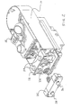
- FIG. 1 there is shown an isometric view of the respiratory system 10 that is part of an anesthesia machine and having a breathing circuit module 12 installed for use with a particular patient breathing circuit.
- the overall anesthesia machine showing the location of the particular portion is shown and described in copending US-A-5,692,494 of Pernetti et al.
- a bellows container 14 Shown connected to the respiratory system 10 is a bellows container 14 that contains a bellows that cooperates with a mechanical ventilator to provide powered breaths to the patient.
- a flexible breathing bag 16 is included and which can be manually squeezed or contracted by the clinician to provide that breath to the patient.
- a switch 18 is provided on the respiratory system 10 and is conveniently located so that the clinician can select between using a mechanical ventilator to breathe the patient or manually manipulate the flexible breathing bag 16.
- a carbon dioxide absorber assembly 20 which includes carbon dioxide absorbent canisters 22 to rid the recirculating gases from the patient of carbon dioxide so that some of the same expired gases can be reintroduced to the patient when the circle breathing circuit module is in use.
- the respiratory system 10 contains various other components of the overall system including check valves 24 that allow flow in the proper direction to and from the patient.
- a flow sensor module 26 interfits to the breathing circuit module 12 and includes ports 28,30 for providing a breathing gas to and from, respectively, the particular patient breathing circuit that is being used at the time.
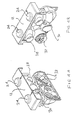
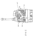
- FIG. 2 there is shown an isometric view of a breathing circuit module 12 in an exploded view showing how it is affixed to the respiratory system 10 and, in the preferred embodiment, the breathing circuit module 12 is affixed by means such as a thumb screw 32 that interfits with internal threads, (not shown) in the respiratory system 10 so that the appropriate pneumatic connection can be made between the breathing circuit module 12 and the respective manifold passages 36 (FIG. 6) of the respiratory system 10. Accordingly, another pneumatic connection is made between the breathing circuit module 12 and the fresh gas connection 34 from the anesthesia machine. (See FIG. 6)
- FIGS. 3A-B, 4A-B and 5A-B there are isometric views of the various breathing circuit modules 12 for the user that are a circle breathing circuit, an open or non/rebreathing patient circuit and a Bain or Mapleson D breathing circuit, respectively.
- the ports 28 and 30 are internally connected to provide the flows and receive the flows from each of those circuits.
- FIGS. 3A-B, 4A-B and 5A-B there are isometric views of the various breathing circuit modules 12 for the user that are a circle breathing circuit, an open or non/rebreathing patient circuit and a Bain or Mapleson D breathing circuit, respectively.
- the ports 28 and 30 are internally connected to provide the flows and receive the flows from each of those circuits.
- FIGS. 3A-B, 4A-B and 5A-B there are isometric views of the various breathing circuit modules 12 for the user that are a circle breathing circuit, an open or non/rebreathing patient circuit and a Bain or Mapleson D breathing circuit, respectively.
- a plurality of tabs 38 extend outwardly from each of the breathing circuit modules shown in FIGS. 3-6, each of which is in a unique configuration so as to allow the identification of that particular breathing circuit module 12. As shown in the preferred embodiment, two tabs 38 extend from each of the breathing circuit modules 12 and their specific use will be later explained.
- manifold passages 36 that provide the pneumatic breathing connections between the breathing circuit modules 12 and the respiratory system 10.
- the fresh gas connection 34 from the anesthesia machine.
- a sensor array 40 is located on the respiratory system and which receives the tabs 38 of the particular breathing circuit module and can identify that patient circuit module depending upon the position of those tabs 38.
- FIG. 7 there is shown an enlarged isometric view of a typical sensor array 40 that is used with the preferred embodiment and which has a plurality of sensors 42.
- Each of the sensors 42 may comprise a light source and a light detector such that the light emanating from the light source will normally fall upon the light detector, however, when one of the tabs 38 is inserted between the light source and the light detector, that light is interrupted and an identification of the particular breathing circuit module can be made.
- That information is supplied to a central processing unit (CPU) in the anesthesia machine so that the CPU can take the appropriate action, such as adapt the anesthesia machine flows and flow sensor algorithms to be appropriate for the particular patient breathing circuit being used at the time.
- CPU central processing unit
Landscapes
- Health & Medical Sciences (AREA)
- Emergency Medicine (AREA)
- Pulmonology (AREA)
- Engineering & Computer Science (AREA)
- Anesthesiology (AREA)
- Biomedical Technology (AREA)
- Heart & Thoracic Surgery (AREA)
- Hematology (AREA)
- Life Sciences & Earth Sciences (AREA)
- Animal Behavior & Ethology (AREA)
- General Health & Medical Sciences (AREA)
- Public Health (AREA)
- Veterinary Medicine (AREA)
- Measurement Of The Respiration, Hearing Ability, Form, And Blood Characteristics Of Living Organisms (AREA)
- Respiratory Apparatuses And Protective Means (AREA)
Claims (10)
- Ein Anästhesiegerät, das mit einem ausgewählten einer Mehrzahl von Patienten-Atmungskreisläufen verbindbar ist, wobei die Patienten-Atmungskreisläufe eine oder mehrere Schläuche aufweisen, die unterschiedliche charakteristische Frischgasströme liefern, die ein Anästhesiemittel enthalten, und zum Liefern und Empfangen von Atmungsgas an einen und von einem Patienten, wobei das Anästhesiegerät folgende Merkmale aufweist:eine Anästhesieverabreichungseinheit (10), die Öffnungen (34, 36) aufweist, die Atmungsgase für den Patienten liefern und empfangen und das Frischgas liefern, das ein Anästhesiemittel enthält;ein Strömungssensormodul (26), wobei das Strömungssensormodul (26) Öffnungen (28, 30) aufweist, die sich für eine Verbindung mit dem Schlauch oder den Schläuchen eines ausgewählten der Mehrzahl von Patienten-Atmungskreisläufen eignen; und gekennzeichnet durcheine Mehrzahl von austauschbaren Patienten-Kreislaufmodulen (12), von denen jedes für einen der Mehrzahl von Patienten-Atmungskreisläufen spezifisch ist, wobei das spezifische Patienten-Kreislaufmodul (12) zwischen der Anästhesieverabreichungseinheit (10) und dem Strömungssensormodul (26) angebracht ist, wobei sich das spezifische Patienten-Kreislaufmodul (12) zwischen der Anästhesieverabreichungseinheit (10) und den Strömungssensormodul (26) erstreckt, um die Atmungsgas- und Frischgasströme für den spezifischen der Mehrzahl von Patienten-Atmungskreisläufen herzustellen;einen Detektor zum Identifizieren, welches der Mehrzahl von Patienten-Kreislaufmodulen (12) zwischen der Anästhesieverabreichungseinheit (10) und dem Strömungssensormodul (26) angebracht ist, wobei der Detektor eine an dem Patienten-Kreislaufmodul (12) angebrachte erste Einrichtung (38) und eine an der Anästhesieverabreichungseinheit (10) angebrachte zweite Einrichtung (40) umfasst.
- Ein Anästhesiegerät gemäß Anspruch 1, bei dem der Detektor eine optische Erfassungseinrichtung umfasst.
- Ein Anästhesiegerät gemäß Anspruch 2, bei dem die optische Erfassungseinrichtung ein Array von einzelnen optischen Detektoren (42) umfasst, wobei die Einrichtung (38) an dem Patienten-Kreislaufmodul (12) bestimmte der optischen Detektoren des Arrays betreibt, um zu identifizieren, welches der Mehrzahl von Patienten-Kreislaufmodulen (12) zwischen der Anästhesieverabreichungseinheit (10) und dem Strömungssensormodul (26) angebracht ist.
- Ein Anästhesiegerät gemäß Anspruch 3, bei dem die einzelnen optischen Detektoren (42) eine Lichtquelle und einen Lichtdetektor umfassen, wobei das Patienten-Kreislaufmodul eine Einrichtung (38) aufweist, die das Licht in bestimmten der einzelnen optischen Detektoren (42) unterbricht, wenn das Patienten-Kreislaufmodul (12) zwischen der Anästhesieverabreichungseinheit (10) und dem Strömungssensormodul (26) angebracht ist.
- Ein Anästhesiegerät gemäß Anspruch 4, bei dem jedes der Patienten-Kreislaufmodule (26) eine einzigartige Konfiguration eines oder mehrerer Vorsprünge (38) umfasst, die sich von demselben nach außen erstrecken, um das Licht in den optischen Detektoren (42) zu unterbrechen, wenn das ausgewählte Patienten-Kreislaufmodul (12) zwischen der Anästhesieverabreichungseinheit (10) und dem Strömungssensormodul (26) angebracht ist.
- Ein Anästhesiegerät gemäß einem der vorhergehenden Ansprüche, bei dem die Anästhesieverabreichungseinheit (10) eine Zentralverarbeitungseinheit umfasst, wobei der Detektor mit der Zentralverarbeitungseinheit gekoppelt ist, um die Identifizierung dessen zu liefern, welches der Mehrzahl von Patienten-Kreislaufmodulen (12) zwischen der Anästhesieverabreichungseinheit (10) und dem Strömungssensormodul (26) angebracht ist.
- Ein Anästhesiegerät gemäß Anspruch 6, bei dem die Zentralverarbeitungseinheit Anästhesieverabreichungseinheit(10)-Betriebsalgorithmen für die Mehrzahl von Patienten-Atmungskreisläufen und eine Einrichtung zum Auswählen eines Betriebsalgorithmus gemäß der durch den Detektor gelieferten Angabe enthält.
- Ein Anästhesiegerät gemäß einem der vorhergehenden Ansprüche, bei dem das ausgewählte Patienten-Kreislaufmodul (12) ferner als für einen Nicht-Rückatmungs- oder offenen Patienten-Atmungskreislauf geeignet definiert ist.
- Ein Anästhesiegerät gemäß einem der Ansprüche 1 bis 7, bei dem das ausgewählte Patienten-Kreislaufmodul (12) ferner als für einen Rückzirkulierungs-Patienten-Atmungskreislauf geeignet definiert ist.
- Ein Anästhesiegerät gemäß einem der Ansprüche 1 bis 7, bei dem das ausgewählte Patienten-Kreislaufmodul (12) ferner als für einen Bain- oder Mapleson-D-Patienten-Atmungskreislauf geeignet definiert ist.
Applications Claiming Priority (4)
| Application Number | Priority Date | Filing Date | Title |
|---|---|---|---|
| US6205597P | 1997-10-15 | 1997-10-15 | |
| US62055 | 1997-10-15 | ||
| US09/042,241 US6571792B1 (en) | 1997-10-15 | 1998-03-13 | Smart modular anesthesia respiratory system |
| US42241 | 1998-03-13 |
Publications (3)
| Publication Number | Publication Date |
|---|---|
| EP0919253A2 EP0919253A2 (de) | 1999-06-02 |
| EP0919253A3 EP0919253A3 (de) | 1999-12-22 |
| EP0919253B1 true EP0919253B1 (de) | 2006-09-27 |
Family
ID=26719026
Family Applications (1)
| Application Number | Title | Priority Date | Filing Date |
|---|---|---|---|
| EP98308449A Expired - Lifetime EP0919253B1 (de) | 1997-10-15 | 1998-10-15 | Modulares Narkosebeatmungssystem |
Country Status (3)
| Country | Link |
|---|---|
| US (1) | US6571792B1 (de) |
| EP (1) | EP0919253B1 (de) |
| DE (1) | DE69835994T2 (de) |
Cited By (1)
| Publication number | Priority date | Publication date | Assignee | Title |
|---|---|---|---|---|
| WO2009062547A1 (en) | 2007-11-14 | 2009-05-22 | Maquet Critical Care Ab | Patient cassette with variable patient circuit volume |
Families Citing this family (44)
| Publication number | Priority date | Publication date | Assignee | Title |
|---|---|---|---|---|
| ATE414552T1 (de) * | 1999-04-07 | 2008-12-15 | Event Medical Ltd | Beatmungsgerät |
| AUPQ466999A0 (en) * | 1999-12-15 | 2000-01-13 | Dunlop, Colin | Anaesthetic apparatus |
| DE10158702A1 (de) * | 2001-11-29 | 2003-06-12 | Muefa Ag | Anschlusskassette |
| SE526014C2 (sv) * | 2002-09-11 | 2005-06-14 | Anmedic Ab | En apparat för att försörja en patient med en blandning av bärgas och ett gasformigt anestesimedel |
| US7188621B2 (en) | 2003-08-04 | 2007-03-13 | Pulmonetic Systems, Inc. | Portable ventilator system |
| US7607437B2 (en) * | 2003-08-04 | 2009-10-27 | Cardinal Health 203, Inc. | Compressor control system and method for a portable ventilator |
| US7527053B2 (en) * | 2003-08-04 | 2009-05-05 | Cardinal Health 203, Inc. | Method and apparatus for attenuating compressor noise |
| US8118024B2 (en) | 2003-08-04 | 2012-02-21 | Carefusion 203, Inc. | Mechanical ventilation system utilizing bias valve |
| US8156937B2 (en) | 2003-08-04 | 2012-04-17 | Carefusion 203, Inc. | Portable ventilator system |
| DE112005000942A5 (de) * | 2004-02-20 | 2007-05-24 | Weinmann Geräte für Medizin GmbH & Co. KG | Modulare Vorrichtung zur Befeuchtung von Atemgas |
| JP2008517682A (ja) * | 2004-10-26 | 2008-05-29 | エムアーペー・メディツィーン−テヒノロギー・ゲゼルシャフト・ミット・ベシュレンクテル・ハフツング | 呼吸ガスを投与するための装置及びその構成要素 |
| US7836882B1 (en) | 2005-01-07 | 2010-11-23 | Vetland Medical Sales And Services Llc | Electronic anesthesia delivery apparatus |
| DE202006021019U1 (de) | 2005-03-01 | 2011-11-08 | Resmed Ltd. | Erkennungssystem für eine Vorrichtung, die einem Patienten ein atembares Gas zuführt |
| US8496001B2 (en) * | 2005-06-08 | 2013-07-30 | Dräger Medical GmbH | Process and device for the automatic identification of breathing tubes |
| US7987848B2 (en) * | 2005-11-09 | 2011-08-02 | General Electric Company | System and method of integrating anesthesia agent monitoring in a respiratory carestation |
| US20080221930A1 (en) | 2007-03-09 | 2008-09-11 | Spacelabs Medical, Inc. | Health data collection tool |
| US7997885B2 (en) * | 2007-12-03 | 2011-08-16 | Carefusion 303, Inc. | Roots-type blower reduced acoustic signature method and apparatus |
| US8888711B2 (en) | 2008-04-08 | 2014-11-18 | Carefusion 203, Inc. | Flow sensor |
| US9549687B2 (en) * | 2008-08-08 | 2017-01-24 | General Electric Company | Patient transport apparatus with integrated subsystems for use in magnetic resonance imaging |
| BRPI0914035A2 (pt) * | 2008-10-17 | 2015-11-03 | Koninkl Philips Electronics Nv | ventilador e método para ventilar um paciente usando um ventilador |
| WO2011046636A1 (en) | 2009-10-16 | 2011-04-21 | Spacelabs Healthcare, Llc | Light enhanced flow tube |
| US9604020B2 (en) | 2009-10-16 | 2017-03-28 | Spacelabs Healthcare Llc | Integrated, extendable anesthesia system |
| WO2011119512A1 (en) | 2010-03-21 | 2011-09-29 | Spacelabs Healthcare, Llc | Multi-display bedside monitoring system |
| BR112013012329B1 (pt) | 2010-11-19 | 2021-05-04 | Spacelabs Healthcare, Llc | Dispositivo de tela para uso em um sistema de monitoramento de paciente e sistema de monitoramento de paciente |
| EP2651483B1 (de) * | 2010-12-17 | 2017-04-05 | Spacelabs Healthcare LLC | Integriertes erweiterbares anästhesiesystem |
| US9629566B2 (en) | 2011-03-11 | 2017-04-25 | Spacelabs Healthcare Llc | Methods and systems to determine multi-parameter managed alarm hierarchy during patient monitoring |
| CN104093990A (zh) | 2012-02-02 | 2014-10-08 | 爱赛特股份公司 | 用于呼吸器的隔音壳体 |
| DE102012009639B4 (de) * | 2012-05-15 | 2024-04-18 | Drägerwerk AG & Co. KGaA | Deckenversorgungseinheit |
| US10987026B2 (en) | 2013-05-30 | 2021-04-27 | Spacelabs Healthcare Llc | Capnography module with automatic switching between mainstream and sidestream monitoring |
| DE102013011983B4 (de) | 2013-07-18 | 2023-12-07 | Drägerwerk AG & Co. KGaA | Medizinische Messvorrichtung, Beatmungsvorrichtung und Verfahren zum Betrieb einer medizinischen Messvorrichtung oder zum Betrieb einer Beatmungsvorrichtung |
| CN104874076A (zh) * | 2014-02-28 | 2015-09-02 | 北京谊安医疗系统股份有限公司 | 麻醉机 |
| US10471229B2 (en) * | 2014-08-27 | 2019-11-12 | General Electric Company | Respiratory support system and patient transfer device therefor |
| AU2016243801B2 (en) | 2015-04-02 | 2020-05-21 | Hill-Rom Services Pte. Ltd. | Manifold for respiratory device |
| CN204798550U (zh) * | 2015-04-08 | 2015-11-25 | Ge医疗系统环球技术有限公司 | 麻醉机呼吸系统 |
| CA3011797C (en) * | 2016-01-21 | 2025-07-22 | Stryker Corporation | SAMPLE CASSETTE FOR COLLECTING FABRIC SAMPLES FROM A FLUID FLOW, CASSETTE COMPRISING MULTIPLE COLLECTION TRAYS TO HOLD MULTIPLE SAMPLES |
| DE102016007336B4 (de) | 2016-06-16 | 2023-08-10 | Drägerwerk AG & Co. KGaA | Medizintechnische Vorrichtung und Verfahren zur Alarmorganisation |
| DE102016013138B4 (de) | 2016-11-07 | 2018-09-27 | Drägerwerk AG & Co. KGaA | Medizintechnische Vorrichtung und Verfahren zur Bestimmung von Betriebssituationen bei einer medizintechnischen Vorrichtung |
| DE102018003027A1 (de) | 2018-04-13 | 2019-10-17 | Drägerwerk AG & Co. KGaA | Beatmungsvorrichtung |
| DE102018003026A1 (de) | 2018-04-13 | 2019-10-17 | Drägerwerk AG & Co. KGaA | Beatmungsvorrichtung mit einem Sicherheitsventil |
| CN114040710B (zh) | 2019-06-26 | 2024-09-03 | 太空实验室健康护理有限公司 | 使用身体穿戴传感器的数据修改所监测的生理数据 |
| CN111084925B (zh) * | 2019-12-30 | 2023-02-17 | 深圳迈瑞生物医疗电子股份有限公司 | 麻醉机 |
| CN116269912B (zh) * | 2020-12-30 | 2024-11-19 | 深圳迈瑞动物医疗科技股份有限公司 | 麻醉气体气路系统 |
| US12311104B2 (en) * | 2021-02-04 | 2025-05-27 | GE Precision Healthcare LLC | Ventilator systems and methods |
| CN119424853B (zh) * | 2023-07-31 | 2025-11-25 | 深圳迈瑞生物医疗电子股份有限公司 | 麻醉机 |
Family Cites Families (18)
| Publication number | Priority date | Publication date | Assignee | Title |
|---|---|---|---|---|
| GB623059A (en) * | 1946-11-06 | 1949-05-11 | Henry Rex Marrett | Improvements in or relating to apparatus for the administration of inhalent gas mixtures |
| US2872167A (en) * | 1956-09-24 | 1959-02-03 | Edmond O Pratt | Ether volatilizer |
| US3687137A (en) * | 1969-11-13 | 1972-08-29 | Donald W Johnson | Small animal anesthesia machine |
| US3815596A (en) * | 1973-01-26 | 1974-06-11 | Automation Ind Inc | Disposable face mask |
| DE3523948A1 (de) * | 1985-07-04 | 1987-01-08 | Draegerwerk Ag | Vorrichtung zur versorgung von narkosemittelabgabeeinrichtungen |
| DE3813520A1 (de) * | 1988-04-22 | 1989-11-02 | Draegerwerk Ag | Kodierung fuer eine narkoseeinrichtung |
| US5293865A (en) * | 1988-04-22 | 1994-03-15 | Dragerwerk Ag | Coding for an anesthetics device |
| US4991576A (en) * | 1988-10-11 | 1991-02-12 | Henkin Melvyn Lane | Anesthesia rebreathing system |
| CA2004930C (en) * | 1989-12-08 | 1996-04-02 | John Richard Sikora | Anaesthetic and respirator breathing circuit device |
| US5651357A (en) * | 1991-11-14 | 1997-07-29 | Ohmeda Inc. | Connection to a gas cylinder |
| DE4202025C2 (de) * | 1992-01-25 | 1995-02-02 | Draegerwerk Ag | Gebläseunterstütztes Atemschutzgerät mit einstellbarer Gebläseleistung |
| DE4310855C2 (de) * | 1993-04-02 | 1995-04-27 | Josef Dr Klimm | Einrichtung zur Überwachung wenigstens einer Verbindung zwischen zwei Elementen eines medizinischen Schlauchleitungssystems |
| FR2709669B1 (fr) * | 1993-09-09 | 1995-10-06 | Taema | Sous-ensemble de réseau de conduits de gaz et appareil d'anesthésie comportant un tel sous-ensemble. |
| IT1269700B (it) * | 1994-01-07 | 1997-04-15 | Abbott Lab | Sistema e apparecchiatura per collegare un contenitore di anestetico ad un vaporizzatore |
| FI97446C (fi) * | 1995-05-12 | 1996-12-27 | Instrumentarium Oy | Sovitelma ventilaattorin yhteydessä tapahtuvaa vuototestausta varten |
| US5682876A (en) * | 1996-03-20 | 1997-11-04 | Ohmeda Inc. | Absorber switch locking device |
| US5692494A (en) * | 1996-09-26 | 1997-12-02 | Ohmeda Inc. | Adjustable breathing circuit bag arm |
| US5778872A (en) * | 1996-11-18 | 1998-07-14 | Medlis, Inc. | Artificial ventilation system and methods of controlling carbon dioxide rebreathing |
-
1998
- 1998-03-13 US US09/042,241 patent/US6571792B1/en not_active Expired - Fee Related
- 1998-10-15 DE DE69835994T patent/DE69835994T2/de not_active Expired - Lifetime
- 1998-10-15 EP EP98308449A patent/EP0919253B1/de not_active Expired - Lifetime
Cited By (1)
| Publication number | Priority date | Publication date | Assignee | Title |
|---|---|---|---|---|
| WO2009062547A1 (en) | 2007-11-14 | 2009-05-22 | Maquet Critical Care Ab | Patient cassette with variable patient circuit volume |
Also Published As
| Publication number | Publication date |
|---|---|
| EP0919253A2 (de) | 1999-06-02 |
| DE69835994T2 (de) | 2007-08-02 |
| US6571792B1 (en) | 2003-06-03 |
| DE69835994D1 (de) | 2006-11-09 |
| EP0919253A3 (de) | 1999-12-22 |
Similar Documents
| Publication | Publication Date | Title |
|---|---|---|
| EP0919253B1 (de) | Modulares Narkosebeatmungssystem | |
| Mosley | Anesthesia equipment | |
| US4320754A (en) | Controllable partial rebreathing anesthesia circuit and respiratory assist device | |
| CN109069782B (zh) | 一种麻醉机及系统 | |
| US4502481A (en) | Device for manually ventilating a patient | |
| EP1795222B1 (de) | Narkosebeatmungssystem mit manueller Beatmung | |
| EP0903160B1 (de) | Beatmungstubus | |
| JP6130117B2 (ja) | 人工呼吸器装置および方法 | |
| US20110197887A1 (en) | Accessory connection and data synchronication in a ventilator | |
| EP0832662B1 (de) | Narkosesysteme | |
| JPH11137689A (ja) | ベンチレーター | |
| US8925549B2 (en) | Flow control adapter for performing spirometry and pulmonary function testing | |
| US20240261523A1 (en) | Integration and mode switching for respiratory apparatus | |
| EP0904793B1 (de) | Überwachung von Distalenvolumen | |
| JP5632925B2 (ja) | モジュール式換気システム | |
| RU2734464C1 (ru) | Клапан пациента для искусственной вентиляции легких пациента с помощью аппарата искусственной вентиляции легких | |
| EP3750584B1 (de) | Aktive und passive befeuchtungsvorrichtung zur montage in einem patientenbeatmungskreislauf | |
| US20250352755A1 (en) | Respiratory support device | |
| CN217366807U (zh) | 一种通气设备和流量传感器 | |
| EP4183435B1 (de) | Lüfter | |
| US20220370748A1 (en) | Passive oxygen mask vacuum regulation system | |
| CA1161332A (en) | Controllable partial rebreathing anesthesia circuit and respiratory assist device | |
| JP2000185061A (ja) | 動物用麻酔装置 | |
| JP2000051359A (ja) | 陽圧式人工呼吸補助装置 | |
| MILBURN et al. | The bird Mark 8 time cycled servo ventilator |
Legal Events
| Date | Code | Title | Description |
|---|---|---|---|
| PUAI | Public reference made under article 153(3) epc to a published international application that has entered the european phase |
Free format text: ORIGINAL CODE: 0009012 |
|
| AK | Designated contracting states |
Kind code of ref document: A2 Designated state(s): DE ES FR GB IT |
|
| AX | Request for extension of the european patent |
Free format text: AL;LT;LV;MK;RO;SI |
|
| PUAL | Search report despatched |
Free format text: ORIGINAL CODE: 0009013 |
|
| AK | Designated contracting states |
Kind code of ref document: A3 Designated state(s): AT BE CH CY DE DK ES FI FR GB GR IE IT LI LU MC NL PT SE |
|
| AX | Request for extension of the european patent |
Free format text: AL;LT;LV;MK;RO;SI |
|
| 17P | Request for examination filed |
Effective date: 20000614 |
|
| AKX | Designation fees paid |
Free format text: DE ES FR GB IT |
|
| 17Q | First examination report despatched |
Effective date: 20030618 |
|
| GRAP | Despatch of communication of intention to grant a patent |
Free format text: ORIGINAL CODE: EPIDOSNIGR1 |
|
| GRAS | Grant fee paid |
Free format text: ORIGINAL CODE: EPIDOSNIGR3 |
|
| GRAA | (expected) grant |
Free format text: ORIGINAL CODE: 0009210 |
|
| AK | Designated contracting states |
Kind code of ref document: B1 Designated state(s): DE ES FR GB IT |
|
| PG25 | Lapsed in a contracting state [announced via postgrant information from national office to epo] |
Ref country code: IT Free format text: LAPSE BECAUSE OF FAILURE TO SUBMIT A TRANSLATION OF THE DESCRIPTION OR TO PAY THE FEE WITHIN THE PRESCRIBED TIME-LIMIT;WARNING: LAPSES OF ITALIAN PATENTS WITH EFFECTIVE DATE BEFORE 2007 MAY HAVE OCCURRED AT ANY TIME BEFORE 2007. THE CORRECT EFFECTIVE DATE MAY BE DIFFERENT FROM THE ONE RECORDED. Effective date: 20060927 |
|
| REG | Reference to a national code |
Ref country code: GB Ref legal event code: FG4D |
|
| REF | Corresponds to: |
Ref document number: 69835994 Country of ref document: DE Date of ref document: 20061109 Kind code of ref document: P |
|
| PG25 | Lapsed in a contracting state [announced via postgrant information from national office to epo] |
Ref country code: ES Free format text: LAPSE BECAUSE OF FAILURE TO SUBMIT A TRANSLATION OF THE DESCRIPTION OR TO PAY THE FEE WITHIN THE PRESCRIBED TIME-LIMIT Effective date: 20070107 |
|
| ET | Fr: translation filed | ||
| PLBE | No opposition filed within time limit |
Free format text: ORIGINAL CODE: 0009261 |
|
| STAA | Information on the status of an ep patent application or granted ep patent |
Free format text: STATUS: NO OPPOSITION FILED WITHIN TIME LIMIT |
|
| 26N | No opposition filed |
Effective date: 20070628 |
|
| PGFP | Annual fee paid to national office [announced via postgrant information from national office to epo] |
Ref country code: GB Payment date: 20070918 Year of fee payment: 10 |
|
| PGFP | Annual fee paid to national office [announced via postgrant information from national office to epo] |
Ref country code: FR Payment date: 20081006 Year of fee payment: 11 |
|
| GBPC | Gb: european patent ceased through non-payment of renewal fee |
Effective date: 20081015 |
|
| PG25 | Lapsed in a contracting state [announced via postgrant information from national office to epo] |
Ref country code: GB Free format text: LAPSE BECAUSE OF NON-PAYMENT OF DUE FEES Effective date: 20081015 |
|
| REG | Reference to a national code |
Ref country code: FR Ref legal event code: ST Effective date: 20100630 |
|
| PG25 | Lapsed in a contracting state [announced via postgrant information from national office to epo] |
Ref country code: FR Free format text: LAPSE BECAUSE OF NON-PAYMENT OF DUE FEES Effective date: 20091102 |
|
| PGFP | Annual fee paid to national office [announced via postgrant information from national office to epo] |
Ref country code: DE Payment date: 20121029 Year of fee payment: 15 |
|
| REG | Reference to a national code |
Ref country code: DE Ref legal event code: R119 Ref document number: 69835994 Country of ref document: DE Effective date: 20140501 |
|
| PG25 | Lapsed in a contracting state [announced via postgrant information from national office to epo] |
Ref country code: DE Free format text: LAPSE BECAUSE OF NON-PAYMENT OF DUE FEES Effective date: 20140501 |