EP0919257A2 - Dispositif de serrage pour un système de rampe - Google Patents
Dispositif de serrage pour un système de rampe Download PDFInfo
- Publication number
- EP0919257A2 EP0919257A2 EP98118947A EP98118947A EP0919257A2 EP 0919257 A2 EP0919257 A2 EP 0919257A2 EP 98118947 A EP98118947 A EP 98118947A EP 98118947 A EP98118947 A EP 98118947A EP 0919257 A2 EP0919257 A2 EP 0919257A2
- Authority
- EP
- European Patent Office
- Prior art keywords
- boom system
- individual
- bearing
- measuring
- load
- Prior art date
- Legal status (The legal status is an assumption and is not a legal conclusion. Google has not performed a legal analysis and makes no representation as to the accuracy of the status listed.)
- Granted
Links
- 238000003860 storage Methods 0.000 claims description 24
- 238000005259 measurement Methods 0.000 claims description 11
- 230000005540 biological transmission Effects 0.000 claims description 5
- 238000012545 processing Methods 0.000 claims description 2
- 238000005452 bending Methods 0.000 description 9
- 239000004020 conductor Substances 0.000 description 6
- 238000006073 displacement reaction Methods 0.000 description 5
- 238000005520 cutting process Methods 0.000 description 3
- 230000003068 static effect Effects 0.000 description 3
- 238000010276 construction Methods 0.000 description 2
- 238000011156 evaluation Methods 0.000 description 2
- 239000000463 material Substances 0.000 description 2
- 125000006850 spacer group Chemical group 0.000 description 2
- 238000012549 training Methods 0.000 description 2
- 230000001133 acceleration Effects 0.000 description 1
- 238000004026 adhesive bonding Methods 0.000 description 1
- 230000015556 catabolic process Effects 0.000 description 1
- 238000006243 chemical reaction Methods 0.000 description 1
- 238000013461 design Methods 0.000 description 1
- 238000001514 detection method Methods 0.000 description 1
- 238000005553 drilling Methods 0.000 description 1
- 238000005516 engineering process Methods 0.000 description 1
- 238000007667 floating Methods 0.000 description 1
- 238000004519 manufacturing process Methods 0.000 description 1
- 238000000034 method Methods 0.000 description 1
- 238000013508 migration Methods 0.000 description 1
- 230000005012 migration Effects 0.000 description 1
- 238000001228 spectrum Methods 0.000 description 1
- 239000013598 vector Substances 0.000 description 1
Images


Classifications
-
- B—PERFORMING OPERATIONS; TRANSPORTING
- B66—HOISTING; LIFTING; HAULING
- B66C—CRANES; LOAD-ENGAGING ELEMENTS OR DEVICES FOR CRANES, CAPSTANS, WINCHES, OR TACKLES
- B66C23/00—Cranes comprising essentially a beam, boom, or triangular structure acting as a cantilever and mounted for translatory of swinging movements in vertical or horizontal planes or a combination of such movements, e.g. jib-cranes, derricks, tower cranes
- B66C23/88—Safety gear
- B66C23/90—Devices for indicating or limiting lifting moment
-
- A—HUMAN NECESSITIES
- A62—LIFE-SAVING; FIRE-FIGHTING
- A62C—FIRE-FIGHTING
- A62C27/00—Fire-fighting land vehicles
-
- B—PERFORMING OPERATIONS; TRANSPORTING
- B66—HOISTING; LIFTING; HAULING
- B66F—HOISTING, LIFTING, HAULING OR PUSHING, NOT OTHERWISE PROVIDED FOR, e.g. DEVICES WHICH APPLY A LIFTING OR PUSHING FORCE DIRECTLY TO THE SURFACE OF A LOAD
- B66F17/00—Safety devices, e.g. for limiting or indicating lifting force
- B66F17/006—Safety devices, e.g. for limiting or indicating lifting force for working platforms
-
- E—FIXED CONSTRUCTIONS
- E06—DOORS, WINDOWS, SHUTTERS, OR ROLLER BLINDS IN GENERAL; LADDERS
- E06C—LADDERS
- E06C5/00—Ladders characterised by being mounted on undercarriages or vehicles Securing ladders on vehicles
- E06C5/02—Ladders characterised by being mounted on undercarriages or vehicles Securing ladders on vehicles with rigid longitudinal members
- E06C5/04—Ladders characterised by being mounted on undercarriages or vehicles Securing ladders on vehicles with rigid longitudinal members capable of being elevated or extended ; Fastening means during transport, e.g. mechanical, hydraulic
Definitions
- the invention relates to a device for clamping a boom system of a swiveling, tilting and telescopic Tool over a support element on one Bogie of a vehicle, such as an emergency vehicle the fire department or the like, with a measuring device in the clamping area for the current determination of the load of the boom system.
- the boom system is clamped, in particular a ladder set in general on a so-called Bogie.
- the erection should and tilting the boom system.
- the attachment to the turret is not direct about a basic element of the ladder set, but there are for this purpose, floating support elements are provided on the turret, which form the bogie with the turret. Because of the U-shaped cross-sectional profile of the conductor elements of the Ladder set is a connection of the same to the support element only in the outer area of the outer conductor element, So the base element is possible to get inside not to obstruct the ladder set and so on further conductor elements within the U-shaped base element to be able to store.
- the carrier element in the longitudinal direction of the boom system designed such that it is the same as a bending beam Strength comes close to the swivel bending area to be able to optimize, especially what the lowering of the Boom system below the horizontal concerns.
- the Width of the support element is due to the width of the outrigger boom system, i.e. its ladder parts, by the total width of the construction so given to minimize on the bogie.
- a measuring system is known in which the bending stress of the boom system in / on the Clamping point is measured.
- the current distance measurement is carried out by the boom with knowledge of the error rate.
- Boom systems in the form of turntable ladders now work by increasing the basket capacity (from 2 to 3 man baskets), the provision of launcher inserts etc. the loads no longer in the primarily vertical of the U-shaped profile of the ladder elements, but outside and, among other things, cause non-negligible Torsional moments.
- the Raising angle of the aerial ladder system essentially the connecting elements of each Claim conductor elements with each other, d. H. the Ropes and / or the hydraulic cylinders up to storage in the clamping point.
- the object of the invention Basically, a device of the type mentioned to further develop that at the clamping point reliable interception of the constraining forces and moments and a reliable detection of the same is possible.
- the object is achieved by a Device of the type mentioned above solved that the clamping of the boom system by a static certain storage with measuring devices for measurement of the individual bearing forces is formed. So it is as Fixing a boom system a statically determined Storage with the possibility of measuring the individual Bearing forces are provided in this clamping.
- the design according to the invention also provides for this ensured that the measuring devices with the clamping be moved and so all three attacking directly Can capture forces and moments in the clamping. In this way, those acting on the boom system external and internal forces and moments individually classified and evaluated. Because with a boom system of the mentioned embodiment, the carrier element of the Mount is erected and the base element and the support element connecting storage "rigid" between this is arranged, but moves with the clamping are no additional corrective measures due to changed kinematic conditions of the Erection system, for example the erection cylinder etc. required.
- Base element of the boom system can be detached via the bearing is fixed on the support element.
- the number of individual bearings is chosen so that a statically determined storage of the entire system, however, the number of individual warehouses is minimal.
- This Requirement is met in that the storage by at least three individual bearings are formed.
- the individual warehouses with regard to their storage centers symmetrical to the plane of symmetry in the longitudinal direction of the base element of the boom system.
- the dimensions of this bearing arrangement are a matter of course from the dimensions of the end of the boom, that is Base element and / or the width or length of the carrier element certainly. This makes it possible to simple Way to ensure a clear storage and the to meet measurement requirements for this storage.
- the individual bearings are particularly advantageous for projection on the support element in the apices of an isosceles Triangular. To the lowest possible height to realize, it is preferably provided that the individual bearings in a common plane between the base element of the boom system and the support element are. But it can also be at least one of the individual bearings shifted vertically compared to the others be.
- the Measuring elements each one with its ends in a bore of a support component fixed on the support element mounted load measuring pin, its middle Area over an eye bed with one on the base element specified component for radial power transmission in Connection is established.
- Such individual bearings and measuring elements can be easily between at the interface level realize the base element and the support element.
- the Load measuring pin not only serves as part of the Measuring element, but at the same time as a component the individual storage. This embodiment has seen kinematically two relative degrees of freedom, namely one axial displacement and a rotation around the cylinder or Pin axis.
- the load measuring pin is designed as a hollow cylinder the inside of which measured the deformation (by bending) can be.
- Controlled deformation of the axis strain gauges are strain gauges provided on the inside of the bolts.
- Such Strain gauges (DMS) record depending on the version the bending stress also in two vertical directions the bolt axis, which then creates two forces as a measurement result.
- the respective components of the Forces determined by measurement technology are due to the arrangement of the load measuring pin.
- a device for processing the Measured values provided, as from the strain gauges measured moments and forces according to the equilibrium conditions to be taken into account and to be compared with permissible values Values must be determined. To when the limit is reached all initiated movements of the boom system being able to slow down or stop is preferred one that can be activated when the permissible measured value is exceeded Alarm unit provided, which is in training can be an acoustic alarm unit. Furthermore, at least one display device is for output of the measured values determined and thus for information of the provided by the respective operator.
- the Single bearing a spherical bearing that is, a spherical bearing in the eye bed, on to relative movements, deformations and to record flight deviations so that the kinematic Tolerance remains intact.
- every single bearing is kinematically compatible against angular errors and / or misalignments, because a single spatial shift at a storage location relative to the other corresponding rotations around the Triangle sides as well as displacements according to the Degrees of freedom in the individual bearings.
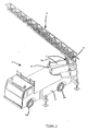
- the emergency vehicle 1 shown in FIG. 1 has known manner, a vehicle chassis 2 with front wheels 3a and rear wheels 3b and one of the vehicle chassis 2 supported vehicle body 4 in the form of a bogie from a turret 4a and a support member 5, the for swiveling with inclination to the horizontal or is articulated relative to the underground.
- the Carrier element 5 carries a boom system 6 of several displaceable against each other and thereby a variable in length Ladder sections forming supporting beams.
- an erection cylinder 7, which has its other end at the base of the turret 4 is set.
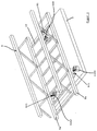
- FIGS. 2 and 3 serves the carrier element 5 as a receptacle for the lower or outer conductor part 8, called base element for short, the Boom system 6.
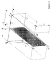
- This is the respective basic element 8 on the support element 5 via a statically determined storage clamped, which in the illustrated embodiment 2 and 3 each by three individual bearings B1, Ar1, Al1 or B2, Ar2 and Al2 is formed. 6 these bearings are shown schematically and by Al, Ar as well as B * and B. 2 and 3 also to the three individual bearings B1, Ar1, Al1 are located or B2, Ar2 and Al2 in one plane between the base element 8 and the carrier element 5. The same applies to the individual bearings Al, Ar and B in Fig. 6, while the bearing B * vertical by the height c compared to the bearings Al and Ar is moved out of the plane.
- the amount of triangle formed by the sides b and a becomes a1 designated.
- a Cartesian coordinate system is in Fig. 6 drawn, the axes or coordinates with x, y and z are designated. Such a Cartesian Coordinate system is used in analytical processes Breakdown of force and moment vectors is common.
- the y-axis represents in the illustrated embodiment Bisector of side b, on which then that too Camp B is located.
- FIGS. 2 and 3 shows themselves that this y-axis of the plane of symmetry of the carrier element and the base element of the boom system in the longitudinal direction of the boom.
- the origin the Cartesian coordinate system is in the middle on the connecting line b between the two on the X-axis arranged single bearings Al and Ar.
- the bearing arrangement is of the three individual bearings selected so that they are in one Connection level between the bottom of the base element 8 and the top of the carrier element 5 are.
- the dimensions of the bearing arrangement are due to the Dimensions of the characterized by the base element 8 Boom end and the width or length of the support element certainly.
- Base element 8 each on the underside of its longitudinal strips a and b via the individual bearings Ar2 and Al2 or Ar1, Al1 clamped on the support element 5, while the bearing B2 or B1 set on the underside of a rung 10 is.
- the individual warehouse B1 or B2 is located at the end of each boom 6.
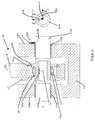
- the bearing B1 has one in the form of a hollow cylinder trained load pin 11B, with its Bolt ends 12a, 12b each in a bearing bore 13a, 13b of a carrier component 14 is mounted.
- a backup 15 protects the load pin 11B from rotation and axial Emigration due to friction.
- spacer elements 16 there is an axial adjustment in the z direction drawn load and measurement level LM and the load elements (Calibration).
- a cantilever part 18 firmly connected to the latter guided radially by the load measuring pin 11B. That way made a detachable connection. A shift is only in the axial direction, i.e. along the bolt axis S possible. Furthermore, the power transmission from the component 18 on the component 14 only radially.
- spherical in the outer bore 19 Bearing 20 (spherical bearing) with an inner spherical Tread 20a and an outer bearing bush surrounding it 20b used; the latter is in the axial direction of the Load measuring bolt through the eye bearing 17 on the one hand and on the other hand, a fuse 20c, such as a Snap rings, secured. 5 can be seen this spherical bearing 20 via a sliding material 21 on the Outside of the load pin 11B so as to certain limits misalignments by an angle of rotation ⁇ to be able to compensate kinematically.
- strain gauges 22a, 22b are on the inside of the load pin 11B parallel to the pin axis S in the area of the Longitudinal center L .
- a strain gauge 22a in the z direction and a strain gauge 22b in the x direction arranged.
- Such strain gauges 22a, 22b mostly consist of a carrier made of paper or plastic, on which a resistance wire applied or the type of printed circuit is made. The resistance of such a strain gauge changes with its length and becomes out for this reason for static and dynamic measurements used.
- strain gauges 22a, 22b are stretched and compressed at elastically deformable Bodies, here the load measuring bolts 11B, forces, Pressures, tensions, moments and accelerations or the like measured.
- the strain gauges are for this purpose 22a, 22b on the deforming load measuring pin 11B for example, applied by gluing.
- FIGS. 2 and 3 we refer below to FIGS. 2 and 3, in those embodiments for two different Bearing arrangements are shown.
- Fig. 2 is the bearing arrangement with respect to the individual pin axes symmetrical to the plane of symmetry in the longitudinal direction of the Boom 6 or base element 8 (y, z plane in Fig. 6).
- the axes of the load measuring bolts 11Ar and 11Al are in place perpendicular to this plane and cursed. they form together an axis of rotation that is perpendicular to the y, z plane stands.
- the pin axis of the load pin 11B is in this plane of symmetry and is perpendicular to the z, x plane (see also Fig. 6). Camp B1 is mainly on End of the base element 8 and thus the boom 6 is arranged.
- the Bearing arrangement not with respect to the individual pin axes symmetrical to the x, z plane, i.e. the plane of symmetry in Longitudinal direction of the boom 6 or base element 8.
- Die Axis 11Ar of the single bearing Ar2 is parallel to this Level, the axis of the load measuring pin 11Al of the single bearing Al2 perpendicular to this plane.
- the distances to the centers the force transmission in the two load measuring bolts 11Ar and 11A1 are again symmetrical to the y-, z plane and aligned. They are also perpendicular to the y-, z-plane arranged.
- the arrangement is interchangeable.
- the Pin axis of the load measuring pin 11B of the single bearing B2 lies in the plane of symmetry and is perpendicular to the z-, x plane. Again, it is primarily at the end of the boom 6 or base element 8 arranged.
- this bearing arrangement is more advantageous, as they are free of internal tension in the bearings with each other due to the deformation of the boom end and carrier element.
- This bearing arrangement is corresponding also technically free of errors on it are based.
- FIG. 6 A further embodiment variant can be seen in FIG. 6, where the single warehouse B * is not on one level Bearings Ar and Al lies, but in the vertical around the Distance c is shifted. This only changes the evaluation of the moment balance for the torsional moments Ar by the additional operation + (c * Bx).
Landscapes
- Engineering & Computer Science (AREA)
- Mechanical Engineering (AREA)
- Life Sciences & Earth Sciences (AREA)
- Geology (AREA)
- Structural Engineering (AREA)
- Health & Medical Sciences (AREA)
- Public Health (AREA)
- Business, Economics & Management (AREA)
- Emergency Management (AREA)
- Forklifts And Lifting Vehicles (AREA)
- Jib Cranes (AREA)
Applications Claiming Priority (2)
| Application Number | Priority Date | Filing Date | Title |
|---|---|---|---|
| DE19745923 | 1997-10-17 | ||
| DE19745923A DE19745923A1 (de) | 1997-10-17 | 1997-10-17 | Vorrichtung zum Einspannen eines Auslegersystems |
Publications (3)
| Publication Number | Publication Date |
|---|---|
| EP0919257A2 true EP0919257A2 (fr) | 1999-06-02 |
| EP0919257A3 EP0919257A3 (fr) | 2000-10-11 |
| EP0919257B1 EP0919257B1 (fr) | 2004-12-22 |
Family
ID=7845841
Family Applications (1)
| Application Number | Title | Priority Date | Filing Date |
|---|---|---|---|
| EP98118947A Expired - Lifetime EP0919257B1 (fr) | 1997-10-17 | 1998-10-07 | Dispositif de serrage pour un système de rampe |
Country Status (3)
| Country | Link |
|---|---|
| EP (1) | EP0919257B1 (fr) |
| AT (1) | ATE285273T1 (fr) |
| DE (2) | DE19745923A1 (fr) |
Families Citing this family (7)
| Publication number | Priority date | Publication date | Assignee | Title |
|---|---|---|---|---|
| DE29907718U1 (de) | 1999-04-30 | 2000-06-29 | BISON stematec Maschinenbau- und Hubarbeitsbühnen Produktionsgesellschaft mbH, 02708 Löbau | Vorrichtung zur Ablage eines Hubarms |
| DE10059877C1 (de) * | 2000-12-01 | 2002-05-16 | Guenzburger Steigtechnik Munk | Schwenkbarer Handlauf |
| DE10353134A1 (de) * | 2003-11-14 | 2005-06-09 | Marte Feuerwehrfahrzeuge Feuerwehrtechnologie Ges.M.B.H. | Rettungshubgerät |
| DE102005060185A1 (de) * | 2005-12-14 | 2007-06-28 | Repower Systems Ag | Fahrzeug, Trägereinheit und Verfahren zum Transport eines großvolumigen Bauteils mit Überlänge |
| DE102010050683A1 (de) * | 2010-11-06 | 2012-05-10 | Jungheinrich Aktiengesellschaft | Flurförderzeug mit Verformungssensor im Neigezylinder |
| US20240409383A1 (en) | 2023-06-08 | 2024-12-12 | Crown Equipment Corporation | Boom assembly having an adapter |
| EP4527781A1 (fr) * | 2023-08-25 | 2025-03-26 | Crown Equipment Corporation | Système de surveillance d'intégrité pour ensemble flèche |
Family Cites Families (5)
| Publication number | Priority date | Publication date | Assignee | Title |
|---|---|---|---|---|
| DE2205968A1 (de) * | 1972-02-09 | 1973-08-16 | Kloeckner Humboldt Deutz Ag | Fahrbare ausziehleiter, insbesondere kraftfahrdrehleiter |
| US4456093A (en) * | 1981-06-16 | 1984-06-26 | Interstate Electronics Corp. | Control system for aerial work platform machine and method of controlling an aerial work platform machine |
| DE3322270C3 (de) * | 1983-06-21 | 1989-02-02 | Liebherr-Werk Bischofshofen GmbH, Bischofshofen | Fahrwerk, vorzugsweise Raupenfahrwerk für Krane |
| DE3340438C2 (de) * | 1983-11-09 | 1986-08-07 | Dr. Brandt GmbH, 4630 Bochum | Meßanordnung für Kraftmessungen an einem Auflager eines Wägeobjektes |
| DE3500891C1 (de) * | 1985-01-12 | 1986-06-26 | Krupp Mak Maschinenbau Gmbh, 2300 Kiel | Meßelement zur Ermittlung von Belastungen mit Hilfe von Schubspannungen |
-
1997
- 1997-10-17 DE DE19745923A patent/DE19745923A1/de not_active Withdrawn
-
1998
- 1998-10-07 EP EP98118947A patent/EP0919257B1/fr not_active Expired - Lifetime
- 1998-10-07 DE DE59812407T patent/DE59812407D1/de not_active Expired - Fee Related
- 1998-10-07 AT AT98118947T patent/ATE285273T1/de not_active IP Right Cessation
Non-Patent Citations (1)
| Title |
|---|
| None |
Also Published As
| Publication number | Publication date |
|---|---|
| ATE285273T1 (de) | 2005-01-15 |
| DE19745923A1 (de) | 1999-04-22 |
| EP0919257A3 (fr) | 2000-10-11 |
| EP0919257B1 (fr) | 2004-12-22 |
| DE59812407D1 (de) | 2005-01-27 |
Similar Documents
| Publication | Publication Date | Title |
|---|---|---|
| DE60012781T2 (de) | Verfahren zur erfassung des dynamischen verhaltens eines fahrzeugs auf einem prüfstand | |
| DE3307574C2 (de) | Lastzelle | |
| EP2069741B1 (fr) | Dispositif et procédé de détermination des paramètres d'inertie d'un corps | |
| DE2011686A1 (de) | Kraftmeßgerat | |
| CH656714A5 (de) | Gewichtsmess- und ausgleichsvorrichtung. | |
| DE2232536C3 (de) | Überlastsicherung für Auslegerkrane, insbesondere Teleskopkrane | |
| DE2027119A1 (de) | Elektrische Waage | |
| DE3804242C2 (fr) | ||
| DE3331708A1 (de) | Vorrichtung zur kontrolle und/oder eichung einer drehmomentmessvorrichtung | |
| EP0919257B1 (fr) | Dispositif de serrage pour un système de rampe | |
| DE2802947A1 (de) | Dynamometrische messanordnung fuer das kippmoment eines hebezeugauslegers | |
| DE19612626A1 (de) | Gerät zum Positionieren und Transportieren von Flugzeugtriebwerken | |
| DE2948774A1 (de) | Kraftmesseinrichtung fuer maschine mit ausleger, insbesondere zur ueberwachung der abkippung hiervon | |
| DE2121357A1 (de) | Lastmeßsystem und Kraftubertragungs anordnung hierfür | |
| DE102018213739A1 (de) | System zur Positionierung und Nivellierung | |
| DE10359460B4 (de) | Wägezelle | |
| DE3226046C2 (fr) | ||
| DE19703735C2 (de) | Längenveränderliches Element | |
| DE20019106U1 (de) | Stativ mit Parallelogrammträger und Balanciermechanismus | |
| DE3507957C2 (fr) | ||
| DD218458A1 (de) | Kraft-momenten-fuehler | |
| DE3442005C2 (de) | Einrichtung zum Bestimmen von auf ein Meßobjekt wirkenden Momenten | |
| DE3340438A1 (de) | Messanordnung fuer kraftmessungen mittels dehnmessstreifen | |
| DE2300337A1 (de) | Vorrichtung zum wiegen von schienenfahrzeugen | |
| DE3528727A1 (de) | Einrichtung zur zerlegung von vektorkraeften |
Legal Events
| Date | Code | Title | Description |
|---|---|---|---|
| PUAI | Public reference made under article 153(3) epc to a published international application that has entered the european phase |
Free format text: ORIGINAL CODE: 0009012 |
|
| AK | Designated contracting states |
Kind code of ref document: A2 Designated state(s): AT CH DE ES FI FR GB IT LI NL SE |
|
| AX | Request for extension of the european patent |
Free format text: AL;LT;LV;MK;RO;SI |
|
| RAP1 | Party data changed (applicant data changed or rights of an application transferred) |
Owner name: METZ FEUERWEHRTECHNIK GMBH & CO. KG |
|
| RAP1 | Party data changed (applicant data changed or rights of an application transferred) |
Owner name: METZ AERIALS GMBH & CO KG. |
|
| RAP1 | Party data changed (applicant data changed or rights of an application transferred) |
Owner name: METZ AERIALS GMBH & CO KG |
|
| PUAL | Search report despatched |
Free format text: ORIGINAL CODE: 0009013 |
|
| AK | Designated contracting states |
Kind code of ref document: A3 Designated state(s): AT BE CH CY DE DK ES FI FR GB GR IE IT LI LU MC NL PT SE |
|
| AX | Request for extension of the european patent |
Free format text: AL;LT;LV;MK;RO;SI |
|
| RIC1 | Information provided on ipc code assigned before grant |
Free format text: 7A 62C 2/00 A, 7A 62C 27/00 B, 7B 66C 23/90 B, 7B 66F 17/00 B, 7E 06C 5/34 B, 7E 06C 5/04 B, 7E 06C 5/36 B |
|
| 17P | Request for examination filed |
Effective date: 20010103 |
|
| AKX | Designation fees paid |
Free format text: AT CH DE ES FI FR GB IT LI NL SE |
|
| GRAP | Despatch of communication of intention to grant a patent |
Free format text: ORIGINAL CODE: EPIDOSNIGR1 |
|
| GRAS | Grant fee paid |
Free format text: ORIGINAL CODE: EPIDOSNIGR3 |
|
| GRAA | (expected) grant |
Free format text: ORIGINAL CODE: 0009210 |
|
| AK | Designated contracting states |
Kind code of ref document: B1 Designated state(s): AT CH DE ES FI FR GB IT LI NL SE |
|
| PG25 | Lapsed in a contracting state [announced via postgrant information from national office to epo] |
Ref country code: NL Free format text: LAPSE BECAUSE OF FAILURE TO SUBMIT A TRANSLATION OF THE DESCRIPTION OR TO PAY THE FEE WITHIN THE PRESCRIBED TIME-LIMIT Effective date: 20041222 Ref country code: IT Free format text: LAPSE BECAUSE OF FAILURE TO SUBMIT A TRANSLATION OF THE DESCRIPTION OR TO PAY THE FEE WITHIN THE PRE;WARNING: LAPSES OF ITALIAN PATENTS WITH EFFECTIVE DATE BEFORE 2007 MAY HAVE OCCURRED AT ANY TIME BEFORE 2007. THE CORRECT EFFECTIVE DATE MAY BE DIFFERENT FROM THE ONE RECORDED.SCRIBED TIME-LIMIT Effective date: 20041222 Ref country code: GB Free format text: LAPSE BECAUSE OF FAILURE TO SUBMIT A TRANSLATION OF THE DESCRIPTION OR TO PAY THE FEE WITHIN THE PRESCRIBED TIME-LIMIT Effective date: 20041222 Ref country code: FR Free format text: LAPSE BECAUSE OF FAILURE TO SUBMIT A TRANSLATION OF THE DESCRIPTION OR TO PAY THE FEE WITHIN THE PRESCRIBED TIME-LIMIT Effective date: 20041222 Ref country code: FI Free format text: LAPSE BECAUSE OF FAILURE TO SUBMIT A TRANSLATION OF THE DESCRIPTION OR TO PAY THE FEE WITHIN THE PRESCRIBED TIME-LIMIT Effective date: 20041222 |
|
| REG | Reference to a national code |
Ref country code: GB Ref legal event code: FG4D Free format text: NOT ENGLISH |
|
| REG | Reference to a national code |
Ref country code: CH Ref legal event code: EP |
|
| REF | Corresponds to: |
Ref document number: 59812407 Country of ref document: DE Date of ref document: 20050127 Kind code of ref document: P |
|
| PG25 | Lapsed in a contracting state [announced via postgrant information from national office to epo] |
Ref country code: SE Free format text: LAPSE BECAUSE OF FAILURE TO SUBMIT A TRANSLATION OF THE DESCRIPTION OR TO PAY THE FEE WITHIN THE PRESCRIBED TIME-LIMIT Effective date: 20050322 |
|
| PG25 | Lapsed in a contracting state [announced via postgrant information from national office to epo] |
Ref country code: ES Free format text: LAPSE BECAUSE OF FAILURE TO SUBMIT A TRANSLATION OF THE DESCRIPTION OR TO PAY THE FEE WITHIN THE PRESCRIBED TIME-LIMIT Effective date: 20050402 |
|
| NLV1 | Nl: lapsed or annulled due to failure to fulfill the requirements of art. 29p and 29m of the patents act | ||
| GBV | Gb: ep patent (uk) treated as always having been void in accordance with gb section 77(7)/1977 [no translation filed] |
Effective date: 20041222 |
|
| PG25 | Lapsed in a contracting state [announced via postgrant information from national office to epo] |
Ref country code: AT Free format text: LAPSE BECAUSE OF NON-PAYMENT OF DUE FEES Effective date: 20051007 |
|
| PLBE | No opposition filed within time limit |
Free format text: ORIGINAL CODE: 0009261 |
|
| STAA | Information on the status of an ep patent application or granted ep patent |
Free format text: STATUS: NO OPPOSITION FILED WITHIN TIME LIMIT |
|
| PG25 | Lapsed in a contracting state [announced via postgrant information from national office to epo] |
Ref country code: LI Free format text: LAPSE BECAUSE OF NON-PAYMENT OF DUE FEES Effective date: 20051031 Ref country code: CH Free format text: LAPSE BECAUSE OF NON-PAYMENT OF DUE FEES Effective date: 20051031 |
|
| 26N | No opposition filed |
Effective date: 20050923 |
|
| EN | Fr: translation not filed | ||
| PG25 | Lapsed in a contracting state [announced via postgrant information from national office to epo] |
Ref country code: DE Free format text: LAPSE BECAUSE OF NON-PAYMENT OF DUE FEES Effective date: 20060503 |
|
| REG | Reference to a national code |
Ref country code: CH Ref legal event code: PL |