EP0919319A1 - Dispositif pour l'insertion et le positionnement d'au moins deux tÔles dans une machine de soudage au rayon laser - Google Patents
Dispositif pour l'insertion et le positionnement d'au moins deux tÔles dans une machine de soudage au rayon laser Download PDFInfo
- Publication number
- EP0919319A1 EP0919319A1 EP98121345A EP98121345A EP0919319A1 EP 0919319 A1 EP0919319 A1 EP 0919319A1 EP 98121345 A EP98121345 A EP 98121345A EP 98121345 A EP98121345 A EP 98121345A EP 0919319 A1 EP0919319 A1 EP 0919319A1
- Authority
- EP
- European Patent Office
- Prior art keywords
- welding
- positioning
- positioning rollers
- welding gap
- parallel
- Prior art date
- Legal status (The legal status is an assumption and is not a legal conclusion. Google has not performed a legal analysis and makes no representation as to the accuracy of the status listed.)
- Withdrawn
Links
- 238000003466 welding Methods 0.000 title claims abstract description 55
- 239000002184 metal Substances 0.000 title claims description 8
- 238000003780 insertion Methods 0.000 claims abstract description 23
- 230000037431 insertion Effects 0.000 claims abstract description 23
- 238000006073 displacement reaction Methods 0.000 claims description 3
- 239000000463 material Substances 0.000 claims description 2
- 230000000284 resting effect Effects 0.000 abstract 1
- 241000239290 Araneae Species 0.000 description 2
- 238000000034 method Methods 0.000 description 2
- 230000007257 malfunction Effects 0.000 description 1
Images


Classifications
-
- B—PERFORMING OPERATIONS; TRANSPORTING
- B23—MACHINE TOOLS; METAL-WORKING NOT OTHERWISE PROVIDED FOR
- B23K—SOLDERING OR UNSOLDERING; WELDING; CLADDING OR PLATING BY SOLDERING OR WELDING; CUTTING BY APPLYING HEAT LOCALLY, e.g. FLAME CUTTING; WORKING BY LASER BEAM
- B23K26/00—Working by laser beam, e.g. welding, cutting or boring
- B23K26/20—Bonding
- B23K26/21—Bonding by welding
- B23K26/24—Seam welding
- B23K26/26—Seam welding of rectilinear seams
-
- B—PERFORMING OPERATIONS; TRANSPORTING
- B23—MACHINE TOOLS; METAL-WORKING NOT OTHERWISE PROVIDED FOR
- B23K—SOLDERING OR UNSOLDERING; WELDING; CLADDING OR PLATING BY SOLDERING OR WELDING; CUTTING BY APPLYING HEAT LOCALLY, e.g. FLAME CUTTING; WORKING BY LASER BEAM
- B23K37/00—Auxiliary devices or processes, not specially adapted for a procedure covered by only one of the other main groups of this subclass
- B23K37/04—Auxiliary devices or processes, not specially adapted for a procedure covered by only one of the other main groups of this subclass for holding or positioning work
- B23K37/0408—Auxiliary devices or processes, not specially adapted for a procedure covered by only one of the other main groups of this subclass for holding or positioning work for planar work
-
- B—PERFORMING OPERATIONS; TRANSPORTING
- B23—MACHINE TOOLS; METAL-WORKING NOT OTHERWISE PROVIDED FOR
- B23K—SOLDERING OR UNSOLDERING; WELDING; CLADDING OR PLATING BY SOLDERING OR WELDING; CUTTING BY APPLYING HEAT LOCALLY, e.g. FLAME CUTTING; WORKING BY LASER BEAM
- B23K37/00—Auxiliary devices or processes, not specially adapted for a procedure covered by only one of the other main groups of this subclass
- B23K37/04—Auxiliary devices or processes, not specially adapted for a procedure covered by only one of the other main groups of this subclass for holding or positioning work
- B23K37/047—Auxiliary devices or processes, not specially adapted for a procedure covered by only one of the other main groups of this subclass for holding or positioning work moving work to adjust its position between soldering, welding or cutting steps
Definitions
- the invention relates to a device for inserting and Position at least two sheet metal boards of the same or different thicknesses, shapes, sizes or materials to each other in a laser beam welding machine with both sides of the welding gap arranged clamping devices, one Welding table, against the table surface of which the sheet metal plates and a welding optics that run parallel to the Welding gap is movable.
- the transport tongs are mounted on guides arranged at right angles to the welding gap and are moved back and forth as well as opened and closed by different drives (US Pat. No. 5,266,770). All of these solutions require that the boards are already positioned very precisely when they are placed on the welding table or when they are inserted into the transport tongs and that there are no deviations from the position of the welding gap. Since this is not the case, inaccurate and inclined boards are a frequent cause of malfunctions, which then have to be fixed in a time-consuming manner.
- the positional accuracy of the boards in the longitudinal direction of the Welding gap is due to the on and with a pair of rails movable positioning rollers achieved.
- the movability serves both to position the positioning rollers as well as the generation of a contact movement by the positioning rollers one rail opposite the positioning rollers the other rail. Thanks to the lifting drive, everyone is Positioning rollers can be lowered below the table level an easy and quick way to discharge the to create welded boards.
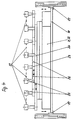
- a laser beam welding machine are perpendicular to Weld joint two guide rails 1, 2 attached to the base of the frame (Fig. 1).
- a slide 3 can be moved on both sides of the welding gap stored.
- On each carriage 3 there is a vertical one at the outer end Column 4 welded over the height of the welding table 5 protrudes.
- On the slide 3 and on their free Both columns 4 are connected at the ends by a cross member 6.
- On the middle of the lower cross member 6 is a piston rod 7 of a pneumatic cylinder 8 articulated.
- the pneumatic cylinder 8 is with an actuator 9 of a numerically controlled Adjusting drive 10 connected, the drive member 11 on Rack floor is attached.
- each pillar 4 there is something about Height of the welding table 5 an arm pointing to the welding joint 12 firmly attached, the length of which is approximately that of the slide 3 corresponds.
- an insertion beam 13 welded.
- the insertion bar 13 has a rectangular hollow profile and a length slightly smaller is the clear width between the front frame parts.
- U-shaped hooks 14 On the insertion bar 13 are on U-shaped hooks 14 a number of short-stroke cylinders 15 easily displaceable and lockable stored.
- the short-stroke cylinder on each piston rod 15 is an insertion roller which can be easily rotated about a vertical axis 16 stored. Your outer surface is with a V-shaped groove. This groove is at the level of the Welding table 5.
- trusses 18 On the two front frame parts are on both sides of the Welding gap support angle 17 for parallel to the welding gap arranged trusses 18 attached (Fig. 4). These trusses 18 are immediately adjacent to the longitudinal surfaces of the Welding table 5 stored (Fig. 3). On each of the trusses 18 with the interposition of a pressure hose 19 supported by this lifting and lowering plate 20.
- This Plate 20 carries two mutually parallel guideways 21; 22. On each of these guideways 21; 22 there is a longitudinal one movable rail 23, 24 mounted on the top again longitudinally displaceable positioning rollers 25 stored are. Both rails 23, 24 are arranged one above the other. The upper rail 23 is at the welding gap pointing edge cut out like a comb.
- the facility operates as follows: The blanks 27 to be welded are positioned on a feed carriage in accordance with the design. There they are removed by means of a suction spider, which is moved by a transport robot. Then the transport robot moves the suction spider to a predetermined position above the laser beam welding machine and lowers it to such an extent that the plates 27 come to rest on the insertion surfaces. At this point, the insertion bar 13 is in its rearmost position and the positioning rollers 25 of the uppermost rail 23 are approximately 10 mm outside the nominal size. The positioning rollers 25 on the lower rail 24 are kept at their desired dimensions.
- the pneumatic cylinder 8 now receives compressed air on the right-hand side and thereby moves the insertion beam 13 by the amount of its maximum stroke in the direction of the welding gap.
- the insertion rollers 16 of the short-stroke cylinders 15 come into contact with the rear edges of the plates 27 and push them in the direction of the welding gap.
- the short stroke cylinders 15 have been previously set so that their insertion rollers 16 come close to the side edges of each board 27 to attack.
- the numerically controlled adjustment drive 10 executes the additional path which results from the length of the blank and thereby brings the blank 27 up to approximately 15 mm from the welding gap.
- the front sections of the boards 27 are already between the positioning rollers 25.
- the upper rail 23 with its positioning rollers 25 has a displacement movement in the direction of the positioning rollers 25 of the lower rail 24.
- the boards 27 are on their Target position brought in the longitudinal direction of the welding gap.
- the short-stroke cylinders 15 receive pressure and thereby push the boards 27 onto the counter board.
- the arrangement of two short-stroke cylinders 15 compensates for inclined positions of the plates 27 and creates a uniform contact with the edge of the counter plate.
- the plates 27 are positioned quickly and precisely both transversely and along the welding gap and are clamped by means of a clamping device 28. It is within the scope of the invention to set the positioning rollers 25 of the upper rail 23 to their desired position and to carry out the displacement movement by means of the positioning rollers 25 of the lower rail 24. This process takes place in the same way if a board 27 is positioned against center stops.
- the positioning rollers 25 are lowered into their lower position and the insertion rollers 16 are returned to their rear starting position.
- the welded circuit board 27 is pulled out of the laser beam welding machine along the welding gap and, if necessary, fed to a further processing.
- new blanks 27 are already moved to an intermediate position in front of or next to the laser beam welding machine.
Landscapes
- Physics & Mathematics (AREA)
- Optics & Photonics (AREA)
- Engineering & Computer Science (AREA)
- Mechanical Engineering (AREA)
- Plasma & Fusion (AREA)
- Laser Beam Processing (AREA)
Applications Claiming Priority (2)
| Application Number | Priority Date | Filing Date | Title |
|---|---|---|---|
| DE19752095 | 1997-11-25 | ||
| DE19752095A DE19752095B4 (de) | 1997-11-25 | 1997-11-25 | Einrichtung zum Einschieben und Positionieren von mindestens zwei Blechplatinen in eine Laserstrahlschweißmaschine |
Publications (1)
| Publication Number | Publication Date |
|---|---|
| EP0919319A1 true EP0919319A1 (fr) | 1999-06-02 |
Family
ID=7849707
Family Applications (1)
| Application Number | Title | Priority Date | Filing Date |
|---|---|---|---|
| EP98121345A Withdrawn EP0919319A1 (fr) | 1997-11-25 | 1998-11-10 | Dispositif pour l'insertion et le positionnement d'au moins deux tÔles dans une machine de soudage au rayon laser |
Country Status (2)
| Country | Link |
|---|---|
| EP (1) | EP0919319A1 (fr) |
| DE (1) | DE19752095B4 (fr) |
Cited By (4)
| Publication number | Priority date | Publication date | Assignee | Title |
|---|---|---|---|---|
| CN109926741A (zh) * | 2018-09-28 | 2019-06-25 | 湖北华信机械发展有限公司 | 一种吹灰器梁体焊接系统 |
| CN110170793A (zh) * | 2019-07-08 | 2019-08-27 | 汉能机器人自动化(丹阳)有限公司 | 可移动变位机 |
| CN110449803A (zh) * | 2019-07-25 | 2019-11-15 | 安徽卓科智能装备有限公司 | 一种履带式收割机底盘自动化焊接夹具 |
| CN114799523A (zh) * | 2022-06-28 | 2022-07-29 | 南通威朗运动用品有限公司 | 一种健身器材生产用金属杆焊接装置 |
Families Citing this family (2)
| Publication number | Priority date | Publication date | Assignee | Title |
|---|---|---|---|---|
| CN116060961A (zh) * | 2023-02-07 | 2023-05-05 | 浙江恒昕源金属科技股份有限公司 | 用于金属板切割的定位装置 |
| CN117798526B (zh) * | 2023-12-29 | 2025-10-28 | 安徽东海裕祥智能装备科技有限公司 | 一种地轨自调节横梁安装结构 |
Citations (2)
| Publication number | Priority date | Publication date | Assignee | Title |
|---|---|---|---|---|
| US5266770A (en) * | 1990-10-20 | 1993-11-30 | Bwg Bergwerk-Und Walzwerk-Maschinebau Gmbh | Strip welding machine |
| EP0807487A2 (fr) * | 1996-05-13 | 1997-11-19 | Krupp Drauz Ingenieurbetrieb GmbH | Dispositif pour transporter, serrer et souder par faisceau laser au moins deux platines de tÔle |
Family Cites Families (5)
| Publication number | Priority date | Publication date | Assignee | Title |
|---|---|---|---|---|
| DE4127271C1 (fr) * | 1991-08-17 | 1993-04-15 | Thyssen Stahl Ag, 4100 Duisburg, De | |
| FR2698575B1 (fr) * | 1992-11-30 | 1995-03-17 | Lorraine Laminage | Dispositif de positionnement de flans de tôle dans une installation de soudage bord à bord en continu de ces flans de tôle. |
| DE4441539C1 (de) * | 1994-11-22 | 1996-06-27 | Arnold Karl H Masch | Vorrichtung zum lagegerechten Positionieren von Blechplatinen für das Strahlschweißen |
| AT403894B (de) * | 1995-05-04 | 1998-06-25 | Berndorf Band Gmbh | Vorrichtung zum elektromagnetischen aufspannen und zum verbinden, insbesondere verschweissen, der endbereiche von blechen |
| EP0774320A1 (fr) * | 1995-11-20 | 1997-05-21 | Elpatronic Ag | Méthode de positionnement et d'alignement de pièces |
-
1997
- 1997-11-25 DE DE19752095A patent/DE19752095B4/de not_active Expired - Fee Related
-
1998
- 1998-11-10 EP EP98121345A patent/EP0919319A1/fr not_active Withdrawn
Patent Citations (2)
| Publication number | Priority date | Publication date | Assignee | Title |
|---|---|---|---|---|
| US5266770A (en) * | 1990-10-20 | 1993-11-30 | Bwg Bergwerk-Und Walzwerk-Maschinebau Gmbh | Strip welding machine |
| EP0807487A2 (fr) * | 1996-05-13 | 1997-11-19 | Krupp Drauz Ingenieurbetrieb GmbH | Dispositif pour transporter, serrer et souder par faisceau laser au moins deux platines de tÔle |
Cited By (5)
| Publication number | Priority date | Publication date | Assignee | Title |
|---|---|---|---|---|
| CN109926741A (zh) * | 2018-09-28 | 2019-06-25 | 湖北华信机械发展有限公司 | 一种吹灰器梁体焊接系统 |
| CN109926741B (zh) * | 2018-09-28 | 2023-11-21 | 湖北华信机械发展有限公司 | 一种吹灰器梁体焊接系统 |
| CN110170793A (zh) * | 2019-07-08 | 2019-08-27 | 汉能机器人自动化(丹阳)有限公司 | 可移动变位机 |
| CN110449803A (zh) * | 2019-07-25 | 2019-11-15 | 安徽卓科智能装备有限公司 | 一种履带式收割机底盘自动化焊接夹具 |
| CN114799523A (zh) * | 2022-06-28 | 2022-07-29 | 南通威朗运动用品有限公司 | 一种健身器材生产用金属杆焊接装置 |
Also Published As
| Publication number | Publication date |
|---|---|
| DE19752095A1 (de) | 1999-05-27 |
| DE19752095B4 (de) | 2005-03-10 |
Similar Documents
| Publication | Publication Date | Title |
|---|---|---|
| EP4117837B1 (fr) | Presse plieuse | |
| DE202008012632U1 (de) | Bearbeitungsmaschine für sechsseitige Bearbeitung | |
| DE19752685A1 (de) | Maschine zum Bearbeiten von Fensterrahmen-Holmen | |
| DE102022103409A1 (de) | Fertigungslinie | |
| DE3832865C1 (en) | Assembly station having a duplex conveyor | |
| CH650716A5 (de) | Klemmvorrichtung fuer blattartige werkstuecke. | |
| EP0919318A1 (fr) | Dispositif pour le positionnement, serrage et soudage laser d'au moins deux tÔles | |
| DE102020133999A1 (de) | Nachsetzeinrichtung und Verfahren zum Nachsetzen für ein plattenförmiges Werkstück in einer Bearbeitungsmaschine | |
| DE1602602B2 (de) | Zufuehrtisch zur laengs- und querbewegung plattenfoermiger werkstuecke an einer stanzpresse | |
| AT515407B1 (de) | Biegewerkzeug sowie Wechseleinheit hierfür | |
| DE19752095A1 (de) | Einrichtung zum Einschieben und Positionieren von mindestens zwei Blechplatinen in eine Laserstrahlschweißmaschine | |
| DE2704415A1 (de) | Bohrmaschine, insbesondere fuer die holzverarbeitung | |
| DE3406367C2 (de) | Vorrichtung zum Transportieren bzw. Handaben von auf einer Rollenbahn abgestützten plattenförmigen Werkstücken | |
| EP0726107A2 (fr) | Dispositif de transfert pour le transfert de larges tÔles dans une ligne de presse de transfert | |
| DE19541899B4 (de) | Vorrichtung zum Spannen und Laserstrahlschweißen von Dünnblechen | |
| DE3924307C2 (fr) | ||
| DE19619231B4 (de) | Einrichtung zum Transportieren, Spannen und Laserstrahlschweißen von mindestens zwei Blechplatinen | |
| DE3034700C2 (de) | Elektrische Widerstandsschweißzange | |
| EP0607914B1 (fr) | Dispositif d'alimentation des pièces à usiner dans une machine automatique pour le travail du bois | |
| EP0808786A2 (fr) | Dispositif de soulèvement pour rails de roulement de tables à rouleaux | |
| DE19755338C2 (de) | Zuführvorrichtung und Zuführverfahren für plattenförmige Werkstücke | |
| EP0439665B1 (fr) | Machine à souder pour largets | |
| AT406969B (de) | Maschine zur durchführung von schienenschweissungen | |
| DE19706349B4 (de) | Vorrichtung zum Stumpfschweißen der Kanten von Blechen | |
| AT396886B (de) | Bohreinrichtung |
Legal Events
| Date | Code | Title | Description |
|---|---|---|---|
| PUAI | Public reference made under article 153(3) epc to a published international application that has entered the european phase |
Free format text: ORIGINAL CODE: 0009012 |
|
| AK | Designated contracting states |
Kind code of ref document: A1 Designated state(s): AT BE CH CY DE DK ES FI FR GB GR IE IT LI LU MC NL PT SE |
|
| AX | Request for extension of the european patent |
Free format text: AL;LT;LV;MK;RO;SI |
|
| AKX | Designation fees paid | ||
| REG | Reference to a national code |
Ref country code: DE Ref legal event code: 8566 |
|
| STAA | Information on the status of an ep patent application or granted ep patent |
Free format text: STATUS: THE APPLICATION IS DEEMED TO BE WITHDRAWN |
|
| 18D | Application deemed to be withdrawn |
Effective date: 19991203 |