EP0919403A2 - Scraping tool - Google Patents
Scraping tool Download PDFInfo
- Publication number
- EP0919403A2 EP0919403A2 EP98309223A EP98309223A EP0919403A2 EP 0919403 A2 EP0919403 A2 EP 0919403A2 EP 98309223 A EP98309223 A EP 98309223A EP 98309223 A EP98309223 A EP 98309223A EP 0919403 A2 EP0919403 A2 EP 0919403A2
- Authority
- EP
- European Patent Office
- Prior art keywords
- handle
- head
- scraping tool
- blade
- tool according
- Prior art date
- Legal status (The legal status is an assumption and is not a legal conclusion. Google has not performed a legal analysis and makes no representation as to the accuracy of the status listed.)
- Withdrawn
Links
- 238000007790 scraping Methods 0.000 title claims abstract description 30
- 239000000463 material Substances 0.000 description 5
- 239000003973 paint Substances 0.000 description 3
- 231100000331 toxic Toxicity 0.000 description 3
- 230000002588 toxic effect Effects 0.000 description 3
- 210000003811 finger Anatomy 0.000 description 2
- 229910000997 High-speed steel Inorganic materials 0.000 description 1
- 229910045601 alloy Inorganic materials 0.000 description 1
- 239000000956 alloy Substances 0.000 description 1
- 230000003373 anti-fouling effect Effects 0.000 description 1
- 239000003562 lightweight material Substances 0.000 description 1
- 229910052751 metal Inorganic materials 0.000 description 1
- 239000002184 metal Substances 0.000 description 1
- 229920003023 plastic Polymers 0.000 description 1
- 239000004033 plastic Substances 0.000 description 1
- 238000003825 pressing Methods 0.000 description 1
- 210000003813 thumb Anatomy 0.000 description 1
- UONOETXJSWQNOL-UHFFFAOYSA-N tungsten carbide Chemical compound [W+]#[C-] UONOETXJSWQNOL-UHFFFAOYSA-N 0.000 description 1
Images


Classifications
-
- A—HUMAN NECESSITIES
- A47—FURNITURE; DOMESTIC ARTICLES OR APPLIANCES; COFFEE MILLS; SPICE MILLS; SUCTION CLEANERS IN GENERAL
- A47L—DOMESTIC WASHING OR CLEANING; SUCTION CLEANERS IN GENERAL
- A47L13/00—Implements for cleaning floors, carpets, furniture, walls, or wall coverings
- A47L13/02—Scraping
- A47L13/08—Scraping with scraping blades
-
- A—HUMAN NECESSITIES
- A47—FURNITURE; DOMESTIC ARTICLES OR APPLIANCES; COFFEE MILLS; SPICE MILLS; SUCTION CLEANERS IN GENERAL
- A47L—DOMESTIC WASHING OR CLEANING; SUCTION CLEANERS IN GENERAL
- A47L13/00—Implements for cleaning floors, carpets, furniture, walls, or wall coverings
- A47L13/02—Scraping
- A47L13/022—Scraper handles
-
- A—HUMAN NECESSITIES
- A47—FURNITURE; DOMESTIC ARTICLES OR APPLIANCES; COFFEE MILLS; SPICE MILLS; SUCTION CLEANERS IN GENERAL
- A47L—DOMESTIC WASHING OR CLEANING; SUCTION CLEANERS IN GENERAL
- A47L9/00—Details or accessories of suction cleaners, e.g. mechanical means for controlling the suction or for effecting pulsating action; Storing devices specially adapted to suction cleaners or parts thereof; Carrying-vehicles specially adapted for suction cleaners
- A47L9/02—Nozzles
-
- B—PERFORMING OPERATIONS; TRANSPORTING
- B44—DECORATIVE ARTS
- B44D—PAINTING OR ARTISTIC DRAWING, NOT OTHERWISE PROVIDED FOR; PRESERVING PAINTINGS; SURFACE TREATMENT TO OBTAIN SPECIAL ARTISTIC SURFACE EFFECTS OR FINISHES
- B44D3/00—Accessories or implements for use in connection with painting or artistic drawing, not otherwise provided for; Methods or devices for colour determination, selection, or synthesis, e.g. use of colour tables
- B44D3/16—Implements or apparatus for removing dry paint from surfaces, e.g. by scraping, by burning
- B44D3/162—Scrapers
- B44D3/164—Scrapers comprising blades
Definitions
- This invention relates to hand tools, and more particularly, a hand-held scraping tool.
- boat hulls are protected with toxic anti-fouling paint to reduce the buildup of marine organisms.
- toxic anti-fouling paint to reduce the buildup of marine organisms.
- the removal of such material is generally achieved using a hand-held scraping tool.
- Scraping tools are also used in a range of other applications where a layer of material is to be removed, often being unpleasant or toxic in nature.
- the present invention seeks to provide a new and inventive form of scraping tool.
- the present invention proposes a hand-held scraping tool as defined in the appended Claims.
- the tool is used for scraping a surface by pulling the blade over the surface in a rearward direction, which allows considerable manual force to be applied to the surface being scraped.
- a vacuum source e.g. via a flexible hose, material freed from the surface is removed from the immediate area of the scraping blade, which results in a more efficient and clean scraping operation.
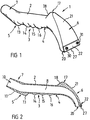
- the scraping tool includes a main component 1 which is integrally cast or moulded of a strong but lightweight material such as a plastics or alloy.
- the component 1 includes an elongate tubular and generally cylindrical handle 2 having a bottom region 3 and front and rear ends 4 and 5 respectively, a head 6 being formed at the front end of the handle 2 and a connector 7 being formed at the rear end of the handle.
- the component 1 is hollow and contains an internal cavity 8 forming a passage which extends continuously through the head 6, the handle 2 and the connector 7.
- the connector 7 shown in the drawings is male, being generally cylindrical and open at its rear end 10 with an upward inclination away from the handle 2.
- the external surface 11 of the connector 7 is slightly tapered for wedging connection with the female end of a vacuum pipe or hose (not shown).
- the connector could be female with a tapered internal surface, or the connector could have an internal or external screw thread for connection with the vacuum hose.
- the illustrated connector could also be coupled with other kinds of vacuum hose fitting via a suitable adaptor.
- a short cylindrical sleeve can be used to connect the tool with a male vacuum hose fitting.
- the lower surface of the connector 7 extends downwardly to form a smooth transversely extending rib 13.
- the bottom region 3 of the handle 2 is formed with three further transversely extending ribs 14, 15 and 16 which are smoothly curved to fit comfortably between the fingers and provide an enhanced grip when the handle 2 is held in the hand.
- the upper region of the handle 2 has an upstanding projection 17, located proximate the junction between the handle 2 and the head 6, forwardly of the foremost rib 16. The surface of the projection 17 is smoothly curved, its rear surface 18 being generally upwardly inclined in a forward direction.
- the front end 4 of the handle 3 leads smoothly into the head 6 which curves downwardly to project below the bottom wall 3 and at the same time progressively becomes narrower in a front-rear direction whilst opening out transversely to terminate in a rectangular slot-shaped opening 20, best seen in Fig. 3.
- the opening 20 extends transverse to the handle and, as seen in Fig. 2, the opening lies on a plane which is generally parallel to the bottom region 3 of the handle 2. It will further be noted in Fig. 2 that the opening 20 is in communication with the internal cavity 8 via the head 6.
- the front surface 21 of the head 6 has a generally triangular shape and is contiguous with the front surface of the projection 17, sloping smoothly forwardly and downwardly towards the opening 20 (Fig.s 1 and 2).
- a hard metal blade 22 is secured to the outside of the head 6 to extend along the front longitudinal margin of opening 20.
- the blade may be formed of tungsten carbide or high speed steel for example and is of generally rectangular shape with the opposed longitudinal edges 23 and 24 of the blade being ground at an angle to the rear surface 25 to form sharp scraping edges 26 and 27.
- the rear surface of the blade 22 is seated against a flat and slightly recessed blade-support area 28 such that the blade is disposed generally perpendicular to the plane of the opening 20, or at a very steep angle thereto.
- the lower scraping edge 27 projects below the plane of the opening 20 extending generally parallel thereto.
- the blade 22 is secured to the head 6 by screws 30 and 31 which pass through non-threaded apertures 32 in the blade 22 to be received in screw-threaded apertures 34 in the head 6. It will be appreciated that the uppermost scraping edge 26 is protected by shoulder 36 formed at the flank of the recessed area 28. However, when the lower edge 27 becomes blunt the screws 30 and 31 can be removed to allow the blade to be rotated and re-secured with the unused sharp edge lowermost.
- a vacuum hose 38 leading from suction apparatus (not shown) is coupled to the connector 7, e.g. by means of a short length of elastomeric tube 39 which forms a double-female coupler to connect with a male hose fitting.
- the hose 38 applies suction to the opening 20 via the internal cavity 8.
- the handle 2 is held in one hand with the fingers located between the ribs 13-16 whilst the other hand is placed on the surface 21 to apply rearward pressure thereto, with the thumb being placed behind the projection 17.
- the opening 20 is moved over a surface to be scraped pulling the blade 22 over the surface in a rearward direction, as indicated by the arrow, at the same time applying pressure to the head via the surface 21.
- the illustrated tool is particularly suitable for removing toxic material from boat hulls it could be used in other applications, e.g. to remove lead-containing paint from a surface.
Landscapes
- Engineering & Computer Science (AREA)
- Mechanical Engineering (AREA)
- Cleaning In General (AREA)
- Knives (AREA)
- Nozzles For Electric Vacuum Cleaners (AREA)
Abstract
Description
Claims (10)
- A hand-held scraping tool characterised by:a handle;a connector for connection with a suction pipe;a head including at least one suction opening in communication with said connector and which, in use, is moved over a surface to be scraped; anda scraping blade mounted on said head.
- A scraping tool according to Claim 1,in which said handle has front and rear ends, said head being mounted at said front end of said handle and said connector being mounted at said rear end of said handle, and said connector being in communication with said at least one opening via an internal passage within said handle.
- A scraping tool according to Claim 1 or 2, in which said blade has a scraping edge which extends transverse to said handle.
- A scraping tool according to any preceding claim, in which said handle has a bottom region and said head projects below said bottom region with said at least one opening disposed proximate the lowermost part of said head.
- A scraping tool according to Claim 4, in which said at least one opening lies on a plane which is substantially parallel with said bottom region.
- A scraping tool according to Claim 4 or 5, in which said blade projects below said lowermost part of said head.
- A scraping tool according to any preceding claim, in which said at least one opening comprises a slot-shaped opening which extends transverse to said handle.
- A scraping tool according to Claim 7, in which said blade extends along a margin of said slot-shaped opening which is remote from said handle.
- A scraping tool according to any preceding claim, in which there is an upstanding projection located proximate the junction between said head and said handle.
- A scraping tool according to Claim 9, in which said upstanding projection has a front face which slopes smoothly downwards in a forward direction to said blade.
Applications Claiming Priority (2)
| Application Number | Priority Date | Filing Date | Title |
|---|---|---|---|
| GBGB9724051.9A GB9724051D0 (en) | 1997-11-15 | 1997-11-15 | Scraping tool |
| GB9724051 | 1997-11-15 |
Publications (2)
| Publication Number | Publication Date |
|---|---|
| EP0919403A2 true EP0919403A2 (en) | 1999-06-02 |
| EP0919403A3 EP0919403A3 (en) | 2002-12-11 |
Family
ID=10822058
Family Applications (1)
| Application Number | Title | Priority Date | Filing Date |
|---|---|---|---|
| EP98309223A Withdrawn EP0919403A3 (en) | 1997-11-15 | 1998-11-11 | Scraping tool |
Country Status (4)
| Country | Link |
|---|---|
| US (1) | US6070292A (en) |
| EP (1) | EP0919403A3 (en) |
| CA (1) | CA2253172A1 (en) |
| GB (2) | GB9724051D0 (en) |
Cited By (1)
| Publication number | Priority date | Publication date | Assignee | Title |
|---|---|---|---|---|
| EP1147733A3 (en) * | 2000-03-09 | 2005-01-05 | Gilberto Cristofori | Method for removing guano from infested spaces and apparatus for carrying out this method |
Families Citing this family (15)
| Publication number | Priority date | Publication date | Assignee | Title |
|---|---|---|---|---|
| DE20104536U1 (en) * | 2001-03-16 | 2001-05-23 | Andreas Stihl AG & Co., 71336 Waiblingen | Hand-held, portable work tool with thumb supports |
| US6601266B1 (en) * | 2001-08-06 | 2003-08-05 | Clifford C. Faraci | Ceiling scraper vacuum accessory |
| US20060200912A1 (en) * | 2005-03-11 | 2006-09-14 | Emerald Innovations Llc | Multipurpose hand-held tool implements |
| USD540994S1 (en) * | 2005-08-19 | 2007-04-17 | James M Borges | Combination scraper vacuum tool |
| US8555463B1 (en) * | 2006-04-18 | 2013-10-15 | Kim E. Laube | Grooming tool with vacuum collection |
| US7805805B2 (en) * | 2006-11-13 | 2010-10-05 | Loveless Ash Company, Inc. | Vacuum assisted scraper |
| US20090067936A1 (en) * | 2007-09-12 | 2009-03-12 | Jonathan Angelisanti | Rasp hand tool and method for using same to form and shape exterior insulation and finish system surfaces |
| US8561303B2 (en) * | 2009-03-01 | 2013-10-22 | Surgical Site Solutions, Inc. | System and method for hair clipping and removal |
| USD659315S1 (en) * | 2011-04-01 | 2012-05-08 | Emerson Electric Co. | Scraper vacuum accessory tool |
| USD725856S1 (en) * | 2014-02-19 | 2015-03-31 | Emerson Electric Co. | Vacuum nozzle with integrated light |
| US9782048B2 (en) | 2015-03-18 | 2017-10-10 | Oneida Air Systems, Inc. | Vacuum assist scraper tool |
| US20160309976A1 (en) * | 2015-04-22 | 2016-10-27 | Nakhonphet Bouphanouvong | Scraping Assembly |
| USD860995S1 (en) * | 2018-01-10 | 2019-09-24 | Zircon Corporation | Handheld scanner |
| USD860994S1 (en) * | 2018-01-10 | 2019-09-24 | Zircon Corporation | Handheld scanner |
| US11433437B2 (en) * | 2018-04-13 | 2022-09-06 | James T. Pierson | Coating removal system |
Family Cites Families (10)
| Publication number | Priority date | Publication date | Assignee | Title |
|---|---|---|---|---|
| US1446854A (en) * | 1918-03-04 | 1923-02-27 | American Radiator Co | Suction cleaning tool |
| US2793384A (en) * | 1952-11-29 | 1957-05-28 | Pauline A Ortega | Cleaning tool for vacuum cleaners |
| US2879530A (en) * | 1955-03-03 | 1959-03-31 | James A Ego | Scraping and cleaning device |
| SU144520A1 (en) * | 1961-05-19 | 1961-11-30 | А.А. Курников | Replaceable Scraper Nozzle |
| US4115892A (en) * | 1977-06-28 | 1978-09-26 | Heinz Stickler | Scraping tool |
| NL8002434A (en) * | 1980-01-25 | 1981-08-17 | Kreutzfeldt & Gregor | SUCTION NOZZLE FOR A VACUUM CLEANER. |
| US4768254A (en) * | 1986-09-29 | 1988-09-06 | Bell David D | Paint scraper tool |
| SE464804B (en) * | 1987-10-07 | 1991-06-17 | Electrolux Ab | HOSE NOZZLE FOR SUCCESSFUL DISSOLUTION AND RESTRICTED SHEET REMAINS |
| US5184372A (en) * | 1991-01-07 | 1993-02-09 | Mache Gerhard R | Vacuum assisted squeegee attachment |
| US5575035A (en) * | 1996-01-24 | 1996-11-19 | Northrop Grumman Corporation | Environmentally sound and safe apparatus for removing coatings |
-
1997
- 1997-11-15 GB GBGB9724051.9A patent/GB9724051D0/en not_active Ceased
-
1998
- 1998-11-06 US US09/187,395 patent/US6070292A/en not_active Expired - Lifetime
- 1998-11-10 CA CA002253172A patent/CA2253172A1/en not_active Abandoned
- 1998-11-11 EP EP98309223A patent/EP0919403A3/en not_active Withdrawn
- 1998-11-13 GB GB9824846A patent/GB2331264B/en not_active Expired - Fee Related
Cited By (1)
| Publication number | Priority date | Publication date | Assignee | Title |
|---|---|---|---|---|
| EP1147733A3 (en) * | 2000-03-09 | 2005-01-05 | Gilberto Cristofori | Method for removing guano from infested spaces and apparatus for carrying out this method |
Also Published As
| Publication number | Publication date |
|---|---|
| CA2253172A1 (en) | 1999-05-15 |
| GB9724051D0 (en) | 1998-01-14 |
| US6070292A (en) | 2000-06-06 |
| GB2331264B (en) | 2001-04-04 |
| EP0919403A3 (en) | 2002-12-11 |
| GB9824846D0 (en) | 1999-01-06 |
| GB2331264A (en) | 1999-05-19 |
Similar Documents
| Publication | Publication Date | Title |
|---|---|---|
| US6070292A (en) | Scraping tool | |
| US5924204A (en) | Scraper tool and blade and method of use | |
| US5437074A (en) | Caulking tool | |
| US5018956A (en) | Caulk and glazing tool | |
| US5095573A (en) | Scraper tool | |
| US3070823A (en) | Fountain-type power lawn mower scraper | |
| EP3459647A1 (en) | Gas-assisted scraping tool | |
| US5072486A (en) | Gas assisted scraper | |
| US20080178393A1 (en) | Multi-function tool apparatus and system | |
| US5490331A (en) | Utility knife for cutting and scraping | |
| US9487188B2 (en) | Tool for removing ice and moisture from a surface | |
| US20080109986A1 (en) | Vacuum Assisted Scraper | |
| US4768254A (en) | Paint scraper tool | |
| US20030159241A1 (en) | Scraper attachment for vacuum cleaners | |
| US4748711A (en) | Ice/snow scraping system | |
| US7263740B2 (en) | Combination squeegee and hand trowel tool | |
| KR20130055656A (en) | Twin bladed scraper tool | |
| WO2013106469A1 (en) | Apparatus and methods for removing material from a surface | |
| US7437794B2 (en) | Magnetic scraper | |
| US4777849A (en) | Packing extractor tool | |
| US20020170134A1 (en) | Scraper with swiveling T-handle | |
| US4849607A (en) | Heat gun assembly with scraper blade cleaning means and method | |
| US20170238776A1 (en) | Device and method for scraping paint off a surface | |
| JP3216973U (en) | Keren tool | |
| JPH11324301A (en) | Scraper for executing interior finish work |
Legal Events
| Date | Code | Title | Description |
|---|---|---|---|
| PUAI | Public reference made under article 153(3) epc to a published international application that has entered the european phase |
Free format text: ORIGINAL CODE: 0009012 |
|
| AK | Designated contracting states |
Kind code of ref document: A2 Designated state(s): AT BE CH CY DE DK ES FI FR GB GR IE IT LI LU MC NL PT SE |
|
| AX | Request for extension of the european patent |
Free format text: AL;LT;LV;MK;RO;SI |
|
| RAP1 | Party data changed (applicant data changed or rights of an application transferred) |
Owner name: PMW ENTERPRISES LIMITED |
|
| PUAL | Search report despatched |
Free format text: ORIGINAL CODE: 0009013 |
|
| AK | Designated contracting states |
Kind code of ref document: A3 Designated state(s): AT BE CH CY DE DK ES FI FR GB GR IE IT LI LU MC NL PT SE |
|
| AX | Request for extension of the european patent |
Free format text: AL;LT;LV;MK;RO;SI |
|
| RIC1 | Information provided on ipc code assigned before grant |
Free format text: 7B 44D 3/16 A, 7A 47L 13/08 B |
|
| 17P | Request for examination filed |
Effective date: 20030507 |
|
| AKX | Designation fees paid |
Designated state(s): DE ES FR GB NL |
|
| 17Q | First examination report despatched |
Effective date: 20040125 |
|
| STAA | Information on the status of an ep patent application or granted ep patent |
Free format text: STATUS: THE APPLICATION IS DEEMED TO BE WITHDRAWN |
|
| 18D | Application deemed to be withdrawn |
Effective date: 20050601 |