EP0919507A2 - Fahrtreppe mit Betriebsbremse - Google Patents
Fahrtreppe mit Betriebsbremse Download PDFInfo
- Publication number
- EP0919507A2 EP0919507A2 EP98119232A EP98119232A EP0919507A2 EP 0919507 A2 EP0919507 A2 EP 0919507A2 EP 98119232 A EP98119232 A EP 98119232A EP 98119232 A EP98119232 A EP 98119232A EP 0919507 A2 EP0919507 A2 EP 0919507A2
- Authority
- EP
- European Patent Office
- Prior art keywords
- braking
- arrangement
- braking torque
- spring
- escalator according
- Prior art date
- Legal status (The legal status is an assumption and is not a legal conclusion. Google has not performed a legal analysis and makes no representation as to the accuracy of the status listed.)
- Granted
Links
- 238000013016 damping Methods 0.000 claims description 9
- 230000000694 effects Effects 0.000 claims description 5
- 230000007423 decrease Effects 0.000 claims description 4
- 230000002829 reductive effect Effects 0.000 claims description 3
- 238000011161 development Methods 0.000 description 7
- 230000018109 developmental process Effects 0.000 description 7
- 238000000034 method Methods 0.000 description 6
- 238000013461 design Methods 0.000 description 3
- 230000002123 temporal effect Effects 0.000 description 2
- 238000012549 training Methods 0.000 description 2
- 238000009423 ventilation Methods 0.000 description 2
- 230000006978 adaptation Effects 0.000 description 1
- 230000000712 assembly Effects 0.000 description 1
- 238000000429 assembly Methods 0.000 description 1
- 230000033228 biological regulation Effects 0.000 description 1
- 238000010276 construction Methods 0.000 description 1
- 230000003247 decreasing effect Effects 0.000 description 1
- 230000001419 dependent effect Effects 0.000 description 1
- 230000000670 limiting effect Effects 0.000 description 1
- 238000004519 manufacturing process Methods 0.000 description 1
- 238000012986 modification Methods 0.000 description 1
- 230000004048 modification Effects 0.000 description 1
- 230000036961 partial effect Effects 0.000 description 1
- 230000036316 preload Effects 0.000 description 1
- 239000000725 suspension Substances 0.000 description 1
- 230000036962 time dependent Effects 0.000 description 1
Images
Classifications
-
- B—PERFORMING OPERATIONS; TRANSPORTING
- B66—HOISTING; LIFTING; HAULING
- B66B—ELEVATORS; ESCALATORS OR MOVING WALKWAYS
- B66B23/00—Component parts of escalators or moving walkways
- B66B23/02—Driving gear
Definitions
- the invention relates to an escalator with a service brake according to the preamble of claim 1 and in particular one Escalator service brake with increasing braking torque.
- one known embodiment has two stacked double shoe brakes with a total of four brake shoes, with a double shoe brake as Service brake and the other is used as an additional brake.
- the known braking devices have in common that they are The type and design can only be used inflexibly. So is in depending on the delivery head, direction and speed Escalators, for example, one specified on these parameters Brake arrangement required.
- the invention has for its object an improved Braking device according to the preamble of claim 1 to create flexible use, improved security guaranteed for escalator users, inexpensive is producible and better suited to the respective braking requirements can be adjusted.
- an escalator with a service brake with which service brake a braking force on the in Movement step band or a braking torque at least one shaft coupled to the moving step belt can be applied, the braking torque and / or the braking force is at least partially variable during the braking period.
- the preamble according to claim 1 is mainly here understood a moving walk or an escalator, the invention basically also with any other funding institutions can be used.
- the service brake according to the invention enables e.g. an adjustment of the braking behavior with different Loads the escalator, the setting of a load-independent Braking distance, setting a load-dependent or load-independent delay as well as a Variation of the delay, for example in such a way that this in the initial phase of the braking period is less.
- An escalator according to the invention is also advantageous in that as an optimal regardless of their direction Braking behavior can be set.
- this generates accordingly executed brake assembly a substantially predetermined Initial braking torque and then increases the braking torque during the braking period to a maximum value.
- the braking torque curve can increase both monotonously also as a combination of monotonous and strictly monotonously increasing be designed.
- This embodiment according to the invention is useful in so far as people standing on the moving step belt not from an abrupt braking are surprised and consequently as a result their inertia plummet.
- the People but also the possibility or time on the Braking to respond, for example, their Shift focus and thus a more stable to the Braking can adopt adjusted position. Through the Invention thus significantly reduces the risk of accidents.
- the service brake comprises a main spring assembly, by the spring force during the Braking period a braking torque on with the service brake coupled shaft is caused, an additional spring arrangement, whose spring force opposes that of the main spring arrangement, is lower, however, and a damper arrangement, those with the additional spring arrangement essentially in series is switched.
- Such an arrangement of spring assemblies and damper assembly allows that through the main spring assembly generated braking torque during the braking period - as a result of developing force in the additional spring arrangement - initially is reduced, i.e. a relatively low braking torque in the Initial phase of the braking time is applied. Subsequently the additional spring arrangement relaxes by time-dependent The damper becomes ineffective.
- the effective braking torque increases slowly because the force counteracting the spring force of the main spring arrangement the additional spring arrangement decreases damped, the additional spring arrangement the force introduced by the main spring assembly can partially avoid.
- This training is advantageous in that it is easier Construction with simple robust components that are not depend on a functioning power supply - what in Dangerous situations that are linked to a power failure are necessary is - enables a gentle braking process. By the waiver of electrical or electromagnetic components this version is also energy-saving.
- Such a braking device according to the invention shows the surprising advantage that the braking distance is only slightly changes compared to known devices.
- Part of the additional spring arrangement can also be parallel to the Damper arrangement be switched. This is an example such that this part - at least partially - can be switched off, so that this also can set the maximum achievable braking torque.
- an intermediate device is loaded with pressure and which is based on the Additional spring arrangement connecting the intermediate device unloaded, under pressure.
- the start-up phase of the To determine braking This is done at the beginning of the braking process due to the spring force of the main spring assembly Spring force of the intermediate spring assembly built.
- the initial braking torque is the pressurized, preloaded state less because the damper arrangement of the spring force counteracts the main spring arrangement.
- the Damping of the damper arrangement selected such that the Damper arrangement is only effective when additional spring arrangement has traveled a predetermined distance and / or with a predetermined distance Minimum force is loaded.
- control device for variable, controlled setting of the identifier of the Additional spring arrangement and / or the damping of the damper arrangement and / or the braking torque and / or the deceleration of the moving step belt provided.
- the control device is to be understood here broadly and includes in particular a control device.
- the possibility is thus created about the control process according to the invention, which itself in a time dependence on the size of the generated Braking torque expresses to intervene to control that the braking torque curve can be set variably.
- This setting can also be made at a standstill and thus for a subsequent braking process can be predefined as it can take place during operation, the latter Variation in particular also to adapt to changed Operating conditions, e.g. changed loads of the moving Step band, offers. This always makes sense Braking process guaranteed.
- the braking distance through the control device as well Onset of the braking period can be predetermined as well Cyclical recording of the braking distance already covered Damper arrangement adjusted during the braking period can be that the braking distance is always constant.
- This training is advantageous in that it Use one and the same brake arrangement for different loaded step belt and at different delivery heights enables what is also a more economical production process enabled due to higher quantities. Furthermore, the starting point during operation of an escalator as well the damping of the damper assembly can be varied so that always an optimal adaptation to the operation of the escalator changing parameters (e.g. the load on the step belt) is possible and therefore always optimal braking behavior is ensured.
- the damping of the damper assembly can be varied so that always an optimal adaptation to the operation of the escalator changing parameters (e.g. the load on the step belt) is possible and therefore always optimal braking behavior is ensured.
- control device as well as the main spring and / or secondary spring arrangement procure that the spring constant of the respective spring arrangement is variably adjustable.
- the size of the initial braking torque is thus made possible according to the invention set and the following braking torque curve to influence.
- the Obtain and arranged control device such that a predetermined braking distance of the moving step belt (e.g. load or constant braking distance regardless of speed) can be.
- a predetermined braking distance of the moving step belt e.g. load or constant braking distance regardless of speed
- control device that a predetermined deceleration of the moving step belt, such as a constant deceleration independent of load or speed, can be set can be useful.
- a further development of the invention has a measuring device for measuring the load and / or the speed of the step band.
- the respective load or speed state of the Step band are recorded and the data recorded Control device are supplied. This enables in Combination with the control device that when braking an optimal braking torque is always generated.
- Measuring device makes sense. For example, also for control of the escalator drive.
- control device is also useful such that the damping of the damper assembly is always in operation the load and / or the state of movement of the Step band is adjusted so that a predetermined Braking torque and / or a predetermined deceleration always is ensured.
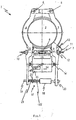
- a brake assembly according to the invention 1 one with the escalator drive, not shown Coupled, rotatably mounted shaft 2 (e.g. main shaft with chain wheels for driving the step belt), whose Speed in the operation of the escalator the speed of the Step band represents.
- shaft 2 e.g. main shaft with chain wheels for driving the step belt
- each of the spring rod ends 10 arranged, for example via an intermediate Washer 12 a main spring assembly (brake spring) 13, the their second end against the outside of the braking period in essentially rotatably fixed brake shoe 3, 4 is mounted, loaded on pressure (before).
- a main spring assembly brake spring 13
- the preload of the main spring assembly vary, so that the braking torque and thus the Braking distance is adjustable.
- a brake ventilation device 14 with brake release lever 15 arranged on the brake shoes 3, 4th facing ends each adjusting nuts 16 for adjustment of the brake shoe stroke are arranged.
- the cylinder of the damper arrangement 18 stands with a first one Brake shoe 3 in firm, but adjustable contact, see above that the position of the damper assembly 18 move axially leaves.
- the extension of the damper arrangement stands with one Linkage 19 in contact, which is in the axial extension of the Damper arrangement 18 from an opening of the second brake shoe 4 is axially displaceable. With the linkage 19 is a fixing washer 20 firmly connected.
- the additional spring assembly 17 extends coaxially around the Linkage 19 around and has a between the second brake shoe 4th and fixing disc 20 arranged first spring 21 and a second arranged between the fixing plate 20 and the extension Spring 22 on which the damper (18) in its unloaded Starting position.
- Braking is carried out by the de-energized brake release magnet 14 initiated.
- brake shoes 3 and 4 must be used immediately occur, which is caused by the preloaded springs 13 is so that the shaft 2 is braked.
Landscapes
- Escalators And Moving Walkways (AREA)
- Braking Arrangements (AREA)
Abstract
Description
- Fig. 1
- eine schematische Ansicht einer beispielhaften erfindungsgemäßen Ausführungsform.
Claims (12)
- Fahrtreppe mit einer Betriebsbremse (1) zum Abbremsen des Stufenbandes, durch die eine Bremskraft auf die Motorwelle (2) und/oder ein Bremsmoment auf mindestens eine mit dem Stufenband gekoppelte Welle aufbringbar ist, dadurch gekennzeichnet, daß ein mindestens während eines Zeitraums im Verlauf einer Bremsung variables Bremsmoment der Betriebsbremse vorgesehen ist.
- Fahrtreppe nach Anspruch 1, dadurch gekennzeichnet, daß die Betriebsbremse (1) derart beschaffen und angeordnet ist, daß das Bremsmoment auf einen im wesentlichen vorbestimmten Anfangswert eingestellt wird und dann während der Betätigung der Bremsvorrichtung mit fortschreitender Zeit im wesentlichen zunimmt.
- Fahrtreppe nach einem der vorhergehenden Ansprüche, gekennzeichnet durcheine Hauptfederanordnung (13), mit deren Federkraft ein Bremsmoment auf die Motorwelle (2) aufbringbar ist;einer Zusatzfederanordnung (17), mit deren Federkraft das von der Hauptfederanordnung (13) hervorgerufene Bremsmoment verminderbar ist; undeiner Dämpferanordnung (18), die mit der Zusatzfederanordnung (17) im wesentlichen in Reihe geschaltet ist.
- Fahrtreppe nach einem der vorhergehenden Ansprüche, dadurch gekennzeichnet, daß im ungebremsten Zustand des bewegten Stufenbandesdie Hauptfederanordnung (13) durch einen aktivierten Bremslüft-Spreizmagneten (14) druckbelastet ist; unddie Zusatzfederanordnung (17) sich an den Bremslüftmagneten (14) unbelastet oder auf Druck belastet anschließt.
- Fahrtreppe nach einem der vorhergehenden Ansprüche, dadurch gekennzeichnet, daß die Dämpfung der Dämpferanordnung (18) derart auf die Federkonstante der Zusatzfederanordnung (17) abgestimmt ist, daß die Dämpferanordnung (18) die Zeit bestimmt, in der Feder (21) vollständig entspannt wird.
- Fahrtreppe nach einem der vorhergehenden Ansprüche, gekennzeichnet durch eine Steuervorrichtung zur gesteuerten, variablen Einstellung der Kennung der Zusatzfederanordnung (17) und/oder der Dämpfung der Dämpferanordnung (18) und/oder des Bremsmoments und/oder der Verzögerung des bewegten Stufenbandes.
- Fahrtreppe nach einem der vorhergehenden Ansprüche, dadurch gekennzeichnet, daß unter Steuerung der Steuervorrichtung sowie der Dämpferanordnung (18) beim Ansprechen der Bremse die Wirkung der Dämpferanordnung (18) am größten ist und anschließend abnimmt, so daß das Bremsmoment zunimmt, und/oder die Dämpfung der Dämpferanordnung (18) variabel einstellbar ist.
- Fahrtreppe nach einem der vorhergehenden Ansprüche, dadurch gekennzeichnet, daß die Steuervorrichtung sowie die Hauptfeder- und/oder Nebenfederanordnung derart beschaffen sind, daß die Federkonstante der jeweiligen Federanordnung einstellbar ist.
- Fahrtreppe nach einem der vorhergehenden Ansprüche, dadurch gekennzeichnet, daß mit der Steuervorrichtung ein vorbestimmter Bremsweg des Stufenbandes, wie ein last- oder geschwindigkeitsunabhängig konstanter Bremsweg, einstellbar ist.
- Fahrtreppe nach einem der vorhergehenden Ansprüche, dadurch gekennzeichnet, daß mit der Steuervorrichtung eine vorbestimmte Verzögerung des Stufenbandes, wie eine last- oder geschwindigkeitsunabhängig konstante Verzögerung, einstellbar ist.
- Fahrtreppe nach einem der vorhergehenden Ansprüche, gekennzeichnet durch eine Meßvorrichtung zur Messung der Belastung und/oder der Geschwindigkeit des Stufenbandes.
- Fahrtreppe nach einem der vorhergehenden Ansprüche, dadurch gekennzeichnet, daß mit der Steuervorrichtung die Dämpfung der Dämpferanordnung (18) im Betrieb stets an die Belastung und/oder den Bewegungszustand des Stufenbandes zur Sicherstellung eines vorbestimmten Bremsmoments und/oder einer vorbestimmten Verzögerung anpaßbar ist.
Applications Claiming Priority (2)
| Application Number | Priority Date | Filing Date | Title |
|---|---|---|---|
| DE29719565U | 1997-11-04 | ||
| DE29719565U DE29719565U1 (de) | 1997-11-04 | 1997-11-04 | Fahrtreppe mit Betriebsbremse |
Publications (3)
| Publication Number | Publication Date |
|---|---|
| EP0919507A2 true EP0919507A2 (de) | 1999-06-02 |
| EP0919507A3 EP0919507A3 (de) | 1999-06-16 |
| EP0919507B1 EP0919507B1 (de) | 2005-11-16 |
Family
ID=8048149
Family Applications (1)
| Application Number | Title | Priority Date | Filing Date |
|---|---|---|---|
| EP98119232A Expired - Lifetime EP0919507B1 (de) | 1997-11-04 | 1998-10-12 | Fahrtreppe mit Betriebsbremse |
Country Status (3)
| Country | Link |
|---|---|
| EP (1) | EP0919507B1 (de) |
| AT (1) | ATE309954T1 (de) |
| DE (2) | DE29719565U1 (de) |
Families Citing this family (2)
| Publication number | Priority date | Publication date | Assignee | Title |
|---|---|---|---|---|
| CN106050997A (zh) * | 2016-07-11 | 2016-10-26 | 宁波宏大电梯有限公司 | 一种制动结构及扶梯主机 |
| DE102023110190A1 (de) * | 2023-04-21 | 2024-10-24 | Tk Elevator Innovation And Operations Gmbh | Verfahren zum Bremsen eines Stufen- oder Palettenbands einer Personenbeförderungsanlage |
Family Cites Families (4)
| Publication number | Priority date | Publication date | Assignee | Title |
|---|---|---|---|---|
| US3830344A (en) * | 1973-02-15 | 1974-08-20 | Reliance Electric Co | Brake and control therefor |
| US4231452A (en) * | 1978-12-28 | 1980-11-04 | Westinghouse Electric Corp. | Spring applied, electric released drum brake |
| JPH05139678A (ja) * | 1991-11-22 | 1993-06-08 | Toshiba Corp | マンコンベアのブレーキ装置 |
| US5337878A (en) * | 1993-12-28 | 1994-08-16 | Otis Elevator Company | Assembly and method for adjusting brake force for passenger conveyor emergency brake |
-
1997
- 1997-11-04 DE DE29719565U patent/DE29719565U1/de not_active Expired - Lifetime
-
1998
- 1998-10-12 DE DE59813194T patent/DE59813194D1/de not_active Expired - Fee Related
- 1998-10-12 AT AT98119232T patent/ATE309954T1/de not_active IP Right Cessation
- 1998-10-12 EP EP98119232A patent/EP0919507B1/de not_active Expired - Lifetime
Also Published As
| Publication number | Publication date |
|---|---|
| EP0919507B1 (de) | 2005-11-16 |
| DE59813194D1 (de) | 2005-12-22 |
| ATE309954T1 (de) | 2005-12-15 |
| EP0919507A3 (de) | 1999-06-16 |
| DE29719565U1 (de) | 1998-02-19 |
Similar Documents
| Publication | Publication Date | Title |
|---|---|---|
| DE2921064C2 (de) | Elektromagnetisch lüftbare Federdruckbremse zum Abbremsen einer Welle | |
| DE102010023700B4 (de) | Stellvorrichtung für eine selbstverstärkende Bremseinrichtung und selbstverstärkende Bremseinrichtung | |
| EP2531742B1 (de) | Druckstangensteller für kompakt-bremszangeneinheiten mit gegen einen elastischen anschlag anschlagbarem stellhebel | |
| DE202011110405U1 (de) | Bremsbetätigungsmechanismus für eine Scheibenbremse | |
| EP2307754B1 (de) | Nachstellvorrichtung für eine scheibenbremse | |
| EP0899147A1 (de) | Fahrpedal mit Dämpfungseinrichtung | |
| EP2989344B1 (de) | Scheibenbremse mit einer bidirektionalen verschleissnachstellvorrichtung, und bidirektionale verschleissnachstellvorrichtung | |
| DE19851668A1 (de) | Radbremsvorrichtung | |
| DE2438460C2 (de) | Mechanisch betätigte Scheibenbremse | |
| DE102013201635A1 (de) | Bremseinheit für ein Fahrzeug und Fahrzeug mit einer derartigen Bremseinheit | |
| EP3883875A1 (de) | Geschwindigkeitsbegrenzer für ein hebezeug mit fliehkraftbetätigter bremse | |
| DE1555652B2 (de) | Selbsttaetige nachstellvorrichtung fuer die hydraulische betaetigungsvorrichtung einer fahrzeugbremse | |
| DE102010023699B4 (de) | Selbstverstärkende Bremseinrichtung | |
| DE2836740A1 (de) | Mehrfach-scheibenbremsenanordnung fuer ein flugzeug | |
| DE102010023701A1 (de) | Lüftgerät für eine Bremseinrichtung | |
| WO2018015087A1 (de) | Fahrzeugbetriebsbremse mit elektromechanisch-hydraulischer bremskraftverstärkung | |
| DE69102746T2 (de) | Elektromechanische Steuerung mit Hilfe einer Zentrifuge. | |
| DE2506186A1 (de) | Nachstellvorrichtung fuer eine fahrzeugbremse | |
| DE19747114B4 (de) | Elektromagnetisch betätigte Scheibenbremse für Hublader | |
| EP0919507B1 (de) | Fahrtreppe mit Betriebsbremse | |
| DE8811920U1 (de) | Mechanische Betätigungsvorrichtung für eine Radbremse eines Kraftfahrzeuges | |
| EP0857686B1 (de) | Fahrtreppe | |
| DE102008006481A1 (de) | Scheibenbremse für ein Nutzfahrzeug | |
| EP3867544B1 (de) | Scheibenbremse | |
| EP2422106A1 (de) | Mehrscheibenbremse |
Legal Events
| Date | Code | Title | Description |
|---|---|---|---|
| PUAI | Public reference made under article 153(3) epc to a published international application that has entered the european phase |
Free format text: ORIGINAL CODE: 0009012 |
|
| PUAL | Search report despatched |
Free format text: ORIGINAL CODE: 0009013 |
|
| AK | Designated contracting states |
Kind code of ref document: A2 Designated state(s): AT CH DE ES FR GB LI |
|
| AX | Request for extension of the european patent |
Free format text: AL;LT;LV;MK;RO;SI |
|
| AK | Designated contracting states |
Kind code of ref document: A3 Designated state(s): AT BE CH CY DE DK ES FI FR GB GR IE IT LI LU MC NL PT SE |
|
| AX | Request for extension of the european patent |
Free format text: AL;LT;LV;MK;RO;SI |
|
| RIC1 | Information provided on ipc code assigned before grant |
Free format text: 6B 66B 23/02 A, 6B 66B 29/00 B, 6B 66D 5/08 B |
|
| 17P | Request for examination filed |
Effective date: 19990802 |
|
| AKX | Designation fees paid |
Free format text: AT CH DE ES FR GB LI |
|
| RAP1 | Party data changed (applicant data changed or rights of an application transferred) |
Owner name: THYSSEN FAHRTREPPEN GMBH |
|
| 17Q | First examination report despatched |
Effective date: 20041008 |
|
| GRAP | Despatch of communication of intention to grant a patent |
Free format text: ORIGINAL CODE: EPIDOSNIGR1 |
|
| GRAS | Grant fee paid |
Free format text: ORIGINAL CODE: EPIDOSNIGR3 |
|
| GRAA | (expected) grant |
Free format text: ORIGINAL CODE: 0009210 |
|
| AK | Designated contracting states |
Kind code of ref document: B1 Designated state(s): AT CH DE ES FR GB LI |
|
| REG | Reference to a national code |
Ref country code: GB Ref legal event code: FG4D Free format text: NOT ENGLISH |
|
| REG | Reference to a national code |
Ref country code: CH Ref legal event code: EP |
|
| REF | Corresponds to: |
Ref document number: 59813194 Country of ref document: DE Date of ref document: 20051222 Kind code of ref document: P |
|
| PG25 | Lapsed in a contracting state [announced via postgrant information from national office to epo] |
Ref country code: ES Free format text: LAPSE BECAUSE OF FAILURE TO SUBMIT A TRANSLATION OF THE DESCRIPTION OR TO PAY THE FEE WITHIN THE PRESCRIBED TIME-LIMIT Effective date: 20060227 |
|
| GBT | Gb: translation of ep patent filed (gb section 77(6)(a)/1977) |
Effective date: 20060223 |
|
| ET | Fr: translation filed | ||
| PLBE | No opposition filed within time limit |
Free format text: ORIGINAL CODE: 0009261 |
|
| STAA | Information on the status of an ep patent application or granted ep patent |
Free format text: STATUS: NO OPPOSITION FILED WITHIN TIME LIMIT |
|
| 26N | No opposition filed |
Effective date: 20060817 |
|
| PG25 | Lapsed in a contracting state [announced via postgrant information from national office to epo] |
Ref country code: LI Free format text: LAPSE BECAUSE OF NON-PAYMENT OF DUE FEES Effective date: 20061031 Ref country code: CH Free format text: LAPSE BECAUSE OF NON-PAYMENT OF DUE FEES Effective date: 20061031 |
|
| REG | Reference to a national code |
Ref country code: CH Ref legal event code: PL |
|
| REG | Reference to a national code |
Ref country code: FR Ref legal event code: ST Effective date: 20080630 |
|
| PGFP | Annual fee paid to national office [announced via postgrant information from national office to epo] |
Ref country code: FR Payment date: 20061020 Year of fee payment: 9 |
|
| PGFP | Annual fee paid to national office [announced via postgrant information from national office to epo] |
Ref country code: DE Payment date: 20080923 Year of fee payment: 11 |
|
| PGFP | Annual fee paid to national office [announced via postgrant information from national office to epo] |
Ref country code: AT Payment date: 20081023 Year of fee payment: 11 |
|
| PG25 | Lapsed in a contracting state [announced via postgrant information from national office to epo] |
Ref country code: FR Free format text: LAPSE BECAUSE OF NON-PAYMENT OF DUE FEES Effective date: 20071031 |
|
| PGFP | Annual fee paid to national office [announced via postgrant information from national office to epo] |
Ref country code: GB Payment date: 20081027 Year of fee payment: 11 |
|
| PG25 | Lapsed in a contracting state [announced via postgrant information from national office to epo] |
Ref country code: DE Free format text: LAPSE BECAUSE OF NON-PAYMENT OF DUE FEES Effective date: 20100501 |
|
| PG25 | Lapsed in a contracting state [announced via postgrant information from national office to epo] |
Ref country code: AT Free format text: LAPSE BECAUSE OF NON-PAYMENT OF DUE FEES Effective date: 20091012 |
|
| PG25 | Lapsed in a contracting state [announced via postgrant information from national office to epo] |
Ref country code: GB Free format text: LAPSE BECAUSE OF NON-PAYMENT OF DUE FEES Effective date: 20091012 |