EP0919724A2 - Hydraulisch angetriebene Doppelmembranpumpe - Google Patents
Hydraulisch angetriebene Doppelmembranpumpe Download PDFInfo
- Publication number
- EP0919724A2 EP0919724A2 EP98830707A EP98830707A EP0919724A2 EP 0919724 A2 EP0919724 A2 EP 0919724A2 EP 98830707 A EP98830707 A EP 98830707A EP 98830707 A EP98830707 A EP 98830707A EP 0919724 A2 EP0919724 A2 EP 0919724A2
- Authority
- EP
- European Patent Office
- Prior art keywords
- oil
- pumping
- suction
- tank
- units
- Prior art date
- Legal status (The legal status is an assumption and is not a legal conclusion. Google has not performed a legal analysis and makes no representation as to the accuracy of the status listed.)
- Granted
Links
- 238000005086 pumping Methods 0.000 claims abstract description 51
- 239000012530 fluid Substances 0.000 claims abstract description 24
- 239000007788 liquid Substances 0.000 claims abstract description 14
- 239000000126 substance Substances 0.000 claims abstract description 9
- 230000033001 locomotion Effects 0.000 claims abstract description 6
- 239000003921 oil Substances 0.000 claims description 48
- 238000006073 displacement reaction Methods 0.000 claims description 8
- 238000000034 method Methods 0.000 claims description 7
- 230000008569 process Effects 0.000 claims description 7
- 230000010349 pulsation Effects 0.000 claims description 5
- 230000010363 phase shift Effects 0.000 claims description 3
- 230000009467 reduction Effects 0.000 claims description 3
- 239000010720 hydraulic oil Substances 0.000 claims description 2
- 230000009471 action Effects 0.000 description 6
- 238000010586 diagram Methods 0.000 description 5
- 238000010276 construction Methods 0.000 description 3
- 238000000926 separation method Methods 0.000 description 2
- 238000010521 absorption reaction Methods 0.000 description 1
- 230000005540 biological transmission Effects 0.000 description 1
- 230000001419 dependent effect Effects 0.000 description 1
- 230000008030 elimination Effects 0.000 description 1
- 238000003379 elimination reaction Methods 0.000 description 1
- 230000009347 mechanical transmission Effects 0.000 description 1
- 238000012986 modification Methods 0.000 description 1
- 230000004048 modification Effects 0.000 description 1
- 230000000737 periodic effect Effects 0.000 description 1
- 230000001681 protective effect Effects 0.000 description 1
Images


Classifications
-
- F—MECHANICAL ENGINEERING; LIGHTING; HEATING; WEAPONS; BLASTING
- F04—POSITIVE - DISPLACEMENT MACHINES FOR LIQUIDS; PUMPS FOR LIQUIDS OR ELASTIC FLUIDS
- F04B—POSITIVE-DISPLACEMENT MACHINES FOR LIQUIDS; PUMPS
- F04B43/00—Machines, pumps, or pumping installations having flexible working members
- F04B43/02—Machines, pumps, or pumping installations having flexible working members having plate-like flexible members, e.g. diaphragms
- F04B43/06—Pumps having fluid drive
- F04B43/073—Pumps having fluid drive the actuating fluid being controlled by at least one valve
- F04B43/0733—Pumps having fluid drive the actuating fluid being controlled by at least one valve with fluid-actuated pump inlet or outlet valves; with two or more pumping chambers in series
Definitions
- the present invention relates to a device for pumping liquids or aeriform substances, with double-acting reciprocating motion obtained hydraulically.
- Liquid and aeriform pumping systems can be substantially subdivided into two classes: (a) fluid dynamic action systems, such as for example centrifugal pumps and the like, based on the laws of fluid dynamics and on the transfer between the momentum and the mechanical energy, and (b) positive-displacement systems, based on the variation of the volume enclosed in a pump casing by both direct and indirect mechanical action by means of a working fluid.
- fluid dynamic action systems such as for example centrifugal pumps and the like
- positive-displacement systems based on the variation of the volume enclosed in a pump casing by both direct and indirect mechanical action by means of a working fluid.
- the present invention relates to a device for pumping liquids or aeriform substances of the above-mentioned type, which is included in the system class of the(b) group indicated above.
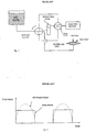
- Said device is schematized in the annexed figure 1, and it is a reciprocating positive displacement pumping system indirectly operated by a fluid (oil) pressurized in a continuous way by means of a rotary positive displacement pump, in particular a gear pump which cooperates by means of a mechanical transmission of the same driving force which operates the pump, with a rotary valve which reverses the oil flow between the reciprocating pumping unit and a tank.
- Figure 2 shows the behavior, as a function of time, of the flow rate of a pumping system such as the one showed in figure 1 according to the Italian patent No 1,262,358 previously referred to.
- the pumping action is of a pulsating type, and the flow rate or delivery is similar to a square wave.
- the pulsation is due to the fact that the diaphragm pumping unit (figure 1) is of the single acting type, and corresponds to the electrical analogy of a single half-wave rectifier.
- Such pulsating behavior can suit numerous applications, but. in the case of high flow rates and pressures the pulsation of the pumped fluid, be it a liquid or an aeriform substance, may involve many problems such as periodic stresses in the system fed by the pump, with possible drawbacks due to fatigue stress of the components, noise and flow discontinuity which can prove harmful to refrigerators or heat pumps operating on an absorption cycle, as it is well-known to a man skilled in the art.
- the aim of the present invention is to provide a device for pumping liquids or aeriform substances with a double-acting reciprocating motion or action, with diaphragm pumping units, or the like, of the class described in the above-mentioned Italian patent.
- a pumping system of the type being discussed which comprises at least two pumping units, provided with a separating element which is formed by a diaphgram or the like, said pumping units being operated by a pressurized hydraulic fluid (oil), and working in a push-pull manner so as to obtain a double-acting pumping action and a substantial elimination of fluctuations in the flow rate and/or pressure at the outlet side of the pumping system, wherein the fluid of said two diaphragm pumping units is combined by means of a valve assembly, in a similar way to what is known in electrotechnics as "Graetz bridge", according to which the outlet flow of the pumping system is practically continuous and free from unwanted pulsations, particularly as regards liquids.
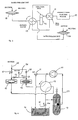
- An oil control assembly which comprises a prime motor consisting of an electric motor 10 which operates a positive displacement rotary pump 11, in particular a gear pump, to move a driving fluid (oil).
- the transmission of mechanical operation by gear pump 11 through a reduction gear 12 operates a rotary valve 13 which supplies or withdraws oil from a first diaphragm pumping unit 14 and from a second diaphragm pumping unit 15.
- the circuit of the oil which is the working fluid, and the arrangement of the ways of the rotary valve 13 imply a push-pull working of the pumping units 14 and 15, that is a 180° phase shift between the flow rate/pressure pulsations generated in the pumped fluid.
- the "voids" shown in the schematization of the operative modes of the single-acting pumping system of figure 2 are eliminated.
- a tank 16, not pressurized is provided, which, in order to compensate the expansion of the working fluid (oil), operates like an expansion tank, wherein the excess pressure from the pump 11 is discharged by means of a calibrated overpressure or safety valve 17.
- Makeup oil can be withdrawn from the tank or expansion tank by means of a valve 18 which can be suitably calibrated, in order to prevent short circuits at the oil side during intake at low pressures.
- This valve 18 is calibrated at a suitably low pressure to allow the suction of fluids at pressures equal or higher than the calibration pressure.
- the pipe coming from the valve 18, together with the oil intake line at the side of the diaphragm units 14, 15 leads to tank 19 wherein a filter F is possibly located, which has an outlet 20 connected to the intake side of the gear pump 11.
- An assembly of unidirectional valves 21, 22,23,24 in the configuration which is well known in electronics as "Graetz bridge", is located on the process side of the diaphragm pumping units 14,15.
- the valves 21,22,23,24 are respectively connected to suction 25 and delivery 26 pipes.
- figure 5 a second variant of the practical embodiment of figure 4 is shown.
- a further safety valve 27, which is calibrated at a lower pressure than safety valve 17, can be provided on the delivery side of the pump 11.
- the valve 27 is closed during the normal operation of the system, while, on the contrary, it is used during the first minutes of the system startup only to allow the discharge of the possible excess oil let into the charge, together with the one resulting from the thermal expansion at the normal operating temperature.
- the variant of figure 6 corresponds to the one of figure 5.
- the tank is partially full and the free space 28 over the oil mass serves as an expansion space to compensate the thermal expansions of the oil.
- FIG. 7 A further embodiment is shown in figure 7, corresponding in part to the one in figure 6.
- the pressure on the intake side of the diaphragm pumping units will have to be higher than the atmospheric pressure at least by the value required to overcome the elasticity of the diaphragm added to the pressure losses on the oil side. Otherwise, as it is evident, no pumping action would take place.
- a diaphragm expansion tank 30 in the circuit of the working oil, is provided, only partially filled with oil.
- the diaphragm expansion tank 30 allows the thermal expansion of the oil by means of the discharge valve, while the calibrated makeup valve allows the normal pumping with intake of oil from the diaphragm units and, only for makeup, also from the expansion tank.
- the expansion tank 30 is connected on the side opposite to the oil side, to the intake pipe on the process side, so as to cause the makeup pressure of the makeup valve to adjust automatically to the intake pressure on the process side, hence eliminating the occurrence of short-circuits on the oil side.
- the oil circuit remains sealed on the environment side in order to prevent leaks of harmful substances in case of a break of the pumping units' diaphragms.
- Said separation between the oil and the process fluid can be obtained, as it is known to a man skilled in the art, by means of elastic seals between the cylinder and the piston with or without the aid of a so-called "lantern” separating the cylinder on the process side from the cylinder on the oil side.
- the free-piston pumping unit comprises a cylinder 40 inside which a piston 41, kept sealed by seals 42, can slide.
- the piston 41 defines a first control chamber 43 wherein a working fluid (oil) can be forwarded and withdrawn by means of a line 44, and a second working or positive displacement pumping chamber 45, which cooperates with a delivery valve 46 and a suction valve 47.
- the valves 46, 47 are respectively shown as unidirectional valves of the ball type with a conical seat, however, it is clear that they can be of other shapes.
Landscapes
- Engineering & Computer Science (AREA)
- Mechanical Engineering (AREA)
- General Engineering & Computer Science (AREA)
- Reciprocating Pumps (AREA)
Applications Claiming Priority (2)
| Application Number | Priority Date | Filing Date | Title |
|---|---|---|---|
| ITRM970739 | 1997-11-28 | ||
| IT97RM000739A IT1297087B1 (it) | 1997-11-28 | 1997-11-28 | Dispositivo per il pompaggio di liquidi o aeriformi, con moto alternativo a doppio effetto ottenuto per via idraulica. |
Publications (3)
| Publication Number | Publication Date |
|---|---|
| EP0919724A2 true EP0919724A2 (de) | 1999-06-02 |
| EP0919724A3 EP0919724A3 (de) | 2000-04-19 |
| EP0919724B1 EP0919724B1 (de) | 2005-07-06 |
Family
ID=11405377
Family Applications (1)
| Application Number | Title | Priority Date | Filing Date |
|---|---|---|---|
| EP98830707A Expired - Lifetime EP0919724B1 (de) | 1997-11-28 | 1998-11-25 | Hydraulisch angetriebene Doppelmembranpumpe |
Country Status (3)
| Country | Link |
|---|---|
| EP (1) | EP0919724B1 (de) |
| DE (1) | DE69830775T2 (de) |
| IT (1) | IT1297087B1 (de) |
Cited By (2)
| Publication number | Priority date | Publication date | Assignee | Title |
|---|---|---|---|---|
| EP2740935A1 (de) * | 2012-12-05 | 2014-06-11 | Smartbrain | Flüssigkeitsvorrichtung |
| CN102124226B (zh) * | 2008-08-14 | 2014-09-17 | Spx流动技术诺德斯泰特股份有限公司 | 泵装置 |
Families Citing this family (3)
| Publication number | Priority date | Publication date | Assignee | Title |
|---|---|---|---|---|
| CN101245779B (zh) * | 2008-03-07 | 2010-04-21 | 上海凯泉泵业(集团)有限公司 | 往复式油隔离隔膜泵液力端的油平衡系统 |
| DE202008010872U1 (de) | 2008-08-14 | 2010-02-25 | Bran+Luebbe Gmbh | Pumpenvorrichtung |
| DE102021125005A1 (de) | 2021-09-28 | 2023-03-30 | Lewa Gmbh | Membranpumpe mit hydraulischem Antrieb |
Family Cites Families (6)
| Publication number | Priority date | Publication date | Assignee | Title |
|---|---|---|---|---|
| US2703055A (en) * | 1950-07-21 | 1955-03-01 | Shell Dev | Diaphragm-type mud pump |
| US4523901A (en) * | 1981-10-17 | 1985-06-18 | Barmag Barmer Maschinenfabrick Ag | Control apparatus for a positive displacement reciprocating pump |
| FR2549904B1 (fr) * | 1983-07-27 | 1987-11-06 | Paul Hydraulique | Pompe a haute pression pour liquide |
| US4543044A (en) * | 1983-11-09 | 1985-09-24 | E. I. Du Pont De Nemours And Company | Constant-flow-rate dual-unit pump |
| EP0568742A1 (de) * | 1992-05-08 | 1993-11-10 | Cooper Industries, Inc. | Förderung von Produktionsflüssigkeit aus einem Bohrloch |
| IT1262358B (it) * | 1993-04-16 | 1996-06-19 | Enea Ente Nuove Tec | Dispositivo per il pompaggio dei liquidi con pompa a membrana azionatada circuito idraulico. |
-
1997
- 1997-11-28 IT IT97RM000739A patent/IT1297087B1/it active IP Right Grant
-
1998
- 1998-11-25 DE DE69830775T patent/DE69830775T2/de not_active Expired - Lifetime
- 1998-11-25 EP EP98830707A patent/EP0919724B1/de not_active Expired - Lifetime
Cited By (2)
| Publication number | Priority date | Publication date | Assignee | Title |
|---|---|---|---|---|
| CN102124226B (zh) * | 2008-08-14 | 2014-09-17 | Spx流动技术诺德斯泰特股份有限公司 | 泵装置 |
| EP2740935A1 (de) * | 2012-12-05 | 2014-06-11 | Smartbrain | Flüssigkeitsvorrichtung |
Also Published As
| Publication number | Publication date |
|---|---|
| EP0919724B1 (de) | 2005-07-06 |
| EP0919724A3 (de) | 2000-04-19 |
| DE69830775T2 (de) | 2006-05-18 |
| ITRM970739A1 (it) | 1999-05-28 |
| DE69830775D1 (de) | 2005-08-11 |
| IT1297087B1 (it) | 1999-08-03 |
Similar Documents
| Publication | Publication Date | Title |
|---|---|---|
| US5144801A (en) | Electro-hydraulic actuator system | |
| US5219274A (en) | Pump with internal pressure relief | |
| US2464095A (en) | Pump | |
| EP1096146A2 (de) | Membranpumpe | |
| US20030042017A1 (en) | Submersible well pumping system with an improved hydraulically actuated switching mechanism | |
| EP3947968B1 (de) | Pumpe und zugehöriges system und verfahren | |
| EP0092264B1 (de) | Zweistufige volumetrische Pumpe und Brennstoffeinspritzverfahren für Flüssiggase | |
| US3637330A (en) | Multichamber tubular diaphragm pump | |
| US8182200B2 (en) | Self priming pump | |
| EP0919724A2 (de) | Hydraulisch angetriebene Doppelmembranpumpe | |
| US3999895A (en) | Rotating barrel pump | |
| RU2078972C1 (ru) | Насосная установка | |
| US5984315A (en) | Reclamation system for a hydraulic pump system | |
| KR102428655B1 (ko) | 동적으로 제어 가능한 유압식 배출을 포함하는 열기관 | |
| RU2142577C1 (ru) | Диафрагменный насос с гидроприводом | |
| JP2818410B2 (ja) | 無漏洩往復動ポンプ | |
| EP0627555B1 (de) | Vorrichtung zur Förderung von Flüssigkeiten mittels einer durch einen hydraulischen Kreislauf betätigte Membranpumpe | |
| US2819619A (en) | Sealed transmission system | |
| RU2295668C2 (ru) | Передвижная парообразующая установка | |
| RU2050221C1 (ru) | Гидроприводная импульсная установка | |
| Fritsch | High pressure diaphragm pumps—tailored to the individual application | |
| JP2718692B2 (ja) | スターリングエンジン | |
| SU1721291A1 (ru) | Объемный пневмогидроприводной насос | |
| PL161088B1 (pl) | Urzadzenie do pompowania cieczy agresywnych zwlaszcza cieczy sciernych PL PL PL PL PL | |
| RU2087753C1 (ru) | Электрогидравлический поршневой исполнительный механизм |
Legal Events
| Date | Code | Title | Description |
|---|---|---|---|
| PUAI | Public reference made under article 153(3) epc to a published international application that has entered the european phase |
Free format text: ORIGINAL CODE: 0009012 |
|
| AK | Designated contracting states |
Kind code of ref document: A2 Designated state(s): DE ES FR GB NL SE |
|
| AX | Request for extension of the european patent |
Free format text: AL;LT;LV;MK;RO;SI |
|
| PUAL | Search report despatched |
Free format text: ORIGINAL CODE: 0009013 |
|
| AK | Designated contracting states |
Kind code of ref document: A3 Designated state(s): AT BE CH CY DE DK ES FI FR GB GR IE IT LI LU MC NL PT SE |
|
| AX | Request for extension of the european patent |
Free format text: AL;LT;LV;MK;RO;SI |
|
| 17P | Request for examination filed |
Effective date: 20000613 |
|
| AKX | Designation fees paid |
Free format text: DE ES FR GB NL SE |
|
| 17Q | First examination report despatched |
Effective date: 20030917 |
|
| GRAP | Despatch of communication of intention to grant a patent |
Free format text: ORIGINAL CODE: EPIDOSNIGR1 |
|
| GRAS | Grant fee paid |
Free format text: ORIGINAL CODE: EPIDOSNIGR3 |
|
| GRAA | (expected) grant |
Free format text: ORIGINAL CODE: 0009210 |
|
| AK | Designated contracting states |
Kind code of ref document: B1 Designated state(s): DE ES FR GB NL SE |
|
| PG25 | Lapsed in a contracting state [announced via postgrant information from national office to epo] |
Ref country code: NL Free format text: LAPSE BECAUSE OF FAILURE TO SUBMIT A TRANSLATION OF THE DESCRIPTION OR TO PAY THE FEE WITHIN THE PRESCRIBED TIME-LIMIT Effective date: 20050706 |
|
| REG | Reference to a national code |
Ref country code: GB Ref legal event code: FG4D |
|
| REF | Corresponds to: |
Ref document number: 69830775 Country of ref document: DE Date of ref document: 20050811 Kind code of ref document: P |
|
| PG25 | Lapsed in a contracting state [announced via postgrant information from national office to epo] |
Ref country code: SE Free format text: LAPSE BECAUSE OF FAILURE TO SUBMIT A TRANSLATION OF THE DESCRIPTION OR TO PAY THE FEE WITHIN THE PRESCRIBED TIME-LIMIT Effective date: 20051006 |
|
| PG25 | Lapsed in a contracting state [announced via postgrant information from national office to epo] |
Ref country code: ES Free format text: LAPSE BECAUSE OF FAILURE TO SUBMIT A TRANSLATION OF THE DESCRIPTION OR TO PAY THE FEE WITHIN THE PRESCRIBED TIME-LIMIT Effective date: 20051017 |
|
| PG25 | Lapsed in a contracting state [announced via postgrant information from national office to epo] |
Ref country code: GB Free format text: LAPSE BECAUSE OF NON-PAYMENT OF DUE FEES Effective date: 20051125 |
|
| NLV1 | Nl: lapsed or annulled due to failure to fulfill the requirements of art. 29p and 29m of the patents act | ||
| ET | Fr: translation filed | ||
| PLBE | No opposition filed within time limit |
Free format text: ORIGINAL CODE: 0009261 |
|
| STAA | Information on the status of an ep patent application or granted ep patent |
Free format text: STATUS: NO OPPOSITION FILED WITHIN TIME LIMIT |
|
| 26N | No opposition filed |
Effective date: 20060407 |
|
| GBPC | Gb: european patent ceased through non-payment of renewal fee |
Effective date: 20051125 |
|
| PGFP | Annual fee paid to national office [announced via postgrant information from national office to epo] |
Ref country code: FR Payment date: 20101130 Year of fee payment: 13 |
|
| PGFP | Annual fee paid to national office [announced via postgrant information from national office to epo] |
Ref country code: DE Payment date: 20101119 Year of fee payment: 13 |
|
| REG | Reference to a national code |
Ref country code: FR Ref legal event code: ST Effective date: 20120731 |
|
| REG | Reference to a national code |
Ref country code: DE Ref legal event code: R119 Ref document number: 69830775 Country of ref document: DE Effective date: 20120601 |
|
| PG25 | Lapsed in a contracting state [announced via postgrant information from national office to epo] |
Ref country code: FR Free format text: LAPSE BECAUSE OF NON-PAYMENT OF DUE FEES Effective date: 20111130 |
|
| PG25 | Lapsed in a contracting state [announced via postgrant information from national office to epo] |
Ref country code: DE Free format text: LAPSE BECAUSE OF NON-PAYMENT OF DUE FEES Effective date: 20120601 |