EP0919729A2 - Blockzylinder mit drehsicher geführter Kolbenstange - Google Patents
Blockzylinder mit drehsicher geführter Kolbenstange Download PDFInfo
- Publication number
- EP0919729A2 EP0919729A2 EP98117095A EP98117095A EP0919729A2 EP 0919729 A2 EP0919729 A2 EP 0919729A2 EP 98117095 A EP98117095 A EP 98117095A EP 98117095 A EP98117095 A EP 98117095A EP 0919729 A2 EP0919729 A2 EP 0919729A2
- Authority
- EP
- European Patent Office
- Prior art keywords
- piston rod
- piston
- block cylinder
- guide bush
- cylinder according
- Prior art date
- Legal status (The legal status is an assumption and is not a legal conclusion. Google has not performed a legal analysis and makes no representation as to the accuracy of the status listed.)
- Withdrawn
Links
Images
Classifications
-
- F—MECHANICAL ENGINEERING; LIGHTING; HEATING; WEAPONS; BLASTING
- F15—FLUID-PRESSURE ACTUATORS; HYDRAULICS OR PNEUMATICS IN GENERAL
- F15B—SYSTEMS ACTING BY MEANS OF FLUIDS IN GENERAL; FLUID-PRESSURE ACTUATORS, e.g. SERVOMOTORS; DETAILS OF FLUID-PRESSURE SYSTEMS, NOT OTHERWISE PROVIDED FOR
- F15B15/00—Fluid-actuated devices for displacing a member from one position to another; Gearing associated therewith
- F15B15/08—Characterised by the construction of the motor unit
- F15B15/14—Characterised by the construction of the motor unit of the straight-cylinder type
- F15B15/1423—Component parts; Constructional details
- F15B15/1438—Cylinder to end cap assemblies
-
- F—MECHANICAL ENGINEERING; LIGHTING; HEATING; WEAPONS; BLASTING
- F15—FLUID-PRESSURE ACTUATORS; HYDRAULICS OR PNEUMATICS IN GENERAL
- F15B—SYSTEMS ACTING BY MEANS OF FLUIDS IN GENERAL; FLUID-PRESSURE ACTUATORS, e.g. SERVOMOTORS; DETAILS OF FLUID-PRESSURE SYSTEMS, NOT OTHERWISE PROVIDED FOR
- F15B15/00—Fluid-actuated devices for displacing a member from one position to another; Gearing associated therewith
- F15B15/08—Characterised by the construction of the motor unit
- F15B15/14—Characterised by the construction of the motor unit of the straight-cylinder type
- F15B15/1414—Characterised by the construction of the motor unit of the straight-cylinder type with non-rotatable piston
- F15B15/1419—Characterised by the construction of the motor unit of the straight-cylinder type with non-rotatable piston of non-circular cross-section
Definitions
- the invention relates to a block cylinder for receiving and Management of tools on machine tools and work tables, in the cylindrical bores of the working piston with piston rod are slidably guided and that the piston rod is rotatably mounted.
- Block cylinders are used on processing machines or special machines used to hold and guide tools. This Tools in the form of presses, dies, etc., as well Scissors knives for separating plastic parts and residues partially exposed to great forces, so that high leadership Requirements are made.
- the advantage of the solution according to the invention is that cylinders and Pistons correspond to a normal round design and therefore for the transmission of large forces can be used. Where, however, the complete protection against lateral forces and torsion from the Piston rod are taken over, the cross section of which easily given conditions is adaptable and through the leadership in one Socket also presents no manufacturing problems. At this solution does not create any additional pinch points, as with flanged guide elements common.
- the piston rod has due to their polygon shape, a high degree of rigidity, making them large Lateral forces are transferable and high guidance accuracy is achievable. Hydraulic pressures of 500 bar can be effortlessly done achieve. In addition, a space-saving construction is created.
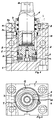
- the block cylinder consists of a housing 1 in which one cylindrical bore 2 and a threaded bore 3 are introduced.
- the threaded hole 3 is divided into those with an internal thread provided upper part 3a and into one towards the cylinder bore 2 tapered part 3b.
- the piston 5 is in the cylindrical bore 2 guided.
- the piston 5 is assigned a piston rod 6, the Cross section that corresponds to a polygon.
- the polygon is here shown triangular, it can also be in the form of a polygon square or polygon pentagon.
- the shape of the piston rod 6 corresponds to the shape of a regular polygon with all sides and angles are congruent.
- the polygonal piston rod 6 is in a guide bush 7 guided.
- the guide bush 7 is thus the inside of the polygon adapted and has seals 8 in the form of wipers that the Piston rod 6 against the inner wall of the guide bush seal.
- seals 8 There are grooves in the inner wall of the guide bush introduced that correspond to the polygon cross section and into which Seals can be inserted.
- the seals 8 have the same here Polygon shape like piston rod and guide bush.
- a additional external sealing 9 also secures the whole thing to the outside from.
- the guide bush 7 is provided with an external thread 10, so that this can be screwed into the threaded part 3a of the threaded bore 3.
- the guide bush 7 is screwed in under great prestress, which provides additional security against rotation.
- the guide bush 7 is 11 in its lower part also tapered to fit in the housing 1.
- the piston rod 6 is conical at its protruding end 12 better tool pick-up. This allows torsional moments transferred better and the tools can be in their angular position can be adjusted more easily.
- the cone version 12 is only one the possibilities for tool holder. Any other kind of Tool holder can be attached here, such as thread fastening, Holes with cross pins etc.
Landscapes
- Engineering & Computer Science (AREA)
- Physics & Mathematics (AREA)
- Fluid Mechanics (AREA)
- Mechanical Engineering (AREA)
- General Engineering & Computer Science (AREA)
- Actuator (AREA)
Abstract
Description
Claims (8)
- Blockzylinder zur Aufnahme und Führung von Werkzeugen auf Werkzeugmaschinen und Arbeitstischen, in dessen zylindrischen Bohrungen der Arbeitskolben mit Kolbenstange gleitend geführt sind und die Kolbenstange drehsicher gelagert ist, dadurch gekennzeichnet, daß die Kolbenstange (6) in einer Führungsbuchse (7) gleitend gelagert ist und daß die Kolbenstange (6) einen Querschnitt aufweist, der dem eines regelmässigen Polygons entspricht und daß die Führungsbuchse (7) mit einer zentral, axial verlaufenden Ausnehmung versehen ist, deren Querschnitt dem des Polygons der Kolbenstange (6) angepaßt ist.
- Blockzylinder nach Anspruch 1, dadurch gekennzeichnet, daß die Führungsbuchse (7) einen kreisförmigen Aussendurchmesser aufweist dessen oberer Teil (3a) mit einem Aussengewinde versehen ist.
- Blockzylinder nach Anspruch 1 u. 2, dadurch gekennzeichnet, daß das Gehäuse (1) oberhalb der Bohrung (2) des Kolbenzylinders eine abgestufte zylindrische Bohrung (3) mit größerem Durchmesser aufweist und daß in den oberen erweiterten Teil (3a) ein dem Aussengewinde der Führungsbuchse (7) angepaßtes Innengewinde eingebracht ist.
- Blockzylinder nach Anspruch 2 u. 3, dadurch gekennzeichnet, daß die in das Gehäuse (1) eingeschraubte Führungsbuchse (7) mit Aussparungen (13) versehen ist, in die eine Klemmvorrichtung (4) zur Festsetzung eingreift.
- Blockzylinder nach Anspruch 1 bis 4, dadurch gekennzeichnet, daß in die Führungsbuchse (7) im Bereich der Kolbenstangendurchführung umlaufende Nuten eingebracht sind, in die Dichtungen (8) einbringbar sind und daß die Dichtungen und Nuten dem Polygon-Querschnitt angepaßt sind.
- Blockzylinder nach Anspruch 1 bis 5, dadurch gekennzeichnet, daß die Führungsbuchse (7) an ihrem oberen Austritt der Kolbenstange eine umlaufende dem Polygon angepaßte Aussparung aufweist, in die eine Aussenabdichtung (9) eingebracht ist.
- Blockzylinder nach Anspruch 1, dadurch gekennzeichnet, daß die Kolbenstange (6) an ihrem freien aus dem Gehäuse austretenden Ende mit einem Konus (12) versehen ist.
- Blockzylinder nach Anspruch 1, dadurch gekennzeichnet, daß zur Erfassung der Kolbenstellung in den Kolben (5) Magnetsensoren (14) eingelassen sind, die in Abhängigkeit der Hubbewegung des Kolbens (5) ein der jeweiligen Kolbenstellung entsprechendes Signal abgeben.
Applications Claiming Priority (2)
| Application Number | Priority Date | Filing Date | Title |
|---|---|---|---|
| DE1997152671 DE19752671B4 (de) | 1997-11-28 | 1997-11-28 | Blockzylinder zur Aufnahme und Führung von Werkzeugen auf einer Werkzeugmaschine oder auf einem Arbeitstisch |
| DE19752671 | 1997-11-28 |
Publications (2)
| Publication Number | Publication Date |
|---|---|
| EP0919729A2 true EP0919729A2 (de) | 1999-06-02 |
| EP0919729A3 EP0919729A3 (de) | 2002-01-16 |
Family
ID=7850027
Family Applications (1)
| Application Number | Title | Priority Date | Filing Date |
|---|---|---|---|
| EP98117095A Withdrawn EP0919729A3 (de) | 1997-11-28 | 1998-09-10 | Blockzylinder mit drehsicher geführter Kolbenstange |
Country Status (2)
| Country | Link |
|---|---|
| EP (1) | EP0919729A3 (de) |
| DE (1) | DE19752671B4 (de) |
Cited By (4)
| Publication number | Priority date | Publication date | Assignee | Title |
|---|---|---|---|---|
| CN104613044A (zh) * | 2015-01-28 | 2015-05-13 | 张汉桥 | 一种液压缸组件 |
| US9281775B2 (en) | 2011-09-19 | 2016-03-08 | Ludwig Ehrhardt Gmbh | Clamping device with an electric motor |
| CN114215817A (zh) * | 2021-12-17 | 2022-03-22 | 建湖县八达液压机械有限公司 | 一种液压油缸保护装置及具有该装置的液压油缸 |
| WO2025199563A1 (de) * | 2024-03-29 | 2025-10-02 | Trumpf Maschinen Austria Gmbh & Co. Kg. | Zylinder-kolben-einheit |
Families Citing this family (2)
| Publication number | Priority date | Publication date | Assignee | Title |
|---|---|---|---|---|
| DE102016010657B4 (de) | 2016-09-02 | 2024-12-24 | Ludwig Ehrhardt Gmbh | Spannvorrichtung mit einer Sensoranordnung |
| CN109058218B (zh) * | 2018-08-28 | 2020-02-14 | 佛山市云峰精密机械有限公司 | 一种伺服刀塔用的缓冲活塞缸及伺服刀塔 |
Family Cites Families (12)
| Publication number | Priority date | Publication date | Assignee | Title |
|---|---|---|---|---|
| DE7232039U (de) * | 1973-01-04 | Klopfer A Gmbh | Werkzeughaltevorrichtung | |
| DE1934382U (de) * | 1965-12-13 | 1966-03-10 | Festo Maschf Stoll G | Kolbenstange mit fuehrung fuer einen in einem pneumatischen oder hydraulischen druckmittel gefuellten arbeitszylinder hin und her gehenden kolben. |
| US3603213A (en) * | 1969-03-12 | 1971-09-07 | Pneumo Dynamics Corp | Bushing-restrictor |
| DE2225009A1 (de) * | 1971-08-11 | 1973-02-15 | Federal Screw Works | Halter fuer ein hinterstechwerkzeug fuer automatischeschraubenbaenke oder dgl |
| DE2519251A1 (de) * | 1975-04-30 | 1976-11-11 | Reinhold Pilzecker | Arbeitsgeraet, bestehend aus kolbenstange und zylinder |
| JPS58217805A (ja) * | 1982-06-11 | 1983-12-17 | Kootaki Kk | 圧力シリンダ装置及びそれを用いた油圧プレス装置 |
| DE3427124A1 (de) * | 1983-07-23 | 1985-01-31 | Hermann Dipl.-Ing. 7140 Ludwigsburg Kastner | Teilbares werkzeug fuer die spanabhebende bearbeitung |
| DE3435964A1 (de) * | 1984-09-29 | 1986-04-10 | Teja 7814 Breisach Winterhalter | Zylinder mit verdrehungsgesicherter kolbenstange |
| JPS63122902A (ja) * | 1986-11-13 | 1988-05-26 | Ckd Controls Ltd | 移動体の位置確認装置 |
| EP0611623B1 (de) * | 1993-02-19 | 1996-04-17 | Alfred H. Schütte GmbH & Co. KG. | Aufspannvorrichtung |
| DE19500137A1 (de) * | 1995-01-04 | 1996-07-11 | Beetz Hydraulik Gmbh | Druckmittelbetätigte Zylinder-Kolben-Anordnung mit einem Magnetfeldsensor |
| DE19530131C1 (de) * | 1995-08-16 | 1996-09-05 | Spinner Werkzeugmaschinenfabri | Fluidisch betätigbare Spannvorrichtung |
-
1997
- 1997-11-28 DE DE1997152671 patent/DE19752671B4/de not_active Expired - Lifetime
-
1998
- 1998-09-10 EP EP98117095A patent/EP0919729A3/de not_active Withdrawn
Cited By (6)
| Publication number | Priority date | Publication date | Assignee | Title |
|---|---|---|---|---|
| US9281775B2 (en) | 2011-09-19 | 2016-03-08 | Ludwig Ehrhardt Gmbh | Clamping device with an electric motor |
| CN104613044A (zh) * | 2015-01-28 | 2015-05-13 | 张汉桥 | 一种液压缸组件 |
| CN114215817A (zh) * | 2021-12-17 | 2022-03-22 | 建湖县八达液压机械有限公司 | 一种液压油缸保护装置及具有该装置的液压油缸 |
| CN114215817B (zh) * | 2021-12-17 | 2024-03-01 | 建湖县八达液压机械有限公司 | 一种具有保护装置的液压油缸 |
| WO2025199563A1 (de) * | 2024-03-29 | 2025-10-02 | Trumpf Maschinen Austria Gmbh & Co. Kg. | Zylinder-kolben-einheit |
| AT528353A1 (de) * | 2024-03-29 | 2025-10-15 | Trumpf Maschinen Austria Gmbh & Co Kg | Zylinder-Kolben-Einheit |
Also Published As
| Publication number | Publication date |
|---|---|
| EP0919729A3 (de) | 2002-01-16 |
| DE19752671B4 (de) | 2006-11-23 |
| DE19752671A1 (de) | 1999-06-02 |
Similar Documents
| Publication | Publication Date | Title |
|---|---|---|
| DE60204741T2 (de) | Anordnung von Pneumatikmodulen | |
| EP2708327B1 (de) | Spannvorrichtung zum Dehnen eines Gewindebolzens sowie hierfür geeignetes Werkzeug, vorzugsweise Antriebsadapter | |
| EP4349532A2 (de) | Gerätekopf eines hydraulisch betätigbaren werkzeugs | |
| EP0715083B1 (de) | Kolbenstangenloser Druckmittelzylinder | |
| DE102010048068B4 (de) | Ventilanordnung | |
| DE3544130A1 (de) | Greifer fuer handhabungsgeraete | |
| EP0252208B2 (de) | Fluidbetätigter Zylinder | |
| EP1312810B1 (de) | Kolben/Zylinder-Einheit mit einer Drehsicherung zwichen Kolben und Kolbenstange | |
| EP0919729A2 (de) | Blockzylinder mit drehsicher geführter Kolbenstange | |
| DE102008006045A1 (de) | Tablettenpresse | |
| EP1050685B1 (de) | Hydraulischer Linearwegschieber | |
| DE1079930B (de) | Hydraulische Druckausgleichvorrichtung fuer Arbeitsmaschinen | |
| DE3025156A1 (de) | Presse mit einem stanz- und/oder presswerkzeug | |
| DE2522560C3 (de) | Druckmittelbetriebener Stellantrieb mit einem in einem geraden Zylinder hin und her verschiebbaren Arbeitskolben | |
| DE4210512C2 (de) | Druckmittelbetätigter Kraftschrauber | |
| DE3140837A1 (de) | Druckgiessmaschine | |
| DE3734987C1 (de) | Schneidrotor mit auswechselbaren Messerleisten zum Zerkleinern von festen Materialien | |
| EP0046977B1 (de) | Auf einem Gatterrahmen anbringbare hydraulische Spanneinrichtung zum Spannen von Sägeblättern | |
| DE4312275C2 (de) | Rollenwechsler mit einem Arbeitszylinder | |
| DE2402769A1 (de) | Doppeltwirkender hydraulikzylinder zur zylinderab- und -anstellung fuer druckmaschinen | |
| DE10203791B4 (de) | Fluidische Arbeitseinheit mit integrierter Ansteuerelektronik | |
| DE2156633C3 (de) | Kolben-Zylinder-Anordnung mit einem mehrteiligen Kolben | |
| DE10352548A1 (de) | Spannvorrichtung | |
| DE1502886C (de) | Spannfutter | |
| DE1267944B (de) | Hydraulisches Spannelement, insbesondere zum Spannen von Fraesern auf einem Fraesdorn |
Legal Events
| Date | Code | Title | Description |
|---|---|---|---|
| PUAI | Public reference made under article 153(3) epc to a published international application that has entered the european phase |
Free format text: ORIGINAL CODE: 0009012 |
|
| AK | Designated contracting states |
Kind code of ref document: A2 Designated state(s): AT BE CH CY DE DK ES FI FR GB GR IE IT LI LU MC NL PT SE Kind code of ref document: A2 Designated state(s): DE FR GB IT |
|
| AX | Request for extension of the european patent |
Free format text: AL;LT;LV;MK;RO;SI |
|
| PUAL | Search report despatched |
Free format text: ORIGINAL CODE: 0009013 |
|
| AK | Designated contracting states |
Kind code of ref document: A3 Designated state(s): AT BE CH CY DE DK ES FI FR GB GR IE IT LI LU MC NL PT SE |
|
| AX | Request for extension of the european patent |
Free format text: AL;LT;LV;MK;RO;SI |
|
| 17P | Request for examination filed |
Effective date: 20020710 |
|
| AKX | Designation fees paid |
Free format text: DE FR GB IT |
|
| 17Q | First examination report despatched |
Effective date: 20030313 |
|
| STAA | Information on the status of an ep patent application or granted ep patent |
Free format text: STATUS: THE APPLICATION IS DEEMED TO BE WITHDRAWN |
|
| 18D | Application deemed to be withdrawn |
Effective date: 20030724 |