EP0919762A1 - Verfahren zum Auskleiden eines Rohres oder einer Leitung - Google Patents
Verfahren zum Auskleiden eines Rohres oder einer Leitung Download PDFInfo
- Publication number
- EP0919762A1 EP0919762A1 EP98308234A EP98308234A EP0919762A1 EP 0919762 A1 EP0919762 A1 EP 0919762A1 EP 98308234 A EP98308234 A EP 98308234A EP 98308234 A EP98308234 A EP 98308234A EP 0919762 A1 EP0919762 A1 EP 0919762A1
- Authority
- EP
- European Patent Office
- Prior art keywords
- liner
- tubular support
- host pipe
- conduit
- adhesive
- Prior art date
- Legal status (The legal status is an assumption and is not a legal conclusion. Google has not performed a legal analysis and makes no representation as to the accuracy of the status listed.)
- Granted
Links
- 238000000034 method Methods 0.000 title claims abstract description 44
- 239000000853 adhesive Substances 0.000 claims abstract description 40
- 230000001070 adhesive effect Effects 0.000 claims abstract description 40
- 238000001125 extrusion Methods 0.000 claims description 13
- 239000011248 coating agent Substances 0.000 claims description 12
- 238000000576 coating method Methods 0.000 claims description 12
- 239000012530 fluid Substances 0.000 claims description 9
- 239000002390 adhesive tape Substances 0.000 claims description 6
- 229920000098 polyolefin Polymers 0.000 claims description 4
- 239000000463 material Substances 0.000 claims description 3
- 239000002131 composite material Substances 0.000 claims description 2
- 230000006835 compression Effects 0.000 description 5
- 238000007906 compression Methods 0.000 description 5
- 229920001903 high density polyethylene Polymers 0.000 description 3
- 239000004700 high-density polyethylene Substances 0.000 description 3
- 230000008569 process Effects 0.000 description 3
- 230000004075 alteration Effects 0.000 description 2
- 230000008901 benefit Effects 0.000 description 2
- 238000007796 conventional method Methods 0.000 description 2
- 239000000203 mixture Substances 0.000 description 2
- 238000012986 modification Methods 0.000 description 2
- 230000004048 modification Effects 0.000 description 2
- 239000004033 plastic Substances 0.000 description 2
- 229920003023 plastic Polymers 0.000 description 2
- -1 polyethylene Polymers 0.000 description 2
- 229920000642 polymer Polymers 0.000 description 2
- 230000003014 reinforcing effect Effects 0.000 description 2
- XLYOFNOQVPJJNP-UHFFFAOYSA-N water Substances O XLYOFNOQVPJJNP-UHFFFAOYSA-N 0.000 description 2
- OKTJSMMVPCPJKN-UHFFFAOYSA-N Carbon Chemical compound [C] OKTJSMMVPCPJKN-UHFFFAOYSA-N 0.000 description 1
- 239000004952 Polyamide Substances 0.000 description 1
- 239000004698 Polyethylene Substances 0.000 description 1
- 239000004743 Polypropylene Substances 0.000 description 1
- 230000004888 barrier function Effects 0.000 description 1
- 229910052799 carbon Inorganic materials 0.000 description 1
- 229920001577 copolymer Polymers 0.000 description 1
- 238000006073 displacement reaction Methods 0.000 description 1
- 239000007789 gas Substances 0.000 description 1
- 238000010438 heat treatment Methods 0.000 description 1
- 229920001519 homopolymer Polymers 0.000 description 1
- 238000003780 insertion Methods 0.000 description 1
- 230000037431 insertion Effects 0.000 description 1
- 238000009434 installation Methods 0.000 description 1
- 238000011900 installation process Methods 0.000 description 1
- 229920002647 polyamide Polymers 0.000 description 1
- 229920000573 polyethylene Polymers 0.000 description 1
- 229920001155 polypropylene Polymers 0.000 description 1
- 239000012779 reinforcing material Substances 0.000 description 1
Images



Classifications
-
- F—MECHANICAL ENGINEERING; LIGHTING; HEATING; WEAPONS; BLASTING
- F16—ENGINEERING ELEMENTS AND UNITS; GENERAL MEASURES FOR PRODUCING AND MAINTAINING EFFECTIVE FUNCTIONING OF MACHINES OR INSTALLATIONS; THERMAL INSULATION IN GENERAL
- F16L—PIPES; JOINTS OR FITTINGS FOR PIPES; SUPPORTS FOR PIPES, CABLES OR PROTECTIVE TUBING; MEANS FOR THERMAL INSULATION IN GENERAL
- F16L55/00—Devices or appurtenances for use in, or in connection with, pipes or pipe systems
- F16L55/16—Devices for covering leaks in pipes or hoses, e.g. hose-menders
- F16L55/162—Devices for covering leaks in pipes or hoses, e.g. hose-menders from inside the pipe
- F16L55/165—Devices for covering leaks in pipes or hoses, e.g. hose-menders from inside the pipe a pipe or flexible liner being inserted in the damaged section
- F16L55/1651—Devices for covering leaks in pipes or hoses, e.g. hose-menders from inside the pipe a pipe or flexible liner being inserted in the damaged section the flexible liner being everted
Definitions
- This invention relates to a method of lining a host pipe or conduit by an eversion method.
- Eversion methods of lining pipelines or conduits are well known and examples of such methods can be found in, for example, EP-A-0611914, GB-A-1025011, GB-A-2082285, GB-A-1559323, EP-A-0304914, GB-A-2042673, DE-A-2718877, EP-A-062100, EP-A-0620102, JP 60-7124, JP 64-182709 and JP 64-182710.
- the invention provides a method of lining a host pipe or conduit by eversion of a liner within the host pipe or conduit; wherein the liner is of a generally flattened or axially folded configuration and is carried on a tubular support, the liner surrounding the tubular support, and the tubular support being releasably bonded to the liner by a peelable adhesive at one or more circumferential locations on the inner surface of the liner and not being bonded to the liner either side of each said location, the liner being arranged to peel away from the tubular support and evert towards or into contact with the wall of the host pipe or conduit as the tubular support is towed through the host pipe or conduit.
- tubular support is moved through the host pipe or conduit solely by mechanical means, most preferably solely by towing, and without the use of fluid pressure from behind the everting liner, and without the application of vacuum in front of the everting liner.
- the liner can be selected such that after eversion, it is in tight contact with the wall of the host pipe or conduit, or it can be undersized with respect to the host pipe such that there is initially an annular gap between the host pipe wall and the liner.
- the undersized liner can then be caused or allowed to expand to tightness against the pipe wall.
- the expansion of the liner can be achieved by means of any of a number of well known processes, which can involve for example simple stretching and plastic deformation of the liner, or by building expansive stresses into the liner and releasing the expansive stresses through heat treatment of the liner after installation.
- the liner is adhered to the tubular support prior to eversion by means of a peelable adhesive.
- a peelable adhesive is that after the liner has everted, adhesive initially on the bore of the liner is presented on the outer surface of the liner and therefore serves at least partially to bond the liner to the wall of the host pipe when the liner is brought into contact with the wall.
- adhesive on the tubular support may be transferred to parts of the liner bore ultimately to help bond the liner to the host bore in like manner.
- the peelable adhesive is typically chosen such that the aforementioned bond to the wall of the host pipe is sufficiently strong to hold the liner against any residual contractive stresses. Such contractive stresses can arise after expansion of an initially undersized liner to tightness within the host pipe as part of the installation process, or after first recommissioning of the pipeline.
- the invention provides a method of lining a host pipe or conduit by eversion of a liner within the host pipe or conduit; wherein the liner is of a generally flattened or folded configuration and is carried on a tubular support, the liner being arranged to peel away from the tubular support and evert towards or into contact with the wall of the host pipe or conduit as the tubular support is towed through the host pipe or conduit, and wherein an adhesive-dispensing head is towed along the host pipe or conduit in front of the liner, the adhesive-dispensing head being arranged to apply adhesive to the front of the everting liner and/or to the host pipe wall, prior to the liner contacting the said wall.
- the adhesive-dispensing head can be used whether or not the tubular support has been releasably bonded to the liner by means of a peelable adhesive.
- the tubular support typically is initially disposed within the liner so as to give an initial loose fit with an annular gap therebetween.
- the tubular support and liner can be formed separately and the support pulled through the bore of the liner. More usually however, the liner is extruded around the tubular support. This can be accomplished, for example, by extruding the tubular support at a first extrusion location and then extruding the liner around the tubular support at a second extrusion location downstream of the first.
- Adhesive can be applied to the inner surface of the liner and/or the outer surface of the tubular support between the first and second extrusion locations, or at one or both locations.
- the liner and tubular support are usually subjected to compression so as generally to flatten them, the flattening process serving to bond the liner to the tubular support.
- the ratio of the initial diameter (i.e. prior to compression) of the liner to the initial diameter of the tubular support is typically in the range from 2:1 to 5:1, more usually in the range 3:1 to 4:1.
- the width of the flattened liner/tubular support combination typically is greater than the diameter of the host pipe into which the liner is to be installed (although it need not be), although the depth of the combination is significantly less than the diameter of the host pipe.
- the tubular support can be towed through the host pipe or conduit by means of a cable attached to a suitable mounting point at the leading end of the support.
- An adhesive-dispensing head e.g. a dispensing lance
- a dispensing lance can be mounted so as to be movable along the host pipe in front (and preferably immediately in front) of the everting liner.
- the lance can be mounted on a second cable, the dispensing head being connected to a supply line containing adhesive.
- the supply line can extend through the bore of the tubular support but more usually extends into the host pipe from the remote end thereof, i.e. the end at which the towing cable is connected to a winch or other towing means.
- the tubular support is usually formed from a plastics material such as a polyolefin e.g. polyethylene (high strength HDPE) or polypropylene.
- a polyolefin e.g. polyethylene (high strength HDPE) or polypropylene.
- the liner is typically formed from a polymer such as a polyolefin homopolymer or a copolymer or mixture thereof.
- the liner can be unilaminar or have more than one layer.
- the liner can have a main structural layer and a barrier layer formed from a polymer such as a polyamide.
- a reinforcing layer can also be present, for example a reinforcing layer containing a fibrous reinforcing material such as carbon fibres.
- the method of the present invention can be used for example to introduce into the bore of a host pipe or conduit liners having a wall thickness in the range from 0.1mm to 15mm, e.g. 0.5mm to 5mm.
- the invention provides a method of forming a supported liner suitable for use in the method as hereinbefore defined, the method comprising applying a peelable adhesive to the outer surface of a tubular support (e.g. by coating) and/or applying a peelable adhesive to the inner surface of the liner (e.g by coating), positioning the tubular support within the bore of a liner, and compressing the liner and tubular support so that the liner is urged into contact with the tubular support and is peelably bonded thereto over part, but not all, of its circumference.
- the method comprises extruding the tubular support at a first extrusion location; extruding the liner about the tubular support at a second extrusion location downstream of the first, such that the tubular support is initially loosely disposed within the liner; applying (e.g. by coating) a peelable adhesive to the outer surface of the tubular support and/or the inner surface of the liner; and then compressing the liner and tubular support to form a generally flattened composite assembly in which the liner is peelably bonded to the tubular support over part, but not all, of its circumference.
- the peelable adhesive can be, for example, applied as a coating to the outer surface of the tubular support; or it can be applied as a coating to the inner surface of the liner.
- the peelable adhesive can be applied in the form of one or more adhesive tapes, for example extending generally axially along the outer surface of the tubular support.
- the adhesive tape(s) can be double sided, the two sides of the tape having adhesives thereon of different peel strength, one side having a relatively high peel strength adhesive being bonded to the liner and the other side having a relatively low peel strength adhesive being bonded to the tubular support.
- the invention provides a liner supported on a tubular support as hereinbefore defined.
- Figure 1 illustrates a known method of eversion lining of a pipe or conduit as described in European Patent Application EP-A-0 301 895.
- a host pipe 2 is lined with a flexible liner 4 which is fed into the bore of the host pipe from a reel 6.
- One end 4a of the liner is secured about the mouth 2a of the host pipe , and the liner is then forced into the host pipe by the pressure of a compressed fluid (indicated schematically by the letter P) such as compressed air or water.
- a compressed fluid indicated schematically by the letter P
- the liner 4 can instead be drawn through the host pipe by the application of vacuum to the leading surface of the liner.
- a major disadvantage of the arrangement shown in Figure 1 is that it requires the use of a source of fluid pressure or vacuum, which in turn requires the components of the lining system to be fitted together in a fluid tight condition.
- a further disadvantage is that for relatively small bore pipes, very large pressures tend to be required in order to bring about eversion.
- the present invention provides a means of avoiding the use of fluid pressure, the liner being capable of being everted simply by towing it through the host pipe using a suitable winch or other towing device.
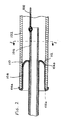
- a host pipe 102 is lined with a liner 104 which can be formed from, for example, a polyolefin mixture of 2mm thickness.
- the liner 104 is carried on a tubular support 106, which can be formed from a high density polyethylene (HDPE).
- a towing cable 108 To the leading end of the tubular support 106 is attached an end of a towing cable 108, the other end of which is attached to a winch at the remote end of the host pipe.
- the tubular support and liner are initially both formed in a circular cross section, the tubular support being extruded through a suitable die of a conventional extruder at a first extrusion location and the liner being extruded around the tubular support at a second extrusion location downstream of the first. Between the first and second extrusion locations, or at one of the locations, a layer 110 of a tacky peelable adhesive is coated onto the outer surface of the tubular support and/or the inner surface of the liner. As shown in Figure 5, immediately after extrusion of the liner around the tubular support, the tubular support is loosely arranged within the liner.
- the tubular support/liner combination shown in Figure 5 is compressed, for example between rollers, to give a profile as shown in Figure 6.
- the liner is bonded to the tubular support by the peelable adhesive. Once the compressive force is released, the resilience of the material causes it to resile to a limited extent towards a more circular "eye" shape as shown in Figure 7, before the combination is wound on to a drum as shown in Figure 8.
- an end 104a of the liner 104 is stretched over the mouth 102a of the host pipe by means of a suitable expanding tool optionally provided with thermal softening capability, and the cable 108 is used to draw the tubular support and liner into the bore of the host pipe 102.
- a suitable expanding tool optionally provided with thermal softening capability
- the cable 108 is used to draw the tubular support and liner into the bore of the host pipe 102.
- the flattened form of the liner/support combination means that the width W of the liner is typically greater than the diameter of the host pipe.
- the liner 104 is progressively peeled away from the support and turned inside out (everted) such that the surface 104b formerly facing radially inwardly, now faces radially outwardly and is in contact with or near to the wall 112 of the host pipe.
- part of the surface of the liner will have been in contact with the tubular support and will therefore have picked up a layer of peelable adhesive from the support.
- substantially all of the surface of the liner can be provided with a coating of peelable adhesive, the adhesive having been applied to the inner surface of the liner during the extrusion step. Following eversion, the peelable adhesive on the liner helps to secure the liner in place against the host pipe and prevent inadvertent axial displacement along the host pipe.
- a major advantage of the method of the invention is that it avoids the need for the complex equipment and fluid-tight conditions typically required for everting liners using fluid pressure or vacuum. Instead, the liner can be introduced into the host pipe simply by towing the tubular support through the host pipe with a conventional winch.
Landscapes
- Engineering & Computer Science (AREA)
- General Engineering & Computer Science (AREA)
- Mechanical Engineering (AREA)
- Lining Or Joining Of Plastics Or The Like (AREA)
- Application Of Or Painting With Fluid Materials (AREA)
- Protection Of Pipes Against Damage, Friction, And Corrosion (AREA)
Applications Claiming Priority (2)
| Application Number | Priority Date | Filing Date | Title |
|---|---|---|---|
| GB9724939 | 1997-11-26 | ||
| GB9724939A GB2331793A (en) | 1997-11-26 | 1997-11-26 | A method of lining a host pipe or conduit |
Publications (2)
| Publication Number | Publication Date |
|---|---|
| EP0919762A1 true EP0919762A1 (de) | 1999-06-02 |
| EP0919762B1 EP0919762B1 (de) | 2003-04-16 |
Family
ID=10822639
Family Applications (1)
| Application Number | Title | Priority Date | Filing Date |
|---|---|---|---|
| EP98308234A Expired - Lifetime EP0919762B1 (de) | 1997-11-26 | 1998-10-09 | Verfahren zum Auskleiden eines Rohres oder einer Leitung und eine Auskleidung |
Country Status (4)
| Country | Link |
|---|---|
| EP (1) | EP0919762B1 (de) |
| AT (1) | ATE237781T1 (de) |
| DE (1) | DE69813466D1 (de) |
| GB (1) | GB2331793A (de) |
Cited By (4)
| Publication number | Priority date | Publication date | Assignee | Title |
|---|---|---|---|---|
| WO2009053343A3 (en) * | 2007-10-23 | 2010-05-14 | Shell Internationale Research Maatschappij B.V. | Method of radially expanding a tubular element in a wellbore provided with a control line |
| WO2009074643A3 (en) * | 2007-12-13 | 2010-08-19 | Shell Internationale Research Maatschappij B.V. | Method of creating a wellbore system |
| WO2009087068A3 (en) * | 2008-01-04 | 2010-09-16 | Shell Internationale Research Maatschappij B.V. | Method of expanding a tubular element in a wellbore |
| US7922855B2 (en) | 2002-06-18 | 2011-04-12 | Sideliner Enterprises Pty Ltd. | Method for guiding everting form employed to carry repair material into pipe or conduit |
Families Citing this family (1)
| Publication number | Priority date | Publication date | Assignee | Title |
|---|---|---|---|---|
| NZ538556A (en) * | 2002-09-02 | 2007-12-21 | Shieldliner Ltd | Method for high-frequency tuning an electrical device and a printed circuit board suitable therefor |
Citations (6)
| Publication number | Priority date | Publication date | Assignee | Title |
|---|---|---|---|---|
| US4077610A (en) * | 1976-01-06 | 1978-03-07 | Senichi Masuda | Method and apparatus for passing an article through an interior of a pipe |
| DE3513956A1 (de) * | 1985-04-18 | 1986-10-30 | Müller, Hans, 4938 Schieder-Schwalenberg | Verfahren zum sanieren einer im erdreich verlegten rohrleitung |
| WO1990009541A1 (en) * | 1989-02-10 | 1990-08-23 | Insituform Group Limited | Improvements relating to the lining of pipelines and passageways |
| US5388616A (en) * | 1993-05-19 | 1995-02-14 | Mueller; Hans | Invertible liner for internal surfaces of fluid conveying pipes and the like |
| WO1995020125A1 (en) * | 1994-01-21 | 1995-07-27 | Insituform Technologies Ltd. | Improvements relating to the lining of pipelines or passageways |
| GB2302384A (en) * | 1995-06-17 | 1997-01-15 | Applied Felts Limited | Forming and impregnating a liner and lining a pipe |
Family Cites Families (2)
| Publication number | Priority date | Publication date | Assignee | Title |
|---|---|---|---|---|
| US4334943A (en) * | 1979-07-30 | 1982-06-15 | Tokyo Gas Kabushiki Kaisha | Method for smoothly evaginating a tubular material under pressure |
| FR2701751B1 (fr) * | 1993-02-19 | 1995-05-19 | Lionel Richard | Tube flexible qui se dispose dans une galerie en s'appliquant progressivement sur tout le diamètre intérieur de celle-ci. |
-
1997
- 1997-11-26 GB GB9724939A patent/GB2331793A/en not_active Withdrawn
-
1998
- 1998-10-09 DE DE69813466T patent/DE69813466D1/de not_active Expired - Lifetime
- 1998-10-09 EP EP98308234A patent/EP0919762B1/de not_active Expired - Lifetime
- 1998-10-09 AT AT98308234T patent/ATE237781T1/de not_active IP Right Cessation
Patent Citations (6)
| Publication number | Priority date | Publication date | Assignee | Title |
|---|---|---|---|---|
| US4077610A (en) * | 1976-01-06 | 1978-03-07 | Senichi Masuda | Method and apparatus for passing an article through an interior of a pipe |
| DE3513956A1 (de) * | 1985-04-18 | 1986-10-30 | Müller, Hans, 4938 Schieder-Schwalenberg | Verfahren zum sanieren einer im erdreich verlegten rohrleitung |
| WO1990009541A1 (en) * | 1989-02-10 | 1990-08-23 | Insituform Group Limited | Improvements relating to the lining of pipelines and passageways |
| US5388616A (en) * | 1993-05-19 | 1995-02-14 | Mueller; Hans | Invertible liner for internal surfaces of fluid conveying pipes and the like |
| WO1995020125A1 (en) * | 1994-01-21 | 1995-07-27 | Insituform Technologies Ltd. | Improvements relating to the lining of pipelines or passageways |
| GB2302384A (en) * | 1995-06-17 | 1997-01-15 | Applied Felts Limited | Forming and impregnating a liner and lining a pipe |
Cited By (7)
| Publication number | Priority date | Publication date | Assignee | Title |
|---|---|---|---|---|
| US7922855B2 (en) | 2002-06-18 | 2011-04-12 | Sideliner Enterprises Pty Ltd. | Method for guiding everting form employed to carry repair material into pipe or conduit |
| WO2009053343A3 (en) * | 2007-10-23 | 2010-05-14 | Shell Internationale Research Maatschappij B.V. | Method of radially expanding a tubular element in a wellbore provided with a control line |
| US8056641B2 (en) | 2007-10-23 | 2011-11-15 | Shell Oil Company | Method of radially expanding a tubular element in a wellbore provided with a control line |
| WO2009074643A3 (en) * | 2007-12-13 | 2010-08-19 | Shell Internationale Research Maatschappij B.V. | Method of creating a wellbore system |
| US8555987B2 (en) | 2007-12-13 | 2013-10-15 | Shell Oil Company | Method of creating a wellbore system |
| WO2009087068A3 (en) * | 2008-01-04 | 2010-09-16 | Shell Internationale Research Maatschappij B.V. | Method of expanding a tubular element in a wellbore |
| US8430177B2 (en) | 2008-01-04 | 2013-04-30 | Shell Oil Company | Method of expanding a tubular element in a wellbore |
Also Published As
| Publication number | Publication date |
|---|---|
| ATE237781T1 (de) | 2003-05-15 |
| GB2331793A (en) | 1999-06-02 |
| GB9724939D0 (en) | 1998-01-28 |
| DE69813466D1 (de) | 2003-05-22 |
| EP0919762B1 (de) | 2003-04-16 |
Similar Documents
| Publication | Publication Date | Title |
|---|---|---|
| US6612340B1 (en) | Turnback protection for installation of cured in place liners | |
| EP1034394B1 (de) | Verfahren und system zur örtlichen reparatur von rohren und rohrleitungen | |
| EP0887584B1 (de) | Vorrichtung für die Reparatur eines Rohres und ein Verfahren zur Benutzung derselben | |
| US5964249A (en) | Apparatus and method for repairing a pipeline | |
| US5680885A (en) | Method for rehabilitating pipe | |
| US20030159776A1 (en) | Apparatus for and method of lining passageways | |
| EP1685346B1 (de) | In-situ ausgehärtete auskleidung mit integraler undurchlässiger innenschicht und dauerherstellungsverfahren | |
| US6006787A (en) | Branch pipe liner bag and branch pipe lining method | |
| CA2075715C (en) | Pipeline and passageway lining materials | |
| EP1690034B1 (de) | Verfahren zum installieren einer vor ort ausgehärteten harzimprägnierten rohrinnenauskleidung | |
| US5346658A (en) | Method for installing a pipe liner | |
| JP2004168022A (ja) | 地中管のライニング | |
| EP0919762B1 (de) | Verfahren zum Auskleiden eines Rohres oder einer Leitung und eine Auskleidung | |
| US5954903A (en) | Branched sewer re-lining | |
| US7922855B2 (en) | Method for guiding everting form employed to carry repair material into pipe or conduit | |
| JP3803821B2 (ja) | 管のライニング方法 | |
| JP3113809B2 (ja) | ライニング用樹脂管のドラム巻回方法 | |
| JP2000161585A (ja) | 管内ライニング工法 | |
| EP1390658B1 (de) | Verfahren und vorrichtung zum anlegen eines getrennten kanals innerhalb einer fluidbeförderungsleitung | |
| JP3400955B2 (ja) | 既設配管の更生用パイプ及び既設配管更生修理工法 | |
| CA2096745A1 (en) | Lining of pipelines or passageways | |
| JP4860377B2 (ja) | 埋設取付管の更生方法 | |
| JPH02202431A (ja) | 管の内面ライニング工法及びライニング用管体 | |
| AU737147B2 (en) | System for the formed-in-situ localised repair of pipes and conduits | |
| AU652245B2 (en) | Method for the repair of localised damaged portions of a cement sewer pipe laid beneath the surface of the ground |
Legal Events
| Date | Code | Title | Description |
|---|---|---|---|
| PUAI | Public reference made under article 153(3) epc to a published international application that has entered the european phase |
Free format text: ORIGINAL CODE: 0009012 |
|
| AK | Designated contracting states |
Kind code of ref document: A1 Designated state(s): AT BE CH CY DE DK ES FI FR GB GR IE IT LI LU MC NL PT Kind code of ref document: A1 Designated state(s): AT BE CH DE DK ES FI FR GB GR IE IT LI LU MC NL PT SE |
|
| AX | Request for extension of the european patent |
Free format text: AL;LT;LV;MK;RO;SI |
|
| 17P | Request for examination filed |
Effective date: 19991130 |
|
| AKX | Designation fees paid |
Free format text: AT BE CH CY DE DK ES FI FR GB GR IE IT LI LU MC NL PT |
|
| RBV | Designated contracting states (corrected) |
Designated state(s): AT BE CH DE DK ES FI FR GB GR IE IT LI LU MC NL PT SE |
|
| 17Q | First examination report despatched |
Effective date: 20010928 |
|
| RTI1 | Title (correction) |
Free format text: A METHOD OF LINING A HOST PIPE OR CONDUIT AND A LINER |
|
| GRAH | Despatch of communication of intention to grant a patent |
Free format text: ORIGINAL CODE: EPIDOS IGRA |
|
| GRAH | Despatch of communication of intention to grant a patent |
Free format text: ORIGINAL CODE: EPIDOS IGRA |
|
| GRAA | (expected) grant |
Free format text: ORIGINAL CODE: 0009210 |
|
| AK | Designated contracting states |
Designated state(s): AT BE CH DE DK ES FI FR GB GR IE IT LI LU MC NL PT SE |
|
| PG25 | Lapsed in a contracting state [announced via postgrant information from national office to epo] |
Ref country code: NL Free format text: LAPSE BECAUSE OF FAILURE TO SUBMIT A TRANSLATION OF THE DESCRIPTION OR TO PAY THE FEE WITHIN THE PRESCRIBED TIME-LIMIT Effective date: 20030416 Ref country code: LI Free format text: LAPSE BECAUSE OF FAILURE TO SUBMIT A TRANSLATION OF THE DESCRIPTION OR TO PAY THE FEE WITHIN THE PRESCRIBED TIME-LIMIT Effective date: 20030416 Ref country code: IT Free format text: LAPSE BECAUSE OF FAILURE TO SUBMIT A TRANSLATION OF THE DESCRIPTION OR TO PAY THE FEE WITHIN THE PRE;WARNING: LAPSES OF ITALIAN PATENTS WITH EFFECTIVE DATE BEFORE 2007 MAY HAVE OCCURRED AT ANY TIME BEFORE 2007. THE CORRECT EFFECTIVE DATE MAY BE DIFFERENT FROM THE ONE RECORDED.SCRIBED TIME-LIMIT Effective date: 20030416 Ref country code: FR Free format text: LAPSE BECAUSE OF FAILURE TO SUBMIT A TRANSLATION OF THE DESCRIPTION OR TO PAY THE FEE WITHIN THE PRESCRIBED TIME-LIMIT Effective date: 20030416 Ref country code: FI Free format text: LAPSE BECAUSE OF FAILURE TO SUBMIT A TRANSLATION OF THE DESCRIPTION OR TO PAY THE FEE WITHIN THE PRESCRIBED TIME-LIMIT Effective date: 20030416 Ref country code: CH Free format text: LAPSE BECAUSE OF FAILURE TO SUBMIT A TRANSLATION OF THE DESCRIPTION OR TO PAY THE FEE WITHIN THE PRESCRIBED TIME-LIMIT Effective date: 20030416 Ref country code: BE Free format text: LAPSE BECAUSE OF FAILURE TO SUBMIT A TRANSLATION OF THE DESCRIPTION OR TO PAY THE FEE WITHIN THE PRESCRIBED TIME-LIMIT Effective date: 20030416 Ref country code: AT Free format text: LAPSE BECAUSE OF FAILURE TO SUBMIT A TRANSLATION OF THE DESCRIPTION OR TO PAY THE FEE WITHIN THE PRESCRIBED TIME-LIMIT Effective date: 20030416 |
|
| REG | Reference to a national code |
Ref country code: GB Ref legal event code: FG4D |
|
| REG | Reference to a national code |
Ref country code: CH Ref legal event code: EP |
|
| REF | Corresponds to: |
Ref document number: 69813466 Country of ref document: DE Date of ref document: 20030522 Kind code of ref document: P |
|
| REG | Reference to a national code |
Ref country code: IE Ref legal event code: FG4D |
|
| PG25 | Lapsed in a contracting state [announced via postgrant information from national office to epo] |
Ref country code: SE Free format text: LAPSE BECAUSE OF FAILURE TO SUBMIT A TRANSLATION OF THE DESCRIPTION OR TO PAY THE FEE WITHIN THE PRESCRIBED TIME-LIMIT Effective date: 20030716 Ref country code: PT Free format text: LAPSE BECAUSE OF FAILURE TO SUBMIT A TRANSLATION OF THE DESCRIPTION OR TO PAY THE FEE WITHIN THE PRESCRIBED TIME-LIMIT Effective date: 20030716 Ref country code: GR Free format text: LAPSE BECAUSE OF FAILURE TO SUBMIT A TRANSLATION OF THE DESCRIPTION OR TO PAY THE FEE WITHIN THE PRESCRIBED TIME-LIMIT Effective date: 20030716 Ref country code: DK Free format text: LAPSE BECAUSE OF FAILURE TO SUBMIT A TRANSLATION OF THE DESCRIPTION OR TO PAY THE FEE WITHIN THE PRESCRIBED TIME-LIMIT Effective date: 20030716 |
|
| PG25 | Lapsed in a contracting state [announced via postgrant information from national office to epo] |
Ref country code: DE Free format text: LAPSE BECAUSE OF FAILURE TO SUBMIT A TRANSLATION OF THE DESCRIPTION OR TO PAY THE FEE WITHIN THE PRESCRIBED TIME-LIMIT Effective date: 20030717 |
|
| NLV1 | Nl: lapsed or annulled due to failure to fulfill the requirements of art. 29p and 29m of the patents act | ||
| PG25 | Lapsed in a contracting state [announced via postgrant information from national office to epo] |
Ref country code: LU Free format text: LAPSE BECAUSE OF NON-PAYMENT OF DUE FEES Effective date: 20031009 |
|
| PG25 | Lapsed in a contracting state [announced via postgrant information from national office to epo] |
Ref country code: ES Free format text: LAPSE BECAUSE OF FAILURE TO SUBMIT A TRANSLATION OF THE DESCRIPTION OR TO PAY THE FEE WITHIN THE PRESCRIBED TIME-LIMIT Effective date: 20031030 |
|
| PG25 | Lapsed in a contracting state [announced via postgrant information from national office to epo] |
Ref country code: MC Free format text: LAPSE BECAUSE OF NON-PAYMENT OF DUE FEES Effective date: 20031031 |
|
| REG | Reference to a national code |
Ref country code: CH Ref legal event code: PL |
|
| PLBE | No opposition filed within time limit |
Free format text: ORIGINAL CODE: 0009261 |
|
| STAA | Information on the status of an ep patent application or granted ep patent |
Free format text: STATUS: NO OPPOSITION FILED WITHIN TIME LIMIT |
|
| 26N | No opposition filed |
Effective date: 20040119 |
|
| EN | Fr: translation not filed | ||
| PGFP | Annual fee paid to national office [announced via postgrant information from national office to epo] |
Ref country code: IE Payment date: 20100902 Year of fee payment: 13 |
|
| PGFP | Annual fee paid to national office [announced via postgrant information from national office to epo] |
Ref country code: GB Payment date: 20110908 Year of fee payment: 14 |
|
| REG | Reference to a national code |
Ref country code: IE Ref legal event code: MM4A |
|
| PG25 | Lapsed in a contracting state [announced via postgrant information from national office to epo] |
Ref country code: IE Free format text: LAPSE BECAUSE OF NON-PAYMENT OF DUE FEES Effective date: 20111009 |
|
| GBPC | Gb: european patent ceased through non-payment of renewal fee |
Effective date: 20121009 |
|
| PG25 | Lapsed in a contracting state [announced via postgrant information from national office to epo] |
Ref country code: GB Free format text: LAPSE BECAUSE OF NON-PAYMENT OF DUE FEES Effective date: 20121009 |