EP0919763A1 - Justierelement für Koordinatenmessgeräte - Google Patents
Justierelement für Koordinatenmessgeräte Download PDFInfo
- Publication number
- EP0919763A1 EP0919763A1 EP98120214A EP98120214A EP0919763A1 EP 0919763 A1 EP0919763 A1 EP 0919763A1 EP 98120214 A EP98120214 A EP 98120214A EP 98120214 A EP98120214 A EP 98120214A EP 0919763 A1 EP0919763 A1 EP 0919763A1
- Authority
- EP
- European Patent Office
- Prior art keywords
- foundation
- adjustment
- component
- anchor
- height
- Prior art date
- Legal status (The legal status is an assumption and is not a legal conclusion. Google has not performed a legal analysis and makes no representation as to the accuracy of the status listed.)
- Granted
Links
- 238000000034 method Methods 0.000 claims abstract description 11
- 239000000463 material Substances 0.000 claims description 41
- 238000004382 potting Methods 0.000 claims description 40
- 239000004568 cement Substances 0.000 claims description 4
- 238000004873 anchoring Methods 0.000 claims description 3
- 230000008961 swelling Effects 0.000 claims description 3
- 239000011440 grout Substances 0.000 abstract 2
- 238000005259 measurement Methods 0.000 abstract 2
- 238000010276 construction Methods 0.000 description 3
- 230000003287 optical effect Effects 0.000 description 2
- 239000000523 sample Substances 0.000 description 2
- XLYOFNOQVPJJNP-UHFFFAOYSA-N water Substances O XLYOFNOQVPJJNP-UHFFFAOYSA-N 0.000 description 2
- 238000005253 cladding Methods 0.000 description 1
- 238000011161 development Methods 0.000 description 1
- 230000018109 developmental process Effects 0.000 description 1
- 238000005553 drilling Methods 0.000 description 1
- 238000005516 engineering process Methods 0.000 description 1
- 239000002184 metal Substances 0.000 description 1
- 230000002522 swelling effect Effects 0.000 description 1
Images
Classifications
-
- G—PHYSICS
- G01—MEASURING; TESTING
- G01B—MEASURING LENGTH, THICKNESS OR SIMILAR LINEAR DIMENSIONS; MEASURING ANGLES; MEASURING AREAS; MEASURING IRREGULARITIES OF SURFACES OR CONTOURS
- G01B5/00—Measuring arrangements characterised by the use of mechanical techniques
- G01B5/004—Measuring arrangements characterised by the use of mechanical techniques for measuring coordinates of points
- G01B5/008—Measuring arrangements characterised by the use of mechanical techniques for measuring coordinates of points using coordinate measuring machines
-
- F—MECHANICAL ENGINEERING; LIGHTING; HEATING; WEAPONS; BLASTING
- F16—ENGINEERING ELEMENTS AND UNITS; GENERAL MEASURES FOR PRODUCING AND MAINTAINING EFFECTIVE FUNCTIONING OF MACHINES OR INSTALLATIONS; THERMAL INSULATION IN GENERAL
- F16M—FRAMES, CASINGS OR BEDS OF ENGINES, MACHINES OR APPARATUS, NOT SPECIFIC TO ENGINES, MACHINES OR APPARATUS PROVIDED FOR ELSEWHERE; STANDS; SUPPORTS
- F16M7/00—Details of attaching or adjusting engine beds, frames, or supporting-legs on foundation or base; Attaching non-moving engine parts, e.g. cylinder blocks
-
- G—PHYSICS
- G01—MEASURING; TESTING
- G01B—MEASURING LENGTH, THICKNESS OR SIMILAR LINEAR DIMENSIONS; MEASURING ANGLES; MEASURING AREAS; MEASURING IRREGULARITIES OF SURFACES OR CONTOURS
- G01B5/00—Measuring arrangements characterised by the use of mechanical techniques
- G01B5/0002—Arrangements for supporting, fixing or guiding the measuring instrument or the object to be measured
Definitions
- the invention relates to an adjusting element for mounting a Component on a foundation, including a height adjustment the adjustment of the height of the component compared to the Foundation serves as well as an anchor, which anchors the Adjustment element in the foundation is used.
- the invention relates also a coordinate measuring machine, the measuring table with a Adjusting element according to the invention was attached and a corresponding method for fastening a component a foundation with said adjustment element.
- the adjustment element concerned comprises one in the foundation inserted heavy-duty dowels and one as a support trained height adjustment between the foundation and the component to be fastened is arranged, as well as a long one Screw that from the opposite side of the component to be fastened through holes in the component and in the height adjustment the heavy-duty dowel is screwed in.
- the as an edition trained height adjustment has two over one Thread connected parts on, when twisted of the two parts against each other the total height of the edition can be changed.
- Adjustment element is in the German one Patent Application 25 04 473 shown.
- the one shown here Adjustment element has a base on which Foundation is set up, and in the rotatable one Spindle is mounted.
- the spindle has in its upper area a thread on the one provided on the machine base Thread interacts in such a way that when the spindle is rotated the machine foot is raised in relation to the lower part of the foot.
- German patent application 24 14 630 is also shown an adjusting element of the type mentioned, in which a component adjustable in height mounted on an adjusting element is.
- the adjusting element has two on top of each other stored, wedge-shaped blocks on, their location by a corresponding screw can be adjusted against each other can, so that this also changes the height.
- the adjusting element comprises components that before the actual assembly of the component to be assembled exactly must be placed on the foundation.
- Both Adjustment devices must first have holes in the correct position be drilled into the foundation and in the case of the German Publications 24 14 630 and 23 44 348, respectively Height adjustments can be set up on the foundation or in the case of German Offenlegungsschrift 25 04 473 the The lower part of the foot must be mounted on the foundation before the actual component to be assembled on the parts in question the adjustment device can be stored.
- the assembly of the relevant adjustment elements is mentioned in the three Disclosures do not pose any problem since the drilling holes measured relatively easily and accurate can be drilled.
- Adjustment elements have anchors that are in a corresponding Grouting material, such as a special cement, should be cast in, since the position of the anchor up to Hardening of the potting material must remain stable.
- the components to be fastened the adjustment elements are fully attached before assembly, and positioned the component on the foundation so that the Anchors in those specially designed to hold the anchors Recesses were placed in the foundation and then the said Notches filled with the appropriate potting material were.
- This assembly method proves to be relative easy if the components to be fastened are is simple machines with four feet, however relatively complicated very quickly, if larger Measuring tables of coordinate measuring machines must be installed at which are also adjustment elements in the inner area of the Measuring table.
- our invention is based on the object the previously known adjustment elements with an anchor of the Anchoring the adjusting element in a potting material (8) in the Foundation (10) serves and the associated methods for Assembly of the components using these adjustment elements on a Develop the foundation in such a way that the anchor of the mentioned adjustment elements securely anchored in the potting material become.
- the adjusting element is mounted accordingly, then said anchor penetrates into the potting material and now positionally stable until the potting material hardens Potting material is immersed.
- the assembly is usually done so that the Adjustment element through an opening of the component is mounted, the transverse dimensions of the anchor being so are designed so that the anchor through the opening fits through.
- the adjustment element can be attached via one on the side of the adjusting element facing away from the anchor attached plate made in one over the opening protruding area on the component via appropriate screws is attached.
- the adjusting element has an external thread, which in a corresponding internal thread in said component can be screwed in.
- the said invention is particularly good for Use large components where the adjustment element be arranged in a central area of the component must, in which the recesses made with a potting material should not be freely accessible from outside.
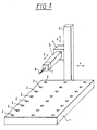
- Figure 1 shows a perspective view of a Coordinate measuring device in which a component in the form of a Measuring table (1) attached with adjusting elements according to the invention is.
- the coordinate measuring machine points here a stand (3) on the side not closer here shown on the rear face of the measuring table (1) fixed guides movable in the direction of the arrow (X) is led.
- a scale is provided by am Stand (3) attached optical measuring means is scanned.
- a cross slide (4) is in turn on the stand (3) Movable in the direction of the arrow (Z), the Cross slide (4) in turn the measuring arm (5) in the direction of Arrow (Y) moves flexibly.
- the measuring table (1) on which the The workpiece to be measured is stored here in FIG 1, not shown, adjusting elements according to the invention adjusted on the foundation, whereby said Adjustment elements are in the openings (2, 23).
- the Openings (2, 23) are only examples shown embodiment each from a bore (2) and a bore (23) into which an internal thread is cut. Of course, the openings can also be different be executed. The only important thing here is that one Connection from the top of the measuring table to the bottom of the measuring table in which the adjusting element is attached can be.
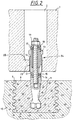
- the adjusting elements according to the invention are now closer described with reference to Figure 2, in a section Section through the measuring table (1) is shown.
- the foundation (10) on which the measuring table (1) is attached a recess in which the anchor (11) of the Adjustment element by a potting material (8) stable is poured.
- the recess was made by a so-called corrugated tube (9) generated, which before Completion of the foundation (10) in the foundation (10) was introduced.
- corrugated tubes are concerned is usually cylindrical made of sheet metal trained tubes that are closed on one side, the surface of the tube being undulating, so that the corrugated cladding tube (9) is cast well into the foundation (10) and can be attached.
- Such corrugated tubes are in the Construction industry standard elements and can for example in Construction trade.
- the armature (11) in turn is, as shown, and because of it has been running the entire length changing cross-sectional area the particularly advantageous Ability to anchor well in the potting material.
- the Cross-sectional area is designed so that the anchor (11) by the positive connection with the potting material (8) both Train as well as pressure can be loaded.
- the end of Anchor (11) is designed as a hexagon, so that the anchor (11) after the potting material (8) has hardened no longer twisted.
- the Anchor (11) On the side of the measuring table (1) the Anchor (11) has a hole with a corresponding thread, in which a threaded rod (12) is screwed and with the Anchor (11) is glued. At the other end is the threaded rod a nut (19) placed on the attachment of the still descriptive height adjustment (24) on the threaded rod (12) serves. The height adjustment (24) is thus over the Threaded rod (12) attached to the anchor.
- the height adjustment (24) in addition to said nut (19) a conical socket (14), a spherical disc (15), one Adjusting screw (16), an adapter sleeve (13) and one Conical socket (17) and a spherical washer (18).
- the The height is adjusted as follows.
- the adjusting screw (16) is provided with an external thread that fits into a corresponding internal thread of the bore (23) is screwed in. If the height of the measuring table (1) relative to the foundation (10) be changed, the adjusting screw (16) must be adjusted accordingly be rotated so that over the said thread the Measuring table (1) opposite the adjusting screw (16) raises and lowers.
- the adjusting screw (16) is over said spherical disc (15) on the conical socket (14) stored. After the height of the measuring table at the concerned The point is set correctly in a next step the adjusting screw (16) fixed so that they no longer can adjust. The fixation takes place here by means of Adapter sleeve (13), which is conical at its lower end is.
- the adjusting screw (16) is in the receiving area the clamping sleeve (13) is also conical and in the lower Slotted area.
- the conical socket (17) and the spherical disk (18) are here completely analogous to the components (14, 15) possible positional deviations of the threaded rod (12) compared to the Compensate adapter sleeve (13).
- Adjustment device is in a coordinate measuring machine Distance of a guide to the measuring table set.
- the measuring table (1) is already explained in this regard positioned on the foundation (10) that with the threads provided holes (23) through the corresponding through the corrugated envelopes (9) predetermined recesses in the foundation are located.
- the first is the Holes necessary for anchoring the anchor (11) Potting material (8) through the opening (2,23) into the Cutout filled.
- the Top of the adjustment element in the relevant opening (2,23) of the measuring table (1) mounted in such a way that this the anchor (11) of the adjusting element in the potting material (8) immersed.
- the adjustment element is installed here such that the armature (11) first through the bore (23) is passed and then the adjusting screw (16) in the corresponding internal thread of the bore (23) of the measuring table (1) until the anchor (11) is screwed far enough into the Potting material is immersed. After the potting material (8) then cured, the height of the measuring table can be adjusted Turn the adjusting screw (16) accordingly be, due to the construction of the adjusting element the adjustment element is loaded both on pressure and on train can be, so that the measuring table (1) is both raised can be pulled, as well as in the direction of the foundation can be.
- the potting material (8) is particularly advantageous an additional swelling cement that has the special property has its volume during the curing process enlarged. This allows the anchor to be securely anchored (11) can be used.
- the configuration of the adjusting element shown in FIG. 2 is especially to be regarded as advantageous because the Height adjustment via the threaded rod (12) with the anchor (11) connected is. Therefore, it does not necessarily have to be in the anchor (11) be screwed in. In cases where there is none Recess in the foundation (10) because, for example, the Measuring table to be attached to a foundation in which the Attachment of a coordinate measuring machine was not planned, so the threaded rod (12) can of course also in a dowel inserted in the foundation or in a Screw in the corresponding foot section.
- the invention is not limited to that in the Figures 1 and 2 shown embodiments is limited, but rather, of course, all of them Embodiments are to be included in which the inventive idea is realized.
- the adjusting element also have a plate that has four Screws on the surface (22) of the measuring table (1) is attached. The adjusting element could then be analogous to this plate height adjustable via a thread.
- the anchor (11) does not have to be that shown Have shape.
- the only decisive factor here is that the Shape of the anchor is designed such that the anchor in the said potting material (8) both on train and on pressure can be loaded, what by appropriate positive locking reached between the potting material (8) and the anchor (11) becomes.
Landscapes
- Engineering & Computer Science (AREA)
- General Engineering & Computer Science (AREA)
- Physics & Mathematics (AREA)
- General Physics & Mathematics (AREA)
- Mechanical Engineering (AREA)
- A Measuring Device Byusing Mechanical Method (AREA)
Abstract
Description
- Figur 1
- perspektivische Ansicht eines Koordinatenmeßgeräts bei dem der Meßtisch (1) über die erfindungsgemäßen Justierelemente auf dem Fundament befestigt ist;
- Figur 2
- einen Ausschnitt eines Schnittes durch den Meßtisch (1 gemäß Figur 1, in dem ein erfindungsgemäßes Justierelement zu sehen ist.
Claims (14)
- Justierelement zur Montage eines Bauteils auf einem Fundament (10) umfassend eine Höhenverstellung (24), die der Verstellung der Höhe des Bauteils gegenüber dem Fundament (10) dient, sowie einen Anker (11), der der Verankerung des Justierelements in einem Vergußmaterial (8) im Fundament (10) dient, dadurch gekennzeichnet, daß das gesamte Justierelement von der dem Fundament (10) abgewandten Seite des Bauteils aus montierbar ist.
- Justierelement gemäß Anspruch 1, dadurch gekennzeichnet, daß das Justierelement zur Montage in einer Öffnung (2,23) im Bauteil vorgesehen ist und die Querabmessungen des Ankers (11) so ausgestaltet sind, daß der Anker (11) durch die Öffnung hindurchpaßt.
- Justierelement nach Anspruch 2, dadurch gekennzeichnet, daß die Höhenverstellung (24) des Bauteils ein sich in Längsrichtung erstreckendes Außengewinde aufweist.
- Justierelement nach Anspruch 1, dadurch gekennzeichnet, daß der Anker (11) über seine gesamte Länge eine sich verändernde Querschnittsfläche aufweist.
- Justierelement nach Anspruch 1, dadurch gekennzeichnet, daß die Höhenverstellung (24) über eine Gewindestange (12) mit dem Anker (11) verbunden ist.
- Koordinatenmeßgerät mit einem Meßtisch (1), der über ein Justierelement auf einem Fundament (10) montiert ist, wobei das Justierelement eine Höhenverstellung (24) aufweist, die der Verstellung der Höhe des Meßtisches (1) gegenüber dem Fundament (10) dient, sowie einen Anker (11) aufweist, der in einem Vergußmaterial (8) im Fundament (10) verankert ist, dadurch gekennzeichnet, daß das Justierelement von der dem Fundament (10) abgewandten Seite des Meßtisches (1) aus montierbar ist.
- Koordinatenmeßgerät nach Anspruch 6, dadurch gekennzeichnet, daß das Justierelement in einer Öffnung des Bauteils montiert ist und die Querabmessungen des Ankers (11) so ausgestaltet sind, daR der Anker (11) durch die Öffnung hindurchpaßt.
- Koordinatenmeßgerät nach Anspruch 7, dadurch gekennzeichnet, daß die Öffnung eine Bohrung (23) mit einem Innengewinde aufweist und die Höhenverstellung eine mit dem Innengewinde der Bohrung zusammenwirkende Justierschraube mit einem Außengewinde aufweist.
- Koordinatenmeßgerät nach Anspruch 6, dadurch gekennzeichnet, daß der Anker (11) über seine gesamte Länge eine sich derart verändernde Querschnittsfläche aufweist, so daß der Anker (11) durch den hierdurch entstehenden Formschluß mit dem Vergußmaterial (8) sowohl auf Zug, wie auch auf Druck belastbar ist.
- Koordinatenmeßgerät nach den Anspruch 8, dadurch gekennzeichnet, daß die Höhenverstellung (24) eine Spannvorrichtung aufweist, über die die Justierschraube lagestabil in das Innengewinde des Meßtisches eingespreizt werden kann.
- Koordinatenmeßgerät nach Anspruch 6, dadurch gekennzeichnet, daß das Vergußmaterial ein quellender Zement ist.
- Verfahren zur Befestigung eines Bauteiles auf einem Fundament (10), wobei das Bauteil eine Vielzahl von Öffnungen (2,23) aufweist, in denen Justierelemente montiert werden, über die das Bauteil dann höhenverstellbar auf einem Fundament gelagert wird und wobei die Justierelemente jeweils über ein Vergußmaterial (8) in einer jeweils zugeordneten Aussparung des Fundaments (10) fixiert werden, gekennzeichnet durch folgende Verfahrensschritte:Positionieren des Bauteils auf dem Fundament (10) derart, daß sich die Öffnungen über den entsprechenden Aussparungen im Fundament (10) befinden;Eingießen des Vergußmaterials (8) durch die Öffnungen (2,23) hindurch in die Aussparungen;Montieren der Justierelemente in den Öffnungen (2,23) von der dem Fundament abgewandten Seite des Bauteiles aus, derart, daß die Justierelemente hierbei in das Vergußmaterial (8) eintauchen.
- Verfahren nach Anspruch 12, dadurch gekennzeichnet, daß nach dem Aushärten des Vergußmaterials (8) die Höhe des Meßtisches (1) gegenüber dem Fundament (10) verstellt wird.
- Verfahren nach den Ansprüchen 12 oder 13, dadurch gekennzeichnet, daß die Höhenverstellung derart fixiert wird, daß ein erneutes Verstellen der Höhe nur nach dem Lösen der Fixierung wieder erfolgen kann.
Applications Claiming Priority (2)
| Application Number | Priority Date | Filing Date | Title |
|---|---|---|---|
| DE19751812A DE19751812A1 (de) | 1997-11-24 | 1997-11-24 | Justierelement für Koordinatenmeßgeräte |
| DE19751812 | 1997-11-24 |
Publications (2)
| Publication Number | Publication Date |
|---|---|
| EP0919763A1 true EP0919763A1 (de) | 1999-06-02 |
| EP0919763B1 EP0919763B1 (de) | 2004-12-08 |
Family
ID=7849532
Family Applications (1)
| Application Number | Title | Priority Date | Filing Date |
|---|---|---|---|
| EP98120214A Expired - Lifetime EP0919763B1 (de) | 1997-11-24 | 1998-10-26 | Justierelement für Koordinatenmessgeräte |
Country Status (2)
| Country | Link |
|---|---|
| EP (1) | EP0919763B1 (de) |
| DE (2) | DE19751812A1 (de) |
Cited By (3)
| Publication number | Priority date | Publication date | Assignee | Title |
|---|---|---|---|---|
| EP2148126A1 (de) * | 2008-07-25 | 2010-01-27 | Schneeberger Holding AG | Positionierhilfe |
| DE102017206405A1 (de) | 2017-04-13 | 2018-10-18 | Carl Zeiss Industrielle Messtechnik Gmbh | Führungsbauteil zur Führung einer Bewegung eines beweglichen Teils einer Maschine |
| WO2020115581A1 (fr) * | 2018-12-07 | 2020-06-11 | Compagnie Générale Des Établissements Michelin | Système de fixation pour boitier de mesure de caractéristiques de pneumatique |
Families Citing this family (2)
| Publication number | Priority date | Publication date | Assignee | Title |
|---|---|---|---|---|
| DE102013205024B4 (de) | 2013-03-21 | 2024-07-04 | Carl Zeiss Industrielle Messtechnik Gmbh | Ausgleichselement, Koordinatenmessgerät sowie Verfahren zur Montage |
| DE102016202603B3 (de) * | 2016-02-19 | 2017-06-22 | Carl Zeiss Industrielle Messtechnik Gmbh | Ausgleichselement, Koordinatenmessgerät sowie Verfahren zur Montage |
Citations (9)
| Publication number | Priority date | Publication date | Assignee | Title |
|---|---|---|---|---|
| US2940784A (en) * | 1956-06-06 | 1960-06-14 | William B Fell | Precision threaded adjustment |
| DE2344348A1 (de) | 1973-09-03 | 1975-03-13 | Gemex Gmbh & Co Kg | Befestigungsvorrichtung fuer maschinen an fundamenten |
| DE2414630A1 (de) | 1974-03-26 | 1975-10-16 | Mgs Maschinenueberholungen Ger | Einstellbares auflager, insbesondere fuer maschinenuntergestelle von werkzeugmaschinen |
| DE2504473A1 (de) | 1975-02-04 | 1976-08-05 | Wolfgang E Geyer | Universal hoeheneinstellbarer maschinenfuss insbesondere fuer den maschinen- und geraetebau |
| FR2349788A1 (fr) * | 1976-04-26 | 1977-11-25 | Vibro Dynamics Corp | Dispositif reglable de montage |
| GB1597339A (en) * | 1977-12-12 | 1981-09-03 | Staveley Mach Tools | Mounting machines on foundations |
| US4631834A (en) * | 1984-04-20 | 1986-12-30 | Mitutuoyo Mfg. Co., Ltd. | Coordinate measuring instrument |
| DE4115014A1 (de) | 1990-08-25 | 1992-03-05 | Stiefelmayer Kg C | Geradfuehrung zur fuehrung des schlittens eines vorzugsweise dreidimensionalen mess- und/oder anreissgeraetes |
| US5511760A (en) * | 1993-11-02 | 1996-04-30 | Kambara; Goro | Post installable self locking machine leveling device |
-
1997
- 1997-11-24 DE DE19751812A patent/DE19751812A1/de not_active Withdrawn
-
1998
- 1998-10-26 EP EP98120214A patent/EP0919763B1/de not_active Expired - Lifetime
- 1998-10-26 DE DE1998512360 patent/DE59812360D1/de not_active Expired - Lifetime
Patent Citations (9)
| Publication number | Priority date | Publication date | Assignee | Title |
|---|---|---|---|---|
| US2940784A (en) * | 1956-06-06 | 1960-06-14 | William B Fell | Precision threaded adjustment |
| DE2344348A1 (de) | 1973-09-03 | 1975-03-13 | Gemex Gmbh & Co Kg | Befestigungsvorrichtung fuer maschinen an fundamenten |
| DE2414630A1 (de) | 1974-03-26 | 1975-10-16 | Mgs Maschinenueberholungen Ger | Einstellbares auflager, insbesondere fuer maschinenuntergestelle von werkzeugmaschinen |
| DE2504473A1 (de) | 1975-02-04 | 1976-08-05 | Wolfgang E Geyer | Universal hoeheneinstellbarer maschinenfuss insbesondere fuer den maschinen- und geraetebau |
| FR2349788A1 (fr) * | 1976-04-26 | 1977-11-25 | Vibro Dynamics Corp | Dispositif reglable de montage |
| GB1597339A (en) * | 1977-12-12 | 1981-09-03 | Staveley Mach Tools | Mounting machines on foundations |
| US4631834A (en) * | 1984-04-20 | 1986-12-30 | Mitutuoyo Mfg. Co., Ltd. | Coordinate measuring instrument |
| DE4115014A1 (de) | 1990-08-25 | 1992-03-05 | Stiefelmayer Kg C | Geradfuehrung zur fuehrung des schlittens eines vorzugsweise dreidimensionalen mess- und/oder anreissgeraetes |
| US5511760A (en) * | 1993-11-02 | 1996-04-30 | Kambara; Goro | Post installable self locking machine leveling device |
Cited By (8)
| Publication number | Priority date | Publication date | Assignee | Title |
|---|---|---|---|---|
| EP2148126A1 (de) * | 2008-07-25 | 2010-01-27 | Schneeberger Holding AG | Positionierhilfe |
| WO2010009564A1 (de) * | 2008-07-25 | 2010-01-28 | Schneeberger Holding Ag | Positionierhilfe |
| DE102017206405A1 (de) | 2017-04-13 | 2018-10-18 | Carl Zeiss Industrielle Messtechnik Gmbh | Führungsbauteil zur Führung einer Bewegung eines beweglichen Teils einer Maschine |
| DE102017206405B4 (de) | 2017-04-13 | 2019-09-05 | Carl Zeiss Industrielle Messtechnik Gmbh | Führungsbauteil zur Führung einer Bewegung eines beweglichen Teils einer Maschine |
| WO2020115581A1 (fr) * | 2018-12-07 | 2020-06-11 | Compagnie Générale Des Établissements Michelin | Système de fixation pour boitier de mesure de caractéristiques de pneumatique |
| CN113167562A (zh) * | 2018-12-07 | 2021-07-23 | 米其林集团总公司 | 用于测量轮胎特性的外壳的固定系统 |
| US11921007B2 (en) | 2018-12-07 | 2024-03-05 | Compagnie Generale Des Etablissements Michelin | Fixing system for housing for measuring characteristics of a tire |
| CN113167562B (zh) * | 2018-12-07 | 2024-04-12 | 米其林集团总公司 | 用于测量轮胎特性的外壳的固定系统 |
Also Published As
| Publication number | Publication date |
|---|---|
| DE59812360D1 (de) | 2005-01-13 |
| EP0919763B1 (de) | 2004-12-08 |
| DE19751812A1 (de) | 1999-05-27 |
Similar Documents
| Publication | Publication Date | Title |
|---|---|---|
| DE1800960C3 (de) | Vorrichtung zur Dämpfung von Schwingungen | |
| DE2700700A1 (de) | Bohrwerkzeug | |
| DE3100730A1 (de) | Verfahren zum stuetzen und/oder verfestigen von hohlraumwaenden im tief-, berg- und tunnelbau, vorrichtung zum durchfuehren des verfahrens und in einem bohrloch der hohlraumwand sitzender verfestigungsanker | |
| EP1591596A2 (de) | Eingussdübel | |
| EP0919763B1 (de) | Justierelement für Koordinatenmessgeräte | |
| DE102011003127A1 (de) | Befestigungsset und Verfahren zur Befestigung eines Bauteils an einem Untergrund | |
| EP0079343B1 (de) | Vorrichtung zur zugfesten verbindung zweier bauelemente | |
| DE4234892C2 (de) | Anordnung zum lage- und richtungsstabilen Einbau von Verankerungsteilen in Beton | |
| DE19948543A1 (de) | Vorrichtung für Fenster- oder Türrahmen zu deren Justage beim Einbau in Mauer- oder dergleichen Wandöffnungen und Verfahren zur Herstellung von Fensterrahmen | |
| DE102013205024B4 (de) | Ausgleichselement, Koordinatenmessgerät sowie Verfahren zur Montage | |
| DE3427343A1 (de) | Vorrichtung zur herstellung von mauerwerk | |
| DE102023212094A1 (de) | Markisensystem | |
| EP1706653B1 (de) | Verankerungsanordnungen und verwendung einer ankerstange | |
| DE69613188T2 (de) | Verfahren und Vorrichtung zur Verbindung von zwei Betonelementen | |
| DE20105494U1 (de) | Montageanker für Betonelemente | |
| DE3873486T2 (de) | Verfahren und mittel zur verbindung von bauteilen. | |
| DE4447600C2 (de) | Vorrichtung zum vorläufigen Fixieren von Gleisen | |
| DE4115014A1 (de) | Geradfuehrung zur fuehrung des schlittens eines vorzugsweise dreidimensionalen mess- und/oder anreissgeraetes | |
| DE3925167C2 (de) | ||
| DE102012004350A1 (de) | Befestigung einer Monumentplatte auf einem Fundament | |
| DE19620638C2 (de) | Gleisoberbau | |
| DE4437723C2 (de) | Vorrichtung zum Vorbelasteten eines Gründungselementes, insbesondere eines Pfahls, und Verfahren zum Herstellen eines vorbelastbaren Gründungselements | |
| DE3400392A1 (de) | Verfahren und vorrichtung zum festlegen von messpunkten und zur festlegung von abstaenden und richtungen | |
| DE3929931A1 (de) | Justiervorrichtung | |
| DE2831272C3 (de) | Verfahren zum Befestigen eines Fundamentankers in einem Fundament |
Legal Events
| Date | Code | Title | Description |
|---|---|---|---|
| PUAI | Public reference made under article 153(3) epc to a published international application that has entered the european phase |
Free format text: ORIGINAL CODE: 0009012 |
|
| AK | Designated contracting states |
Kind code of ref document: A1 Designated state(s): DE FR GB IT |
|
| AX | Request for extension of the european patent |
Free format text: AL;LT;LV;MK;RO;SI |
|
| 17P | Request for examination filed |
Effective date: 19991019 |
|
| AKX | Designation fees paid |
Free format text: DE FR GB IT |
|
| 17Q | First examination report despatched |
Effective date: 20030506 |
|
| GRAP | Despatch of communication of intention to grant a patent |
Free format text: ORIGINAL CODE: EPIDOSNIGR1 |
|
| RAP1 | Party data changed (applicant data changed or rights of an application transferred) |
Owner name: CARL-ZEISS-STIFTUNG TRADING AS CARL ZEISS Owner name: CARL ZEISS |
|
| RAP1 | Party data changed (applicant data changed or rights of an application transferred) |
Owner name: CARL ZEISS INDUSTRIELLE MESSTECHNIK GMBH |
|
| GRAS | Grant fee paid |
Free format text: ORIGINAL CODE: EPIDOSNIGR3 |
|
| GRAA | (expected) grant |
Free format text: ORIGINAL CODE: 0009210 |
|
| AK | Designated contracting states |
Kind code of ref document: B1 Designated state(s): DE FR GB IT |
|
| REG | Reference to a national code |
Ref country code: GB Ref legal event code: FG4D Free format text: NOT ENGLISH |
|
| REF | Corresponds to: |
Ref document number: 59812360 Country of ref document: DE Date of ref document: 20050113 Kind code of ref document: P |
|
| GBT | Gb: translation of ep patent filed (gb section 77(6)(a)/1977) |
Effective date: 20050309 |
|
| PLBE | No opposition filed within time limit |
Free format text: ORIGINAL CODE: 0009261 |
|
| STAA | Information on the status of an ep patent application or granted ep patent |
Free format text: STATUS: NO OPPOSITION FILED WITHIN TIME LIMIT |
|
| ET | Fr: translation filed | ||
| 26N | No opposition filed |
Effective date: 20050909 |
|
| PGFP | Annual fee paid to national office [announced via postgrant information from national office to epo] |
Ref country code: FR Payment date: 20131022 Year of fee payment: 16 |
|
| PGFP | Annual fee paid to national office [announced via postgrant information from national office to epo] |
Ref country code: GB Payment date: 20141021 Year of fee payment: 17 |
|
| PGFP | Annual fee paid to national office [announced via postgrant information from national office to epo] |
Ref country code: IT Payment date: 20141024 Year of fee payment: 17 |
|
| REG | Reference to a national code |
Ref country code: FR Ref legal event code: ST Effective date: 20150630 |
|
| PG25 | Lapsed in a contracting state [announced via postgrant information from national office to epo] |
Ref country code: FR Free format text: LAPSE BECAUSE OF NON-PAYMENT OF DUE FEES Effective date: 20141031 |
|
| GBPC | Gb: european patent ceased through non-payment of renewal fee |
Effective date: 20151026 |
|
| PG25 | Lapsed in a contracting state [announced via postgrant information from national office to epo] |
Ref country code: GB Free format text: LAPSE BECAUSE OF NON-PAYMENT OF DUE FEES Effective date: 20151026 Ref country code: IT Free format text: LAPSE BECAUSE OF NON-PAYMENT OF DUE FEES Effective date: 20151026 |
|
| PGFP | Annual fee paid to national office [announced via postgrant information from national office to epo] |
Ref country code: DE Payment date: 20171019 Year of fee payment: 20 |
|
| REG | Reference to a national code |
Ref country code: DE Ref legal event code: R071 Ref document number: 59812360 Country of ref document: DE |