EP0919768A1 - Brûleur pour la mise en oeuvre d'un générateur de chaleur - Google Patents
Brûleur pour la mise en oeuvre d'un générateur de chaleur Download PDFInfo
- Publication number
- EP0919768A1 EP0919768A1 EP97810907A EP97810907A EP0919768A1 EP 0919768 A1 EP0919768 A1 EP 0919768A1 EP 97810907 A EP97810907 A EP 97810907A EP 97810907 A EP97810907 A EP 97810907A EP 0919768 A1 EP0919768 A1 EP 0919768A1
- Authority
- EP
- European Patent Office
- Prior art keywords
- flow
- burner according
- burner
- mixing tube
- section
- Prior art date
- Legal status (The legal status is an assumption and is not a legal conclusion. Google has not performed a legal analysis and makes no representation as to the accuracy of the status listed.)
- Granted
Links
Images


Classifications
-
- F—MECHANICAL ENGINEERING; LIGHTING; HEATING; WEAPONS; BLASTING
- F23—COMBUSTION APPARATUS; COMBUSTION PROCESSES
- F23D—BURNERS
- F23D14/00—Burners for combustion of a gas, e.g. of a gas stored under pressure as a liquid
- F23D14/02—Premix gas burners, i.e. in which gaseous fuel is mixed with combustion air upstream of the combustion zone
-
- F—MECHANICAL ENGINEERING; LIGHTING; HEATING; WEAPONS; BLASTING
- F23—COMBUSTION APPARATUS; COMBUSTION PROCESSES
- F23C—METHODS OR APPARATUS FOR COMBUSTION USING FLUID FUEL OR SOLID FUEL SUSPENDED IN A CARRIER GAS OR AIR
- F23C7/00—Combustion apparatus characterised by arrangements for air supply
- F23C7/002—Combustion apparatus characterised by arrangements for air supply the air being submitted to a rotary or spinning motion
-
- F—MECHANICAL ENGINEERING; LIGHTING; HEATING; WEAPONS; BLASTING
- F23—COMBUSTION APPARATUS; COMBUSTION PROCESSES
- F23D—BURNERS
- F23D11/00—Burners using a direct spraying action of liquid droplets or vaporised liquid into the combustion space
- F23D11/36—Details
- F23D11/40—Mixing tubes; Burner heads
- F23D11/402—Mixing chambers downstream of the nozzle
-
- F—MECHANICAL ENGINEERING; LIGHTING; HEATING; WEAPONS; BLASTING
- F23—COMBUSTION APPARATUS; COMBUSTION PROCESSES
- F23D—BURNERS
- F23D14/00—Burners for combustion of a gas, e.g. of a gas stored under pressure as a liquid
- F23D14/46—Details
- F23D14/72—Safety devices, e.g. operative in case of failure of gas supply
- F23D14/74—Preventing flame lift-off
-
- F—MECHANICAL ENGINEERING; LIGHTING; HEATING; WEAPONS; BLASTING
- F23—COMBUSTION APPARATUS; COMBUSTION PROCESSES
- F23D—BURNERS
- F23D17/00—Burners for combustion simultaneously or alternately of gaseous or liquid or pulverulent fuel
- F23D17/002—Burners for combustion simultaneously or alternately of gaseous or liquid or pulverulent fuel gaseous or liquid fuel
-
- F—MECHANICAL ENGINEERING; LIGHTING; HEATING; WEAPONS; BLASTING
- F23—COMBUSTION APPARATUS; COMBUSTION PROCESSES
- F23C—METHODS OR APPARATUS FOR COMBUSTION USING FLUID FUEL OR SOLID FUEL SUSPENDED IN A CARRIER GAS OR AIR
- F23C2900/00—Special features of, or arrangements for combustion apparatus using fluid fuels or solid fuels suspended in air; Combustion processes therefor
- F23C2900/07002—Premix burners with air inlet slots obtained between offset curved wall surfaces, e.g. double cone burners
Definitions
- the present invention relates to a burner for operating a heat generator according to the preamble of claim 1.
- a further premix burner has become known, in which Measures are taken to move the backflow bubble further downstream, this to get a longer premixing and evaporation distance.
- a swirl generator acting on the head side of the premix burner which is based on the premix burner according to EP-0 312 809 B1, a mixing tube downstream, a transition geometry between the swirl generator and the mixing tube which is switched from transition channels to non-detachable Transfer of the swirl flow from the swirl generator into the mixing tube.
- transition channels are arranged sectorally according to the number the inflow channels acting in the swirl generator.
- the design of the burner outlet at the end of the mixing tube with a tear-off edge has a significant improvement in terms of Strengthening flame stability, lower pollutant emissions, lower Pulsations, complete burnout, large operating range, good cross-ignition between the different burners, compact design, improved Mixture, etc., triggered.
- further strengthening the flame stability and an improved adaptation of the flame to the specified one Combustion chamber geometry for smooth operation at the highest Level in premix combustion of the newer generation is necessary.
- the invention seeks to remedy this.
- the invention as set out in the claims is characterized, the task is based on a burner at the beginning to propose precautions which strengthen the flame stability and an adaptation of the flame to the given combustion chamber geometry effect without the other benefits of this burner in any way reduce.
- a radius is attached to the end of the mixing tube
- the size is chosen so that the flow contacts the wall of the mixing tube and so the swirl number increases. Opposite a flow without a radius Now the backflow zone increases enormously.
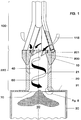
- Fig. 1 shows the overall structure of a burner operated as a premix burner becomes.
- a swirl generator 100 is effective, the design of which is shown in FIGS the following Fig. 3-6 is shown and described in more detail. It is about in this swirl generator 100 around a conical structure, the tangential multiple is acted upon by an inflowing combustion air flow 115.
- the flow formed here is based on a downstream of the swirl generator 100 provided transition geometry seamlessly into a transition piece 200 transferred in such a way that no detachment areas can occur there.
- the Configuration of this transition geometry is described in more detail in FIG. 6.
- This transition piece 200 is on the outflow side of the transition geometry extended by a mixing tube 20, both parts of the actual mixing section Form 220.
- the mixing section 220 can be made from a single one Consist of pieces, i.e. then that the transition piece 200 and the mixing tube 20 merge into a single coherent structure, but the Characteristics of each part are retained.
- transition piece 200 and mixing tube 20 created from two parts these are through a sleeve ring 10 connected, the same socket ring 10 on the head side as an anchoring surface serves for the swirl generator 100.
- Such a sleeve ring 10 also has the advantage that different mixing tubes can be used.
- Outflow side of the mixing tube 20 there is the actual combustion chamber 30 Combustion chamber, which is only symbolized here by a flame tube.
- the Mixing section 220 largely fulfills the task that is downstream of the swirl generator 100 a defined route is provided, in which a perfect premix of different types of fuel can be achieved.
- This mixing section so primarily the mixing tube 20, also allows lossless Flow guidance, so that it is also in operative connection with the transition geometry initially cannot form a backflow zone or backflow bubble, with which over the length of the mixing section 220 to the mixing quality for all types of fuel Influence can be exercised.
- this mixing section 220 still has one other property, which is that in it the axial velocity profile has a pronounced maximum on the axis, so that backfire the flame from the combustion chamber is not possible. However, it is correct that with such a configuration this axial velocity towards the wall falls off.
- the mixing tube 20 in the flow and circumferential direction with a number of regular or irregular distributed holes 21 of various cross sections and directions through which an amount of air flows into the interior of the mixing tube 20, and along the wall in the sense of a filming an increase in the flow rate induce.
- These holes 21 can also be designed that at least additionally on the inner wall of the mixing tube 20 stops effusion cooling.
- these bores 21 are also possible. It is also possible for the mixing tube 20 to be intermittent to provide such holes, for example at the beginning and end of the same. These bores 21 are preferably distributed around the circumference of the mixing tube. Furthermore, the outlet of the transition channels 201 corresponds to the narrowest Flow cross-section of the mixing tube 20. The above-mentioned transition channels 201 thus bridge the respective cross-sectional difference without the to negatively influence formed flow. If the chosen precaution at the guidance of the pipe flow 40 along the mixing pipe 20 an intolerable If pressure loss triggers, this can be remedied by At the end of this mixing tube 20, a diffuser, not shown in the figure, is provided becomes.
- a combustion chamber then closes at the end of the mixing tube 20 30 (combustion chamber), with a through between the two flow cross-sections there is a cross-sectional jump formed in the burner front. Only here does it form a central flame front with a backflow zone 50, which is opposite the Flame front has the properties of a disembodied flame holder. Forms there is a flow within this cross-sectional jump during operation Edge zone, in which by the prevailing negative pressure Vortex detachments occur, this leads to an increased ring stabilization of the Backflow zone 50. It should also be mentioned that the generation of a stable backflow zone 50 also a sufficiently high swirl number in one Tube required.
- FIG. 2 shows a schematic view of the burner according to FIG. 1, in particular here on the washing around a centrally arranged fuel nozzle 103 and the effect of fuel injectors 170 is pointed out.
- the mode of action the remaining main components of the burner, namely swirl generator 100 and Transition piece 200 are described in more detail in the following figures.
- the fuel nozzle 103 is encased with a spaced ring 190, in which has a number of holes 161 arranged in the circumferential direction, through which an amount of air 160 flows into an annular chamber 180 and there rinsing the fuel nozzle 103. These holes 161 are slanted forward so that an adequate axial component arises on the burner axis 60.
- additional fuel injectors 170 are provided, which have a specific one Amount of preferably a gaseous fuel in the respective amount of air Feed 160 such that there is a uniform fuel concentration in the mixing tube 20 150 sets over the flow cross section, as the illustration wants to symbolize in the figure.
- Exactly this even fuel concentration 150, especially the strong concentration on the burner axis 60 provides that there is a stabilization of the flame front at the exit of the burner sets, thus avoiding occurring combustion chamber pulsations.
- FIG. 4 is used at the same time as FIG. 3.
- 3 is referred to the other figures as necessary in the description of FIG.
- the first part of the burner according to FIG. 1 forms the swirl generator shown in FIG. 3 100.
- This consists of two high conical partial bodies 101, 102, which are nested in a staggered manner.
- the number of conical Partial body can of course be larger than two, like Figures 5 and 6 demonstrate; this depends on how they are explained in more detail below depends on the operating mode of the entire burner. It is with certain operating constellations not ruled out a single spiral Provide swirl generator.
- the offset of the respective central axis or Longitudinal symmetry axes 101b, 102b (see FIG. 4) of the tapered partial bodies 101, 102 creates each other in the neighboring wall, in a mirror image arrangement, each have a tangential inflow channel, i.e.
- the cone shape of the Part body 101, 102 shown in the flow direction has a certain fixed Angle on.
- the partial bodies 101, 102 have an increasing or decreasing cone inclination in the direction of flow, similar to a trumpet or Tulip. The latter two forms are not included in the drawing, since they can be easily understood by a person skilled in the art are.
- the two conical partial bodies 101, 102 each have a cylindrical one annular starting part 101a. In the area of this cylindrical initial part the fuel nozzle 103 already mentioned under FIG.
- the injection 104 of this fuel 112 falls approximately with the narrowest cross section of the formed by the conical part body 101, 102 cone cavity 114 together.
- the injection capacity and the type of this fuel nozzle 103 are determined according to the given parameters of the respective burner.
- the tapered body 101, 102 also each have a fuel line 108, 109, which arranged along the tangential air inlet slots 119, 120 and with injection openings 117 are provided, through which preferably a gaseous Fuel 113 is injected into the combustion air 115 flowing through there, as the arrows 116 symbolize.
- fuel lines 108, 109 are preferably at the latest at the end of the tangential inflow, before entering the cone cavity 114, arranged for an optimal air / fuel mixture to obtain.
- fuel 112 is normally a liquid Fuel, forming a mixture with another medium, for example with a recirculated flue gas, is easily possible. That fuel 112 is into the cone cavity 114 at a preferably very acute angle injected. A conical fuel spray thus forms from the fuel nozzle 103 105, the rotating combustion air flowing in tangentially 115 enclosed and dismantled.
- the concentration is then in the axial direction of the injected fuel 112 continuously through the inflowing combustion air 115 degraded to mix in the direction of evaporation.
- a gaseous fuel 113 is introduced via the opening nozzles 117 the formation of the fuel / air mixture directly at the end of the air inlet slots 119, 120.
- the combustion air 115 additionally preheated, or for example enriched with a recirculated flue gas or exhaust gas, so supported this sustained the vaporization of the liquid fuel 112 before this mixture flows into the downstream stage, here into the transition piece 200 (See Figures 1 and 7).
- the same considerations also apply when talking about the Lines 108, 109 liquid fuels should be supplied.
- the tangential air inlet slots 119, 120 are strictly limited, so that the desired flow field of the combustion air 115 at the exit of the swirl generator 100 can adjust.
- one Reduction of the tangential air inlet slots 119, 120 the faster formation a backflow zone already favored in the area of the swirl generator.
- the axial speed within the swirl generator 100 can be by a corresponding increase supply of air as described in Fig. 2 (Item 160) or stabilize.
- a corresponding swirl generation in operative connection with the downstream transition piece 200 prevents formation of flow separation within the swirl generator 100 downstream Mixing tube.
- the construction of the swirl generator 100 is suitable further excellent, the size of the tangential air inlet slots 119, 120 to change, with which without changing the overall length of the swirl generator 100 relatively large operational bandwidth can be captured.
- the partial bodies 101, 102 can also be displaced relative to one another in another plane, as a result of which even an overlap of the same can be provided. It is the further possible, the partial body 101, 102 by a counter-rotating movement to nest in a spiral.
- FIG. 4 shows, among other things, the geometric configuration of optional ones Baffles 121a, 121b. They have a flow initiation function these, according to their length, the respective end of the tapered partial body 101, 102 extend in the direction of flow towards the combustion air 115.
- the channeling of the combustion air 115 into the cone cavity 114 can by opening or closing the guide plates 121a, 121b by one in the area the point of entry of this channel into the cone cavity 114 123 can be optimized, especially if the original Gap size of the tangential air inlet slots 119, 120 changed dynamically should be, for example, to change the speed of the combustion air 115 to achieve.
- these can be dynamic arrangements can also be provided statically, by using required baffles form an integral part with the tapered partial bodies 101, 102.
- the swirl generator 100 now consists of four partial bodies 130, 131, 132, 133 is constructed.
- the associated longitudinal symmetry axes for each sub-body are marked with the letter a.
- this configuration is to be said that they are due to the lower generated with it Twist strength and in cooperation with a correspondingly enlarged slot width best suited, the bursting of the vortex flow on the downstream side of the To prevent swirl generator in the mixing tube, with which the mixing tube the intended Role.
- FIG. 6 differs from FIG. 5 in that the partial bodies 140 here 141, 142, 143 have a blade profile shape which is used to provide a certain Flow is provided. Otherwise, the mode of operation of the swirl generator stayed the same.
- the admixture of fuel 116 in the combustion air flow 115 happens from inside the blade profiles, i.e. the fuel line 108 is now integrated in the individual blades.
- the transition geometry is corresponding for a swirl generator 100 with four partial bodies 5 or 6, built. Accordingly, the transition geometry points as Natural extension of the upstream part of the four transition channels 201, whereby the conical quarter area of the partial bodies is extended, until it cuts the wall of the mixing tube.
- the same considerations apply even if the swirl generator is based on a principle other than that described under FIG. 3, is constructed.
- the downward flow area of the individual transition channels 201 has a spiral shape in the flow direction running shape, which describes a crescent shape, accordingly the fact that in the present case the flow cross-section of the transition piece 200 flared in the direction of flow.
- the twist angle of the Transition channels 201 in the flow direction are selected so that the pipe flow then another one until the cross-sectional jump at the combustion chamber inlet enough distance remains to allow a perfect premix with the injected To accomplish fuel. It also increases by the above Measures include the axial speed on the mixing tube wall downstream of the swirl generator. The transition geometry and the measures in the area of the mixing tube cause a significant increase in the axial speed profile towards the center of the mixing tube, so there is a risk of early ignition is decisively counteracted.
- FIG. 8 shows the geometric design of the burner outlet at the end of the mixing tube 20 already mentioned for spatial stabilization of the backflow zone.
- the flow cross-section of the tube 20 receives in this area a first transition radius R 1 which is convex with respect to the burner axis 60, the size of which basically depends on the respective flow within the mixing tube 20.
- the size of this radius R 1 is accordingly chosen so that the flow is applied to the wall and the swirl number can increase sharply.
- the size of the radius R 1 can be quantitatively defined so that it is> 10% of the inner diameter d of the mixing tube 20. Compared to a flow without a radius, the backflow zone 50 now increases enormously.
- This radius R 1 then merges into a second radius R 2 , which is concave with respect to the burner axis 60 up to the exit plane 70 of the mixing tube 20, the size of this radius R 2 being > 10% of the inside diameter d of the mixing tube 20.
- This second radius R 2 ensures that the edge flow is aligned axially in such a way that the flame does not appear on the combustion chamber wall when the combustion chamber is of small radial dimension.
- the sectoral angles ⁇ 1 and ⁇ 2 of the two radii R 1 , R 2 are complementary angles, the maximum sum of which is 90 °. Depending on the number of swirls and the axial orientation of the flow, the two angles mentioned are appropriately adapted, which is interdependent on the size of the two radii.
- the exit plane 70 of the mixing tube 20 is further provided from the end edge of the second radius R 2 in the radial direction with a step S of> 3 mm depth, this step performing the function of a stall stage.
Landscapes
- Engineering & Computer Science (AREA)
- Chemical & Material Sciences (AREA)
- Combustion & Propulsion (AREA)
- Mechanical Engineering (AREA)
- General Engineering & Computer Science (AREA)
- Gas Burners (AREA)
- Sorption Type Refrigeration Machines (AREA)
- Combustion Of Fluid Fuel (AREA)
Priority Applications (4)
| Application Number | Priority Date | Filing Date | Title |
|---|---|---|---|
| DE59709281T DE59709281D1 (de) | 1997-11-25 | 1997-11-25 | Brenner zum Betrieb eines Wärmeerzeugers |
| EP97810907A EP0919768B1 (fr) | 1997-11-25 | 1997-11-25 | Brûleur pour la mise en oeuvre d'un générateur de chaleur |
| AT97810907T ATE232282T1 (de) | 1997-11-25 | 1997-11-25 | Brenner zum betrieb eines wärmeerzeugers |
| US09/196,115 US5954490A (en) | 1997-11-25 | 1998-11-20 | Burner for operating a heat generator |
Applications Claiming Priority (1)
| Application Number | Priority Date | Filing Date | Title |
|---|---|---|---|
| EP97810907A EP0919768B1 (fr) | 1997-11-25 | 1997-11-25 | Brûleur pour la mise en oeuvre d'un générateur de chaleur |
Publications (2)
| Publication Number | Publication Date |
|---|---|
| EP0919768A1 true EP0919768A1 (fr) | 1999-06-02 |
| EP0919768B1 EP0919768B1 (fr) | 2003-02-05 |
Family
ID=8230493
Family Applications (1)
| Application Number | Title | Priority Date | Filing Date |
|---|---|---|---|
| EP97810907A Expired - Lifetime EP0919768B1 (fr) | 1997-11-25 | 1997-11-25 | Brûleur pour la mise en oeuvre d'un générateur de chaleur |
Country Status (4)
| Country | Link |
|---|---|
| US (1) | US5954490A (fr) |
| EP (1) | EP0919768B1 (fr) |
| AT (1) | ATE232282T1 (fr) |
| DE (1) | DE59709281D1 (fr) |
Cited By (2)
| Publication number | Priority date | Publication date | Assignee | Title |
|---|---|---|---|---|
| DE10026122A1 (de) * | 2000-05-26 | 2001-11-29 | Abb Alstom Power Nv | Brenner für einen Wärmeerzeuger |
| DE10056243A1 (de) * | 2000-11-14 | 2002-05-23 | Alstom Switzerland Ltd | Brennkammer und Verfahren zum Betrieb dieser Brennkammer |
Families Citing this family (8)
| Publication number | Priority date | Publication date | Assignee | Title |
|---|---|---|---|---|
| DE19859829A1 (de) * | 1998-12-23 | 2000-06-29 | Abb Alstom Power Ch Ag | Brenner zum Betrieb eines Wärmeerzeugers |
| DE59907942D1 (de) * | 1999-07-22 | 2004-01-15 | Alstom Switzerland Ltd | Vormischbrenner |
| DE10064259B4 (de) * | 2000-12-22 | 2012-02-02 | Alstom Technology Ltd. | Brenner mit hoher Flammenstabilität |
| EP1262714A1 (fr) * | 2001-06-01 | 2002-12-04 | ALSTOM (Switzerland) Ltd | Brûleur avec recirculation des gaz de combustion |
| US6889523B2 (en) * | 2003-03-07 | 2005-05-10 | Elkcorp | LNG production in cryogenic natural gas processing plants |
| EP1817526B1 (fr) * | 2004-11-30 | 2019-03-20 | Ansaldo Energia Switzerland AG | Procédé et dispositif de combustion d'hydrogène dans un brûleur a prémelange |
| EP1843098A1 (fr) * | 2006-04-07 | 2007-10-10 | Siemens Aktiengesellschaft | Chambre de combustion pour turbine à gaz |
| CH701905A1 (de) * | 2009-09-17 | 2011-03-31 | Alstom Technology Ltd | Verfahren zum Verbrennen wasserstoffreicher, gasförmiger Brennstoffe in einem Brenner sowie Brenner zur Durchführung des Verfahrens. |
Citations (4)
| Publication number | Priority date | Publication date | Assignee | Title |
|---|---|---|---|---|
| EP0321809B1 (fr) | 1987-12-21 | 1991-05-15 | BBC Brown Boveri AG | Procédé pour la combustion de combustible liquide dans un brûleur |
| EP0430376A2 (fr) * | 1989-12-01 | 1991-06-05 | International Flame Research Foundation | Procédé de combustion pour combustible avec alimentation étagée du combustible et brûleur à cet effet |
| EP0644374A2 (fr) * | 1993-09-15 | 1995-03-22 | The Boc Group, Inc. | Brûleur oxy-combustible et procédé d'utilisation |
| EP0780629A2 (fr) | 1995-12-21 | 1997-06-25 | ABB Research Ltd. | Brûleur pour un générateur de chaleur |
Family Cites Families (3)
| Publication number | Priority date | Publication date | Assignee | Title |
|---|---|---|---|---|
| US2762428A (en) * | 1953-02-05 | 1956-09-11 | Selas Corp Of America | Gas-fueled radiant burner |
| US3083759A (en) * | 1957-08-13 | 1963-04-02 | Selas Corp Of America | Radiant cup gas burner |
| US4416620A (en) * | 1981-06-08 | 1983-11-22 | Selas Corporation Of America | Larger capacity Vortex burner |
-
1997
- 1997-11-25 AT AT97810907T patent/ATE232282T1/de not_active IP Right Cessation
- 1997-11-25 DE DE59709281T patent/DE59709281D1/de not_active Expired - Lifetime
- 1997-11-25 EP EP97810907A patent/EP0919768B1/fr not_active Expired - Lifetime
-
1998
- 1998-11-20 US US09/196,115 patent/US5954490A/en not_active Expired - Fee Related
Patent Citations (4)
| Publication number | Priority date | Publication date | Assignee | Title |
|---|---|---|---|---|
| EP0321809B1 (fr) | 1987-12-21 | 1991-05-15 | BBC Brown Boveri AG | Procédé pour la combustion de combustible liquide dans un brûleur |
| EP0430376A2 (fr) * | 1989-12-01 | 1991-06-05 | International Flame Research Foundation | Procédé de combustion pour combustible avec alimentation étagée du combustible et brûleur à cet effet |
| EP0644374A2 (fr) * | 1993-09-15 | 1995-03-22 | The Boc Group, Inc. | Brûleur oxy-combustible et procédé d'utilisation |
| EP0780629A2 (fr) | 1995-12-21 | 1997-06-25 | ABB Research Ltd. | Brûleur pour un générateur de chaleur |
Cited By (3)
| Publication number | Priority date | Publication date | Assignee | Title |
|---|---|---|---|---|
| DE10026122A1 (de) * | 2000-05-26 | 2001-11-29 | Abb Alstom Power Nv | Brenner für einen Wärmeerzeuger |
| DE10056243A1 (de) * | 2000-11-14 | 2002-05-23 | Alstom Switzerland Ltd | Brennkammer und Verfahren zum Betrieb dieser Brennkammer |
| US6688111B2 (en) | 2000-11-14 | 2004-02-10 | Alstom Technology Ltd | Method for operating a combustion chamber |
Also Published As
| Publication number | Publication date |
|---|---|
| DE59709281D1 (de) | 2003-03-13 |
| ATE232282T1 (de) | 2003-02-15 |
| EP0919768B1 (fr) | 2003-02-05 |
| US5954490A (en) | 1999-09-21 |
Similar Documents
| Publication | Publication Date | Title |
|---|---|---|
| EP0780629B1 (fr) | Brûleur pour un générateur de chaleur | |
| EP0704657B1 (fr) | Brûleur | |
| EP0780630B1 (fr) | Brûleur pour un générateur de chaleur | |
| EP0918191B1 (fr) | Brûleur pour la mise en oeuvre d'un générateur de chaleur | |
| EP0918190A1 (fr) | Brûleur pour la mise en oeuvre d'un générateur de chaleur | |
| EP0899508B1 (fr) | Brûleur pour un dispositif à chaleur | |
| EP0833105B1 (fr) | Brûleur à prémélange | |
| DE19757189B4 (de) | Verfahren zum Betrieb eines Brenners eines Wärmeerzeugers | |
| EP0797051B1 (fr) | Brûleur pour un générateur de chaleur | |
| EP0777081B1 (fr) | Brûleur à prémélange | |
| EP0321809A1 (fr) | Procédé pour la combustion de combustible liquide dans un brûleur | |
| EP0994300B1 (fr) | Brûleur pour la conduite d'un générateur de chaleur | |
| EP0775869B1 (fr) | Brûleur à prémélange | |
| EP0916894B1 (fr) | Brûleur pour la mise en oeuvre d'un générateur de chaleur | |
| EP0931980B1 (fr) | Brûleur pour la mise en oeuvre d'un générateur de chaleur | |
| EP0987493B1 (fr) | Brûleur pour générateur de chaleur | |
| EP0909921B1 (fr) | Brûleur pour la mise en oeuvre d'un générateur de chaleur | |
| EP0919768B1 (fr) | Brûleur pour la mise en oeuvre d'un générateur de chaleur | |
| EP0903540B1 (fr) | Brûleur pour la mise en oeuvre d'un générateur de chaleur | |
| EP0833104B1 (fr) | Brûleur pour le fonctionnement d'une chambre de combustion | |
| EP0913630B1 (fr) | Brûleur pour la mise en oeuvre d'un générateur de chaleur | |
| DE19537636B4 (de) | Kraftwerksanlage | |
| DE19914666B4 (de) | Brenner für einen Wärmeerzeuger | |
| EP0899506A2 (fr) | Dispositif de combustion | |
| EP0780628B1 (fr) | Brûleur à prémélange pour un générateur de chaleur |
Legal Events
| Date | Code | Title | Description |
|---|---|---|---|
| PUAI | Public reference made under article 153(3) epc to a published international application that has entered the european phase |
Free format text: ORIGINAL CODE: 0009012 |
|
| AK | Designated contracting states |
Kind code of ref document: A1 Designated state(s): AT CH DE FR GB LI |
|
| AX | Request for extension of the european patent |
Free format text: AL;LT;LV;MK;RO;SI |
|
| 17P | Request for examination filed |
Effective date: 19991104 |
|
| AKX | Designation fees paid |
Free format text: AT CH DE FR GB LI SE |
|
| RBV | Designated contracting states (corrected) |
Designated state(s): AT CH DE FR GB LI |
|
| GRAG | Despatch of communication of intention to grant |
Free format text: ORIGINAL CODE: EPIDOS AGRA |
|
| 17Q | First examination report despatched |
Effective date: 20020508 |
|
| GRAG | Despatch of communication of intention to grant |
Free format text: ORIGINAL CODE: EPIDOS AGRA |
|
| GRAH | Despatch of communication of intention to grant a patent |
Free format text: ORIGINAL CODE: EPIDOS IGRA |
|
| RAP1 | Party data changed (applicant data changed or rights of an application transferred) |
Owner name: ALSTOM |
|
| GRAH | Despatch of communication of intention to grant a patent |
Free format text: ORIGINAL CODE: EPIDOS IGRA |
|
| GRAA | (expected) grant |
Free format text: ORIGINAL CODE: 0009210 |
|
| AK | Designated contracting states |
Designated state(s): AT CH DE FR GB LI |
|
| REG | Reference to a national code |
Ref country code: GB Ref legal event code: FG4D Free format text: NOT ENGLISH |
|
| REG | Reference to a national code |
Ref country code: CH Ref legal event code: EP |
|
| REF | Corresponds to: |
Ref document number: 59709281 Country of ref document: DE Date of ref document: 20030313 Kind code of ref document: P |
|
| GBT | Gb: translation of ep patent filed (gb section 77(6)(a)/1977) | ||
| ET | Fr: translation filed | ||
| PG25 | Lapsed in a contracting state [announced via postgrant information from national office to epo] |
Ref country code: AT Free format text: LAPSE BECAUSE OF NON-PAYMENT OF DUE FEES Effective date: 20031125 |
|
| PG25 | Lapsed in a contracting state [announced via postgrant information from national office to epo] |
Ref country code: LI Free format text: LAPSE BECAUSE OF NON-PAYMENT OF DUE FEES Effective date: 20031130 Ref country code: CH Free format text: LAPSE BECAUSE OF NON-PAYMENT OF DUE FEES Effective date: 20031130 |
|
| PLBE | No opposition filed within time limit |
Free format text: ORIGINAL CODE: 0009261 |
|
| STAA | Information on the status of an ep patent application or granted ep patent |
Free format text: STATUS: NO OPPOSITION FILED WITHIN TIME LIMIT |
|
| 26N | No opposition filed |
Effective date: 20031106 |
|
| REG | Reference to a national code |
Ref country code: CH Ref legal event code: PL |
|
| REG | Reference to a national code |
Ref country code: DE Ref legal event code: R409 Ref document number: 59709281 Country of ref document: DE |
|
| REG | Reference to a national code |
Ref country code: DE Ref legal event code: R119 Ref document number: 59709281 Country of ref document: DE Effective date: 20110531 |
|
| PG25 | Lapsed in a contracting state [announced via postgrant information from national office to epo] |
Ref country code: DE Free format text: LAPSE BECAUSE OF NON-PAYMENT OF DUE FEES Effective date: 20110531 |
|
| REG | Reference to a national code |
Ref country code: DE Ref legal event code: R409 Ref document number: 59709281 Country of ref document: DE Ref country code: DE Ref legal event code: R074 Ref document number: 59709281 Country of ref document: DE |
|
| PGRI | Patent reinstated in contracting state [announced from national office to epo] |
Ref country code: DE Effective date: 20111109 |
|
| REG | Reference to a national code |
Ref country code: FR Ref legal event code: PLFP Year of fee payment: 19 |
|
| REG | Reference to a national code |
Ref country code: FR Ref legal event code: PLFP Year of fee payment: 20 |
|
| PGFP | Annual fee paid to national office [announced via postgrant information from national office to epo] |
Ref country code: GB Payment date: 20161114 Year of fee payment: 20 Ref country code: FR Payment date: 20161123 Year of fee payment: 20 |
|
| PGFP | Annual fee paid to national office [announced via postgrant information from national office to epo] |
Ref country code: DE Payment date: 20170120 Year of fee payment: 20 |
|
| REG | Reference to a national code |
Ref country code: DE Ref legal event code: R071 Ref document number: 59709281 Country of ref document: DE |
|
| REG | Reference to a national code |
Ref country code: GB Ref legal event code: PE20 Expiry date: 20171124 |
|
| PG25 | Lapsed in a contracting state [announced via postgrant information from national office to epo] |
Ref country code: GB Free format text: LAPSE BECAUSE OF EXPIRATION OF PROTECTION Effective date: 20171124 |